
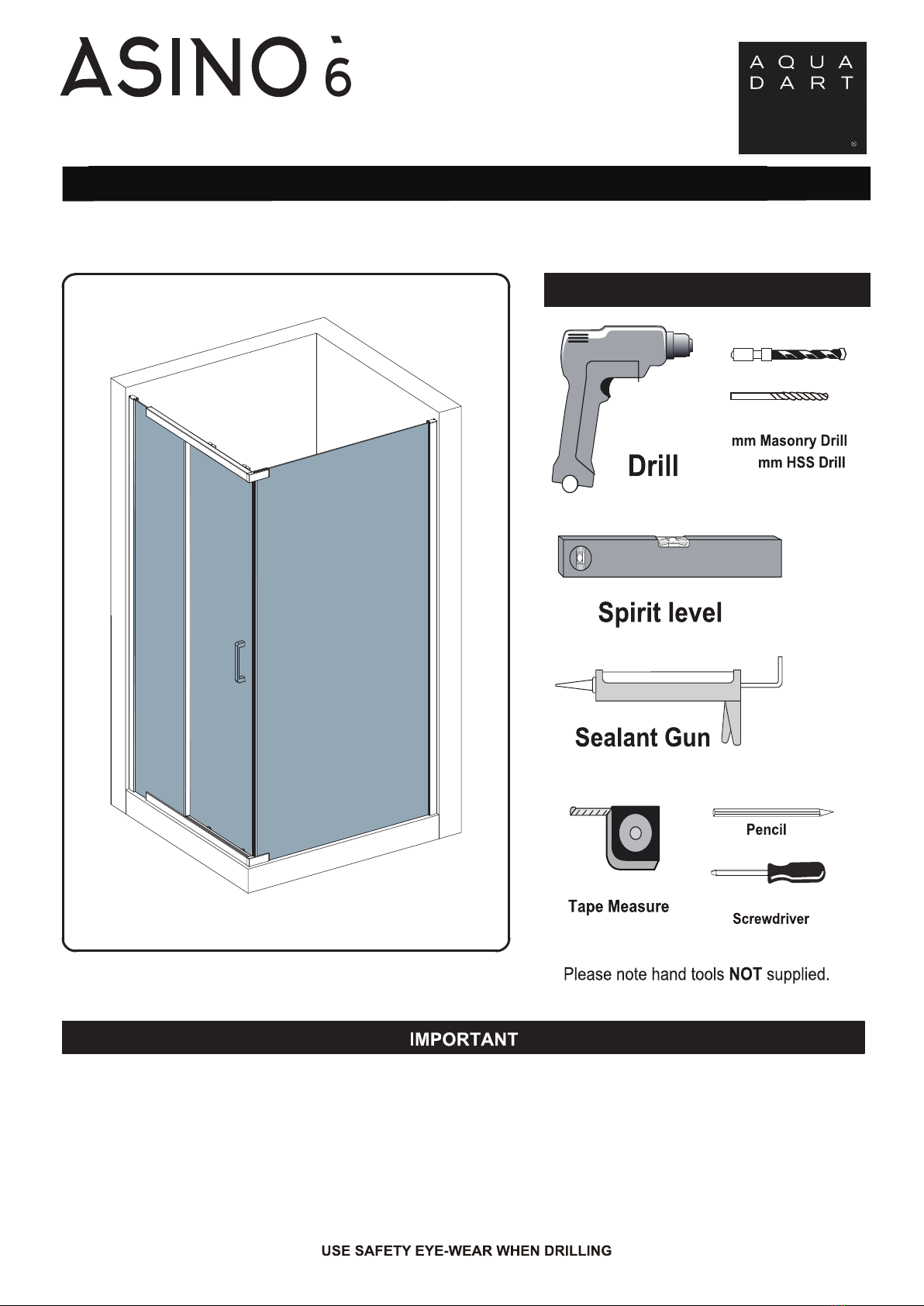
INSTALLATION INSTRUCTIONS
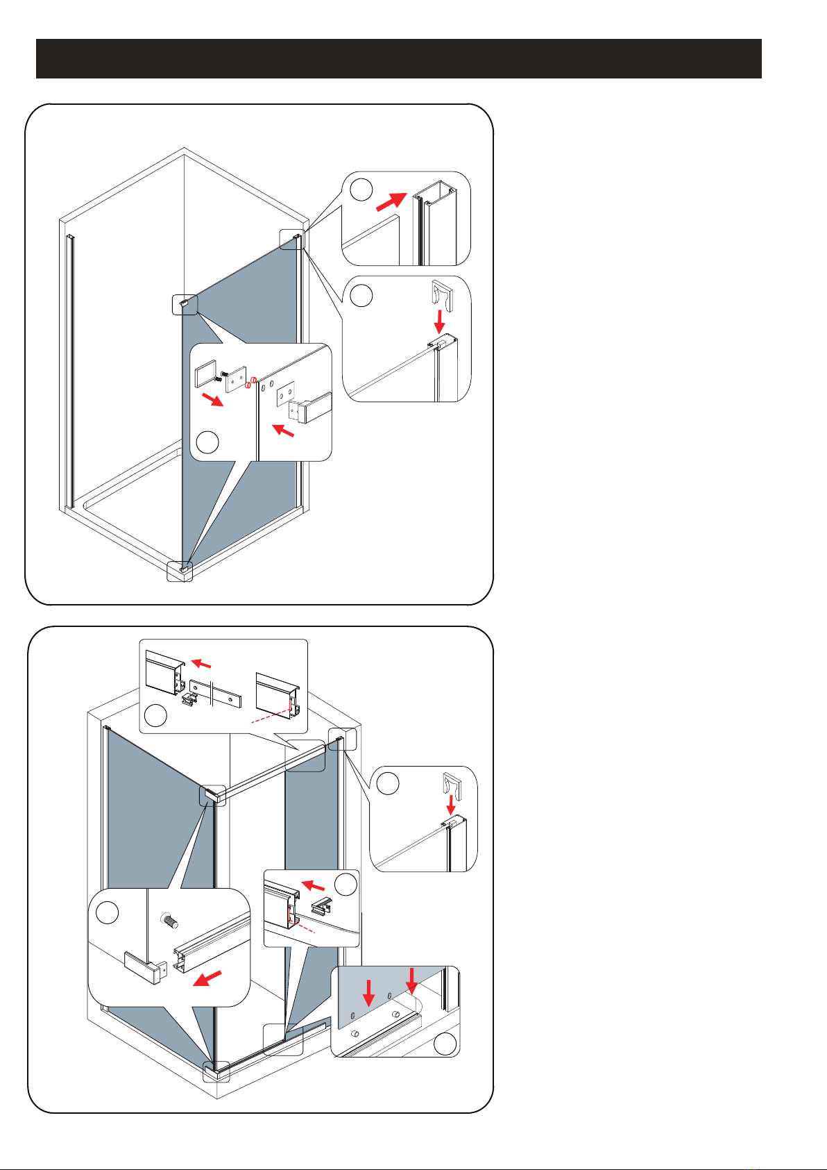
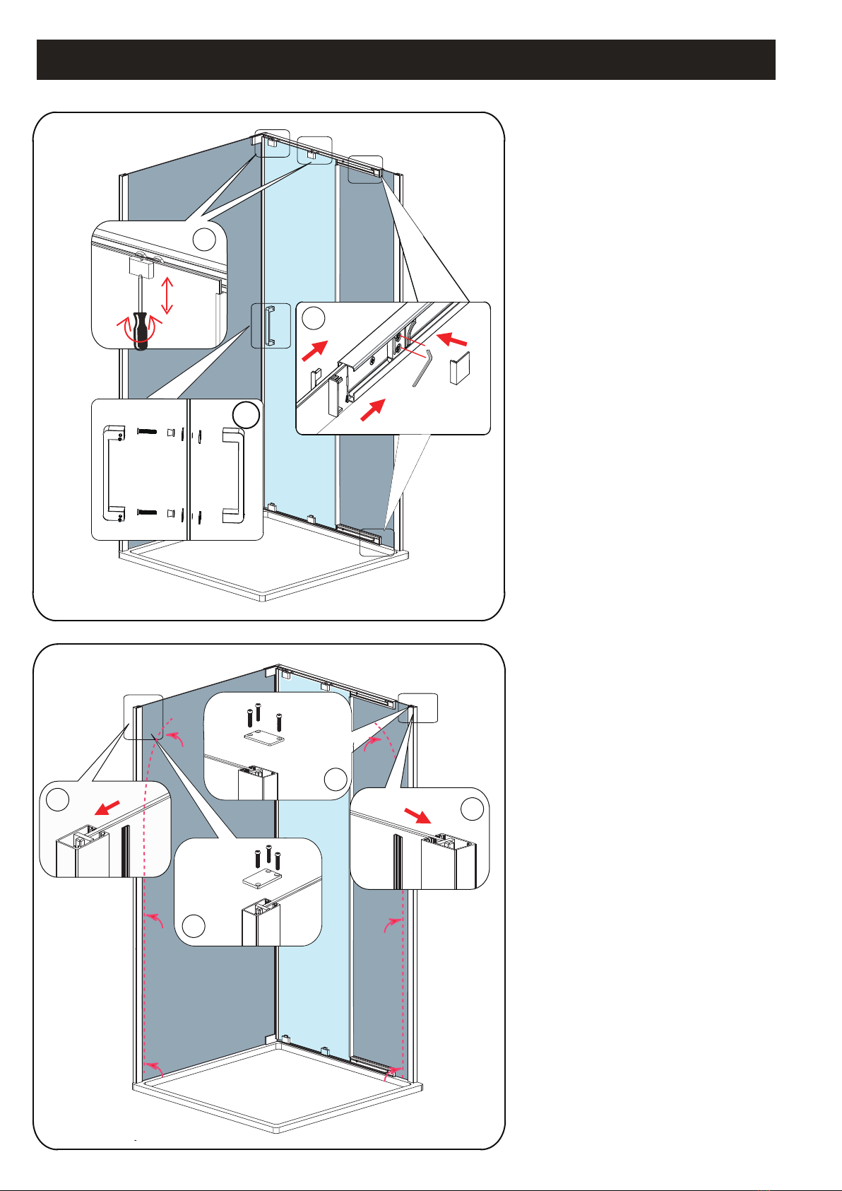
Step 2.1 Insert the side panel glass( no.28)
into the wall profile(no.24).(Dagram B)
Step 2.2
Then fit the glass blocker (no.27)
onto the groove at the top of the
side panel glass.(Diagram C)
Step 2.3 Insert the washers (no.29) into the
holes on the side panel glass. Fix the
rail fixing (no.30) onto top and bottom
of the side panel glass using screws
M6x14. Ensure the gasket has placed
both inside and outside of the glass.
panel. (Diagram D).
Step 3.1 Fit the correct hand of the glass edge
(no.11) onto the bottom rail.Ensure the
glass fixing strip is inserted into the rail
and it’s flush with the rail end.(Diagram E).
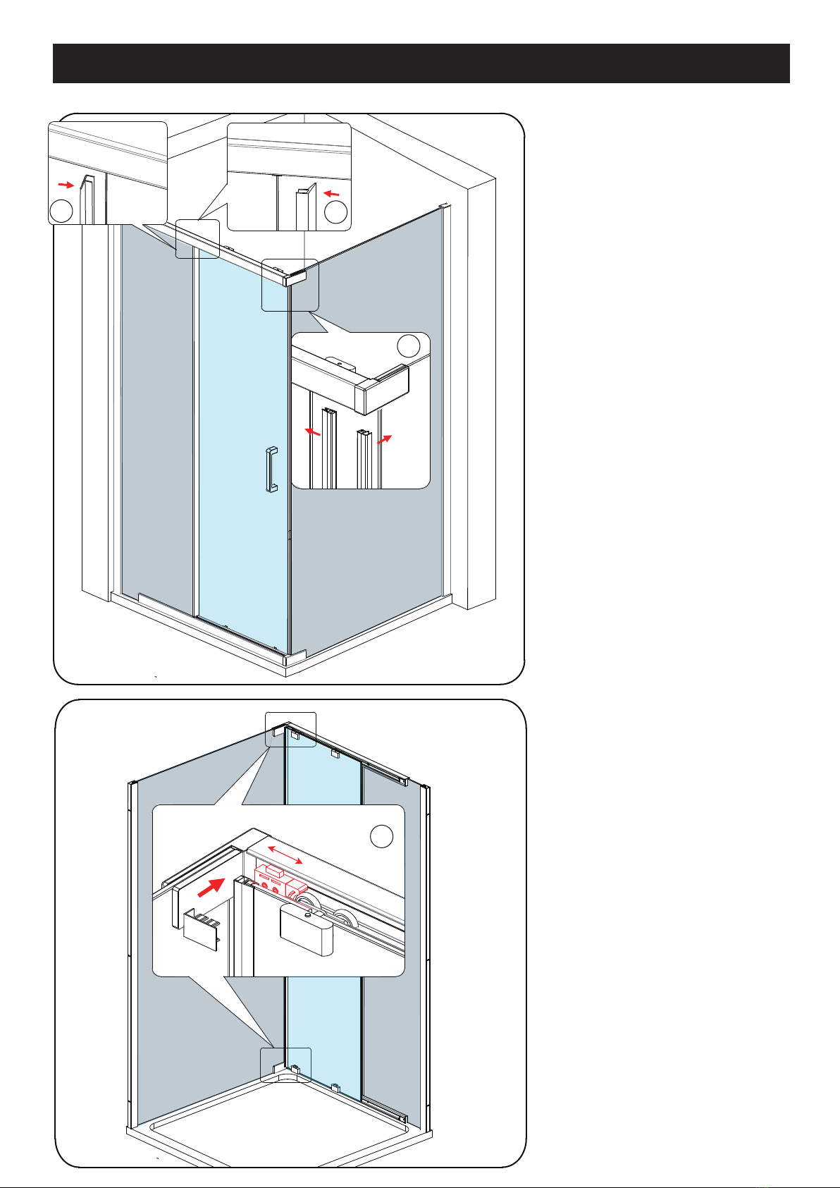
Insert the bottom rail onto the rail fixing
fixed at the bottom of the side panel.
Secure the parts together using the
screw M4x10 through the pre-drilled hole
on the rail.(Diagram F).
Step 3.3 Fit the washers (no.29) into the holes on
the fixed panel (no.4) then insert the
fixed panel into the bottom rail and wall
profile.(Diagram G).
Step 3.4 Fit the glass blocker (no.9) in
to the
groove at the top of the fixed panel.
(Diagram H).
Step 3.5 Fit the other glass edge cover (no.11)
onto the top rail. Ensure the glass
fixing strip has been inserted into the
rail and it’s flush with the rail end.
(Diagram I).
Step 3.6 Insert the top rail onto the rail fixing fixed
at the top of the side panel using screw
M4x10 to fix the parts together through
the pre-drilled hole on the rail.
(Diagram F).
Flush
B
C
E
D
M6x14
F
Step 3.2
G
H
Flush
I


 user manual")


