Arctic Heat Pumps V4 Service manual

1
INSTALLATION & INSTRUCTION
MANUAL
EVI DC INVERTER
AIR TO WATER HEAT PUMP
V4
Aug 2022

2
2
Contents
Notice –Warnings..............................................................................................................................................................4
Specification.......................................................................................................................................................................5
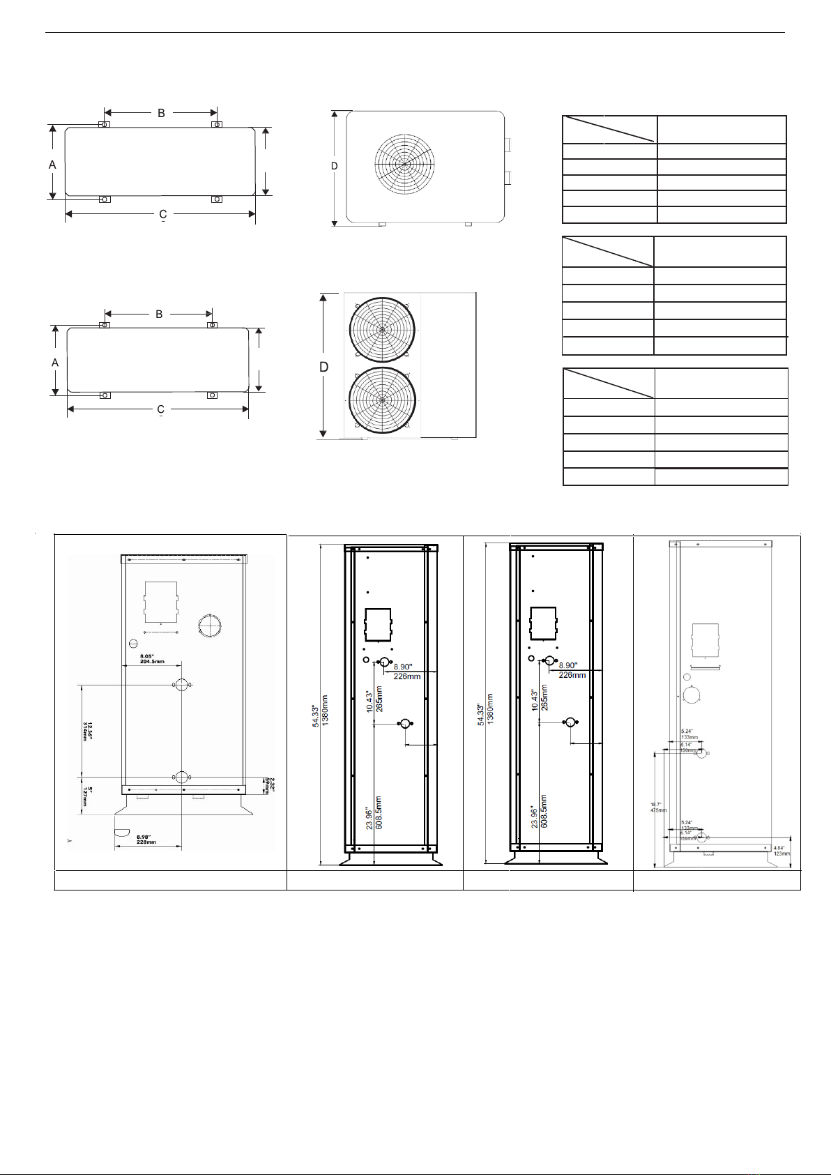
Technical Parameters of Arctic Air to Water Heat Pumps..........................................................................................5
Heating Performance Table............................................................................................................................................6
Recommended Circulation Pump (External) ..................................................................................................................8
Heat Pump Flow Pressure Drop Curves..........................................................................................................................8
Installation........................................................................................................................................................................10
Heat Pump Installation ...............................................................................................................................................10
Accessing Additional Heat Pump Parts.....................................................................................................................12
Installation Space Requirements:.................................................................................................................................13
Buffer Tank Installation...............................................................................................................................................13
Installation of Indoor Heating and Cooling Equipment ..............................................................................................14
Water Pipe Connections..............................................................................................................................................14
Installation of the Temperature Sensor.......................................................................................................................15
Electrical Wiring...........................................................................................................................................................15
Electrical Wire Selection –Warning............................................................................................................................16
What Gets Connected and Where................................................................................................................................16
Start Up.........................................................................................................................................................................19
Single Tank versus Dual Tank...........................................................................................................................................20
The Use of the Wired Controller ..................................................................................................................................21
Buttons and Display Symbols Explanation....................................................................................................................21
Wired Controller Operations .......................................................................................................................................22
Keyboard Locking / Unlocking Operation.................................................................................................................22
Turning the Unit ON/OFF..........................................................................................................................................22
Modifying the Temperature Setting ........................................................................................................................22
Mode Select Operation............................................................................................................................................22
Forced Defrost ..........................................................................................................................................................24
Clock Setting .............................................................................................................................................................24
Changing Between Celsius & Fahrenheit
...............................................................................................................24
Factory Reset
...........................................................................................................................................................24
Timer ON/OFF Settings...........................................................................................................................................24
Cancelling Timer Operation
....................................................................................................................................24
Timer Programming..................................................................................................................................................25
Selecting Energy Saving Mode, Quiet Running Mode, and Fast Heating Mode.......................................................26
Checking of State Parameters .............................................................................................................................26
MaintenanceandRepair................................................................................................................................................27
Antifreeze Protection for Cold Climates .....................................................................................................................27
Error Code Table
............................................................................................................................................................28
Wiring Diagrams...............................................................................................................................................................30

3
3
Controller Board ...........................................................................................................................................................30
Wiring Diagram Single Tank - Basic...............................................................................................................................32
Wiring Diagram Single Tank –HBX ...............................................................................................................................33
Overview..............................................................................................................................................................33
Wiring Diagram Dual Tank –Basic................................................................................................................................35
Wiring Diagram Dual Tank –HBX..................................................................................................................................36
Intelligent Defrost............................................................................................................................................................37
Enter Defrost Mode..................................................................................................................................................37
Exit Defrost Mode.....................................................................................................................................................37
Back Up Heating...............................................................................................................................................................37
Turn On.....................................................................................................................................................................37
Turn Off.....................................................................................................................................................................37
Back Up Heater.............................................................................................................................................................38
AltSource Integration....................................................................................................................................................38
External Boiler Integration............................................................................................................................................39
HBX Advanced Back Up ECO-0600................................................................................................................................41
Domestic Hot Water ........................................................................................................................................................43
3-Way Valves....................................................................................................................................................................45
Multiple Heat Pumps .......................................................................................................................................................46
Wiring Cn31 in series for Dual Heat Pumps..............................................................................................................48
..................................................................................................................................................................................48
Heating and Cooling - BASIC ............................................................................................................................................49
Heating and Cooling –Advanced.....................................................................................................................................50
ECO-0600 Heating Cooling Reset..................................................................................................................................51
WARRANTY.......................................................................................................................................................................53

4
4
Notice –Warnings
To use this product better and more safely, please read this manual carefully before
installation
and initial operation.
Save this manual for future reference.
Thisheat pump must beinstalledbyqualified and experienced technicians/trade-
persons. ImproperInstallation of this heat pump may cause damage and danger.
This heat pump must beinstalledin accordance with local wiring regulations including, an
isolating switch from the supply mains and grounded power supply consistent with the
power specification ofthis heat pump.
The installation of this heat pump must comply with the model's wiring chart in this
manual, and its power requirements as stated on the rating label on the side of the heat
pump.
Donot install this heat pump close to flammable or explosive materials, or open flames.
Checking and cleaning of the evaporator fin coil regularly is recommended for good and
efficientair flow.

5
5
Specification
Technical Parameters of Arctic Air to Water Heat Pumps

6
6
COP CURVE
Heating Performance Table
0
1
2
3
4
5
6
7
8
9
-25 -20 -12 -7 0 7 14 21
COP
Outdoor Temp (C)
Design Water Temp (C)
Arctic Heat Pump
Performance Curve
(060A)
15 26 35 40 45 50 55

7
7

8
8
Recommended Circulation Pump (External)
Technical Specifications
UPS26-99FC (240 VAC):
•Voltage: 230vac
•Amperage at Speed 1: 1.3
Amps.
•Amperage at Speed 2: 1.5
Amps.
•Amperage at Speed 3: 1.8
Amps.
•Hertz: 60 Hz.
•Phase: 1.
•Watts at Speed 1: 150W.
•Watts at Speed 2: 179W.
•Watts at Speed 3: 197W.
•Max Pressure: 145 psi.
•Max Temperature: 230F.
•Min Temperature: 36F.
•Flow Range: 0-33 GPM.
•Head Range: 0-29 ft.
•Horsepower: 1/6HP.
•Body: Cast Iron.
•Connections: Flanged, 1/2",
3/4", 1", 1-1/4”.
Heat Pump Flow Pressure Drop Curves

9
9
Water Port Locations
035ZA/(BE) 050ZA/(BE) 060ZA/(BE) 070ZA/(BE)
E 420mm/16.5”
Product Dimensions
mm/inches
Size 050ZA/(BE) & 060ZA/(BE)
A 420mm/16.5”
B 700mm/27.6”
C 1000mm/39.4”
D 1380mm/54.3”
Size 035ZA/(BE)
A
440mm/17.3
”
B
760mm/29.9
”
C
1145mm/45
”
D
883mm/34.8
”
Size 070ZA/(BE)
A 440mm/17.3”
B 760mm/29.9”
C 1195mm/47”
D 1365mm/53.7”
E
E
E
420mm/16.5
”
E 400mm/15.8”

10
10
Installation
Heat Pump Installation
This heat pump requires good air flow through the fin coils for maximum efficiency. Also, hotter outside air
temperature in cooling mode and colder outside air temperature in heating mode will reduce performance of the
heat pump. Therefore, the hot/cold discharged air in cooling/heating modes from the heat pump should not be
allowed to deflect back to the air inlet.
Please keep enough space around the heat pump for repairs and maintenance.
Wrong
Right
Installation Considerations:
•The installation position should have good ventilation.
•The installed heat pump should not make extraneous noises or rattling sounds.
•Try to minimize direct sunlight onto the unit.
•Water from rain or defrost mode will be discharged through a drain hole in the base plate. So, the unit must
be raised in freezing climates to avoid ice buildup.
•The outlet air position should not face into a prevailing wind direction, or this will reduce performance
efficiency.
•Try to position the heat pump so the outlet air does not discharge directly onto a fence or towards a
neighbor.
•The installation position should not be located next to flammable materials, explosive materials, or open
flames.
•The heat pump should be protected from oil (such as engine oil in a factory environment), salt (such as sea
spay or salty air) and/or sulfides (that may be present in the air from industrial activity or a thermal spring).
•The heat pump should ideally be installed on a raised stand, preferably secured to a concrete pad. Alternately,
the heat pump can be installed on a balcony, ledge, wall, or roof provided there is a suitable load-bearing
platform in place capable of supporting the weight of the unit and not transmitting vibration noise.
•There should be a drainpipe or channel from the heat pump to take the condensate water away from the unit.
•Do not install the control panel in a wet environment which may cause the control panel to malfunction.
•In cold regions where the heat pump will be used primarily for heating, the unit should be raised off the ground 18-
24” to allow ice accumulation below the drain hole, otherwise drain pan will become plugged.

11
11
Elevate Heat Pump in Freezing Climate Drain hole
Basic Layout

12
12
Accessing Additional Heat Pump Parts
In addition to the heat pump, you will get 4 rubber anti-vibration pads for the unit to sit on as well as 2 brass thread
adapters to convert the threads the NPT. There will also be spare screws for holding the body panels in place. Remove the
main door located next to the fans (see below) and the parts will be located inside the unit next to the compressor. There
will also be 2 washers for use with the brass thread adaptors and a 2-wire connector for use with Cn31. These will be in the
bag with the manual found on top of the heat pump.

13
13
Installation Space Requirements:
Buffer Tank Installation
Site Selection
•The Buffer tank should be installed indoors
•When there is a chance of freezing, glycol/water mixture should be used in the buffer tank.
•The buffer tanks should be installed on a concrete pad and comply with local codes, so the tanks remain
upright and stable.
•Some building codes require seismic restraint. Consider restraining the buffer tanks with stainless steel
bands.
•Ensure the specification label is visible.
•A pressure limiting valve (pressure release valve) must be fitted with buffer tanks, consult local
building codes.
•A pressure and temperature relief valve must be supplied with the domestic hot water tank, consult
local building codes
•A tempering (mixing) valve for hot water supply to bathrooms may be required by some local codes
•A drain must be included to allow full and complete draining of the tank.
•It is recommended that the hot water outlet pipes are fully insulated with weatherproof insulation
such as Armaflex or equivalent, to prevent heat loss externally.
•The hot water outlet pipes should be angled down by 15 degrees minimum for the first 250mm (10
inches) after exiting from the hot water storage or buffer tanks. This will create a heat trap that will
avoid any thermal siphoning from the tanks.
•Fill the storage and buffer tanks by opening the pressure release or air release valve on top of the tank
to release buildup of air pressure in the tank as fluid volume enters. Check all pipes for any signs of
leaks. Power should not be turned on until the tanks are filled completely with water.
≥600mm
≥1500mm
≥200mm
Unit
Bolt
fix
≥500mm
≥600mm
Unit
Bolt
fix
Unit
Air inlet
≥
300mm
Air outlet
≥
200mm
≥
500mm
≥
200mm

14
14
Installation of Indoor Heating and Cooling Equipment
•Indoor heating and cooling equipment such as fan coils, radiator heating or floor heating, should be
installed in accordance with relevant regulatory requirements, engineering design drawings, and the
manufacturer's installation instructions.
•Use flexible piping to connect the heat pump and indoor heating and cooling equipment, such as PEX or
flexible stainless steel or flexible cooper.
•If using fan coils to cool be sure to install condensate water drainpipes to the indoor fan coil units with
smooth drainage lines for the condensate water to flow easily.
Water Pipe Connections
•Water pipe material should be heat resistant and rust-proof. This can be stainless steel, copper, aluminum,
hot water PEX pipes, etc., according to local standards.
•The pipework of the system should follow the relevant standards, and transition to match the connection
size of the heat pump
•The hot water storage and buffer tank drain port and pressure and temperature relief valve should be
installed to allow for proper drainage according to relevant standards.
•The pump is installed INDOORS located on the water inlet line (lower line) with arrow on pump flowing to the
heat pump. Be sure to add an isolation shut off valves to service pump in the future.
•The hot water storage and buffer tank must be installed with an isolating valve to allow for maintenance.
•The water pipes should be arranged with minimal bends to reduce pressure loss in the system.
•The water inlet should be fitted with a one-way check valve (found in the UPC 26-99fc pump) and
isolating valves for service
•After all the pipes are connected, the system should be tested at water supply pressure for 24 hours to
ensure that the system does not leak. Then insulate relevant hot and cold-water pipes, and their
plumbing fittings.
•To discharge all air from the water pipeline, the water supply return pipe should have an automatic air
bleeding valve installed at the highest point.
•An expansion tank must be installed into the system to absorb expansion of the closed loop as temperature
increases in the system. It should be installed on the suction side of the pump.
•It is recommended to install, in the water flow and return, a thermometer and water pressure gauge to
enable monitoring of key operational parameters.
Note:
1. The recommended pressure of the heat pump loop should be 11-20 psi.
2. The water pipes should be subjected to a pressure test of twice the operating pressure before operation of
the heat pump.
3. A drainage pipe should be installed to drain from the pressure/temperature relief valve.
4. The pressure/temperature relief valve should be periodically exercised by gently pulling the lever up. This
will help to remove possible accumulation of calcium carbonate and ensure that the valve is working
properly.
5. Install one-way (check) valves, shut off valves, pressure/temperature relief valves, and any other plumbing
fittings consistently with the marked flow direction and in accordance with relevant local standards.

15
15
Installation of the Temperature Sensor
1. Firstly, place a small amount of heat conductive silicone onto the front of the temperature sensor, then
insert it into the temperature thermowell port.
2. Next, push the temperature sensor through to the end of the thermowell, then mark the depth of the pin
on the sensor wire.
3. Next, pull the senor and check that the position of mark is at the same depth as the end of the sensor well
to ensure the sensor is inserted into the sensor well all the way (use a thin wire to check depth of sensor
well)
4.Finally, seal the inlet of the temperature detector with silicone.
Electrical Wiring
•The heat pump should use a dedicated power cable with voltage and current capacity following electrical code
given the voltage and amperage rating of the heat pump and circulating pump.
•Outdoor rated disconnect must be installed near the heat pump as per local codes.
•The power cable for the heat pump must be outdoor rated and protected in a metal jacket or conduit.
•The heat pump power supply circuit must have a grounding wire, which should connect with a reliable and
effective external ground wire.
•Wiring must be installed by a qualified electrician with reference to the circuit diagram.
•The layout of power wires/cables and control cables should be neat, well supported and with power and control
cables separated so they cannot interfere with each other.
•When power lines and control cables are parallel, the wires must be placed inside conduit, with appropriate
distance between the cables.
•For electrical connection of the heat pump, pull the following wiring through the wiring hole of the electrical
box, then connect to the appropriate terminals in the electrical box according to wiring diagram:
·Power cable (240 VAC)
·Digital Controller cable
·Electric back up heater switch control cable
·Temperature tank sensor cable
·Pump cable (240VAC)
·Optional 3-way Valve cable (240 VAC)

16
16
Electrical Wire Selection –Warning
•The internal compressor motor insulation does not protect the compressor against all possible conditions.
Please be sure that the system is properly grounded when installed in the field.
•To avoid fire, electric shock, and other accidents, only use the power supply voltage indicated on the
label.
•To protect the power cables, they should be secured appropriately so that they cannot become
damaged, and people cannot trip over them. Outdoor rated wire should be used from the disconnect to the
heat pump
•Dedicated circuits should be used to avoid overloading breakers from other appliances.
•Check to ensure your electrical cable and fuse rating is appropriate for the power load and is properly
grounded.
040
060
What Gets Connected and Where
Electrical wiring should be performed by a qualified electrician. There are 5-6 required connections that will need to be
connected indoors. A hole should be drilled where the wires will transition through the wall
•Main Supply Power –240 VAC –Must have an outdoor disconnect
•Pump Output Power –240 VAC AWG #14
•Control Panel (mount indoors)
•Hot Water Tank Sensor
•Back Up Heat Control (dry contact)
•Optional 3 –Way Valve Output for Cooling -240 VAC AWG #14
Specification Table of Power Code (single unit)
Model Power Amps Fuse Wire size
035ZA
208~240V/1PH/60Hz
17.4 30 Amps 12 AWG
50Z0 A 27.6 40 Amps 8 AWG
60Z0 A 27.6 40 Amps 8 AWG
070ZA 28.0 40 Amps 8 AWG

17
17

18
18
See Appendix A for Detailed Wiring Options
specific to the different plumbing layouts

19
19
Start Up
Pre-start-up checks:
•Check the entire pipe system. Ensure the system is full and any air is completely removed. Check whether
the valves are open throughout the system.
•Check the thermal insulation of the pipe works, make sure relevant pipes are appropriately insulated
(hot and cold).
•Check the power supply and distribution system. Check whether the power supply voltage is correct (240
volts), the power connection screws are tight, supply power complies with the wiring diagram and heat
pump specifications, and the equipment is properly grounded.
•Press and hold the on/off button on the digital controller. The water pump should start immediately, and the
compressor should start shortly after. Observe and determine if there is any abnormal sound during
operation. If so, stop the unit and determine the cause. The heat pump should be restarted only when
the cause has been fixed and there is no more abnormal sound.
•Check whether the input power and current of the unit are within the parameters laid out in this manual
under “Parameters” (C1 and C7 for 2017 and older models and A4 and A13 for 2019 and newer). If
not, stop the heat pump and check it.
•Observe whether the outlet water temperature is normal. Should be 2-6 degrees above the inlet
temp (Parameter Ce and Cd for 2017 and older and o2 and o3 for 2018 and newer)
•The parameters of the remote controller have been pre-set at the factory. We recommend that you
leave these parameters as set.

20
20
Single Tank versus Dual Tank
Single tank and dual tank optional layouts are generally decided based on the need for hot water.
If you require domestic hot water, then you would use an AltSource boiler tank with a 200-foot
internal copper heat exchanger for the domestic hot water. In this layout you will have a separate
tank for cold water allowing you to do both heating (hot water) and cooling at the same time. A 3-
way valve is used to switch the direction of the hot or cold water to the appropriate tank. If you do
not need domestic hot water or do not need cooling, then you would go with a single tank design
and use our composite Arctic Hybrid Tank. This tank can store either hot water or cold water and
you would change this based on the season. Note when storing cold water, a special chilling tank
is needed to prevent condensation. Normal hot water buffer tanks are generally not suitable for
chilling water and will void their warranty.
Example Single Tank
Example Dual Tank
Radiant Floor Heating
Radiant Floor Cooling
Radiant Floor Heating and Central Air Handler
Heating/Cooling
Radiant Floor Heating and Central Air Handler Cooling
Table of contents
Other Arctic Heat Pumps Heat Pump manuals
Popular Heat Pump manuals by other brands

alphainnoTec
alphainnoTec LWD 50A operating manual

Cooper & Hunter
Cooper & Hunter Supreme CH-S18FTXAM2S Service manual

alphainnoTec
alphainnoTec LWC Series operating manual

Astral Pool
Astral Pool PROHEAT II 65542-MOB Technical manual

WHISPER KOOL
WHISPER KOOL QUANTUM Series Technician manual

Glowworm
Glowworm Envirosorb 8 installation instructions

Nibe
Nibe S1256 Installer manual

Dimplex
Dimplex SI 5TE Installation and operating instructions

Bard
Bard W30HB Series installation instructions

Carrier
Carrier Aquasnap 30RQ Installation, operation and maintenance instructions

Accorroni
Accorroni GREEN 300 installation manual

Bard
Bard QW242 installation instructions