ARTEX 570-2225 User manual

MANUAL FOR 406 MHz ELT
PROGRAMMING
PART NUMBER 570-2225
REVISION G
ARTEX AIRCRAFT SUPPLIES, INC. 14405 KEIL ROAD NE, AURORA, OREGON 97002
TEL# (503) 678-7929, (800) 547-8901 FAX# (503) 678-7930
www.artex.net

Table of Contents
Table of Contents ................................................................................................................................i
Revision History .................................................................................................................................ii
NOTICE:........................................................................................................................................... iii
1Hardware and Software Package.....................................................................................1
2Computer Requirements...................................................................................................1
3System Installation / Removal...........................................................................................1
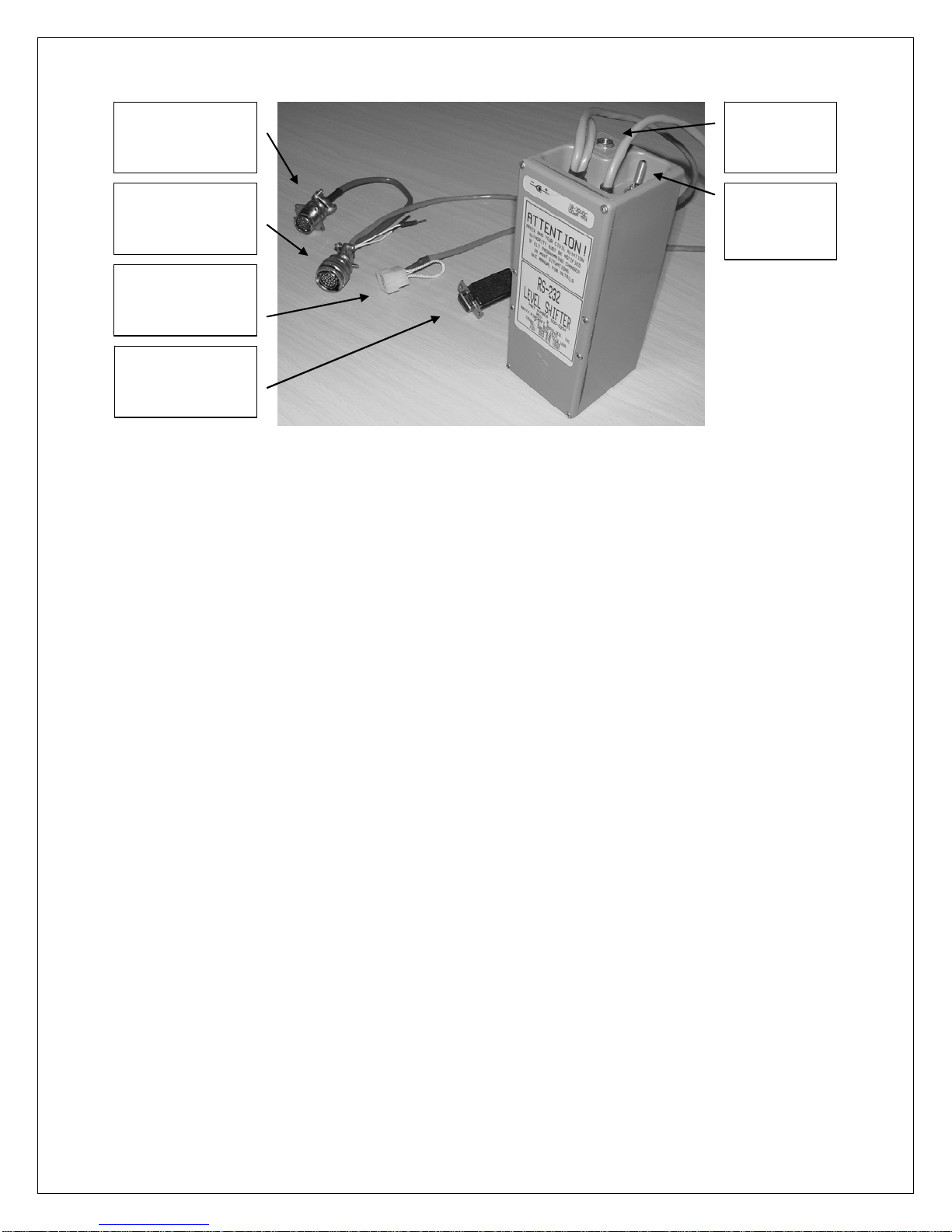
3.1 Level shifter installation.......................................................................................................1
3.2 “Artex” software installation................................................................................................2
3.3 “Artex” software uninstallation............................................................................................2
4Hardware Operation..........................................................................................................3
5Software Operation............................................................................................................3
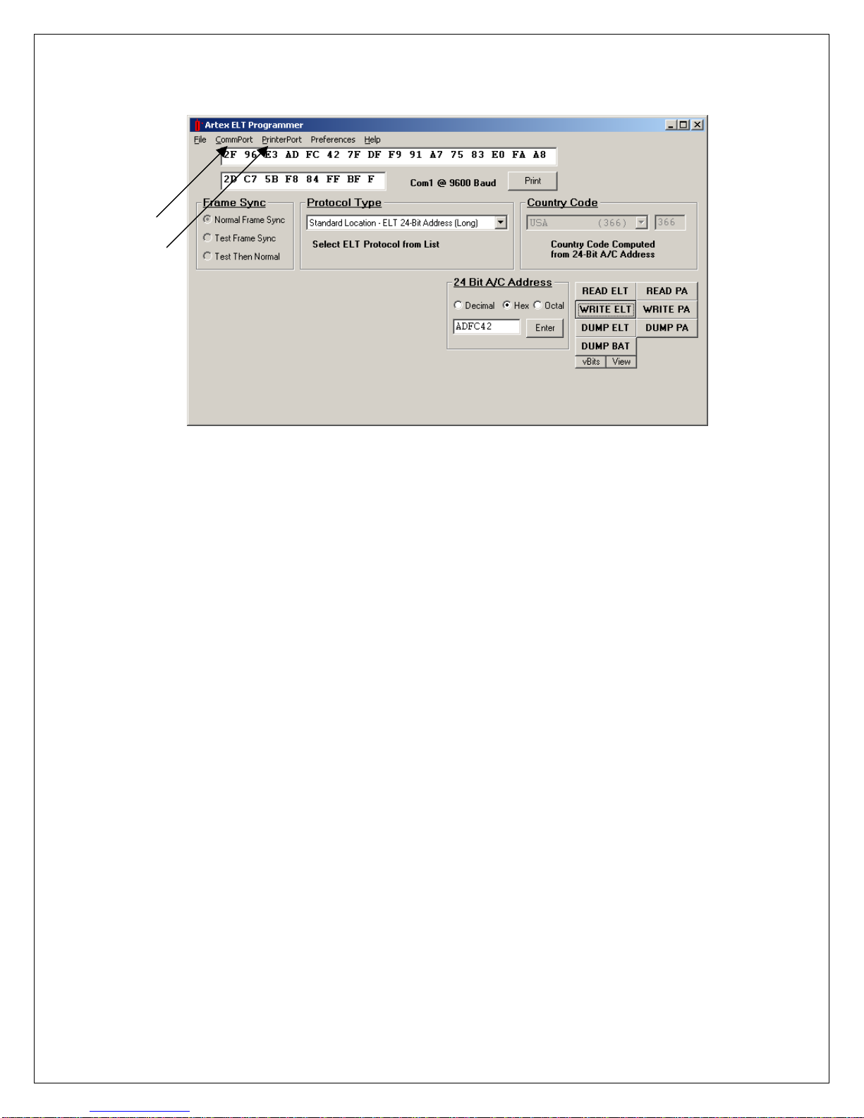
5.1 Software Overview...............................................................................................................3
5.2 Initial start up .......................................................................................................................4
6ELT Programming.............................................................................................................4
6.1 Start Up ................................................................................................................................4
6.2 ELT Programming ...............................................................................................................5
6.3 TABLE 1 ELT Data.............................................................................................................6
6.4 Printing ELT Programming Data.......................................................................................15
6.5 Software Exit......................................................................................................................16
7Programming the C406-N series PA (Programming Adapter)....................................16
7.1 Hardware Operation...........................................................................................................16
7.2 Software Operation ............................................................................................................18
8Processing..........................................................................................................................19
8.1 Normal ELT Processing Procedure....................................................................................19
8.2 Processing Procedure for ELT’s to be used with the Artex ELT/NAV INTERFACE auto-
reprogramming function or the C406-N series PA auto-reprogramming function............19
8.3 C406-N Series PA Processing Procedure ..........................................................................20
9Programming Verification ..............................................................................................20
9.1 INSTRUCTIONS...............................................................................................................20
10 Labeling Requirements....................................................................................................24
11 Registration Requirements..............................................................................................24
11.1 Civil Aviation Authority registration requirements...........................................................24
11.2 Artex Aircraft Supplies registration requirements.............................................................25
12 Technical Assistance ........................................................................................................25
13 Glossary of Software Functions......................................................................................26
14 Glossary of Software Errors and Error Messages........................................................28
Page i
15 ARTEX 406 MHz PROGRAMMING RECORD .........................................................29

Revision History
Manual Revision Engineering Change Order Date
- Release 05/30/01
A EC0 1211 08/17/99
B ECO 1340 03/03/00
C DCN 1704 05/25/01
D DCN 2168 03/24/03
D DCN 2285 09/15/03
E DCN 3173 02/25/08
F DCN 3275 08/14/08
F DCN 3448 06/04/09
G DCN 3466 08/10/09
G DCN 3548 11/02/09
G DCN 3357 01/26/09
Page ii

ARTEX AIRCRAFT SUPPLIES Document # 570-2225
Page iii
NOTICE:
This document is for use with the RS 232 Level
Shifter-Part Number 500-0232.
If programming using the Handheld Programmer-
Part number 453-2000, follow the procedures as
outlined in Document Number 570-2000.

1 Hardware and Software Package
131-0009 9 Volt Batteries
500-0232 RS-232 Level Shifter
500-8000 PA-PI, Modified
510-0406 CD-ROM Disk
570-2225 Repair Station Manual for 406 MHz ELT Programming
571-0017 Battery Replacement Instructions
611-0099 ME406 Programming Adapter
1600 “Temporary” 24 Bit Address Assignment Form
6178 Country Code List
Note: A 406 MHz Beacon Tester is not included in this package but is necessary to
test newly programmed ELT’s. Either the Sartech ARG 5410 (Artex P/N 453-0131
available in Kits 455-9010-01, 455-9010-02, 455-9010-03 or 455-9010-04) w/ coax,
and attenuator or Artex ETS (Artex P/N 453-1000 available in Kit 455-9100) or an
equivalent test set may be used. Contact the Artex Sales department for details and
current availability.
Note: A 121.5 MHz receiver is not included in this package but is necessary to
monitor ELT’s during programming.
2 Computer Requirements
The 510-0406 programming software requires an IBM-compatible PC with a Microsoft
Windows 95™ or newer operating system installed.
The PC should have a keyboard, mouse, color monitor, and CD-ROM.
The PC should have 10 megabytes of HD space free and available.
The PC should have a local or network printer available. A local printer not configured
through Windows 95™ must be installed on LPT1 or LPT2.
The PC should have one available 9-pin male serial (COM) port on the host computer.
If a 9 pin male serial port is not available, a 25 pin male serial port may be used with a
25-pin female-to-9 pin male adapter. The programming software requires that the serial
port used be either COM1 or COM2.
3 System Installation / Removal
3.1 Level shifter installation
If batteries are not installed, install batteries or attach external power supply that matches
ratings on Level Shifter label. Close case.
With the host computer off, plug Level Shifter 9 pin female connector into the host
computer’s COM1 or COM2 serial port. Use a 25-pin female-to-9 pin male adapter if
the only available port is the 25 pin male type. Do not confuse a 25 pin male serial port
with a 25-pin female printer port.
Page 1

ARTEX AIRCRAFT SUPPLIES Document # 570-2225
On-off
switch with
indicator
9-pin connector
to host computer
COM port
12-pin Molex
connector to ELT
(ME406 Adapter (not
shown
)
connects here
22-pin circular
connector to ELT
22-pin circular
connector to PA Optional
external
power jack
3.2 “Artex” software installation
Exit from all running Windows programs.
Insert the 510-0406 CD-ROM disk into the host computer’s CD-ROM drive. The
following instructions will assume the CD-ROM drive is “D:”. If it is not, replace “D:”
with the appropriate CD-ROM drive designation.
Click on the “Start” menu, and then click on “Run…”
Type “D:\Setup.exe” without the quotation marks in the box provided, or use the browse
button to select the D: drive and then the “Setup.exe” file.
Select “OK” to begin the installation software.
Follow the on-screen instructions to complete the software package installation. The
installer will ask for your name and company, a directory (folder) to place the new
software package in, a location in the Start Menu / Programs SubMenu to place a
shortcut at, etc.
When finished with the installer program, reboot the computer if required. The “Artex”
software is now ready for use.
3.3 “Artex” software uninstallation
Do not perform this operation now. This information is provided in case it is necessary
to uninstall the “Artex” software at a later time.
Select the Start Menu – Settings – Control Panel
Select Add/Remove Programs
Select “Artex” from the list of installed programs
Select the Add/Remove button. Answer “Yes” to the on-screen verification.
Page 2
If the Uninstall program detects any shared files that are no longer in use, it will ask if
they should be deleted. Artex has successfully deleted comct332.ocx, mscomctl.ocx,
mscomct2.ocx, and ikbutton.ocx. Artex has deleted other files such as “.dll” files that
appeared at this prompt and suffered consequences. Therefore, unless disk space is
almost full or disk backups are available, Artex does not recommend deleting any files at
this prompt. Select the appropriate response button.

ARTEX AIRCRAFT SUPPLIES Document # 570-2225
If the “Artex” software has been run, the Uninstall program will have missed a file
called “Artex.ini” and a shortcut called “bcn”. These files are in the destination
directory (folder) chosen during installation, likely to be C:\Program Files\Artex. It may
have missed a few BCNCodes files in the \Noaa subdirectory as well. Remove all of
these files manually.
You may need to reboot the computer to have the Start Menu reflect the fact that the
program has been removed.
4 Hardware Operation
The 500-0232 Level Shifter performs a simple but crucial function for communication with
an Artex 406MHz style ELT. It inverts and raises the data signal from the ELT to an RS-
232 signal level. This enables the ELT to talk to a personal computer for programming or
diagnostic purposes. It also enables programming of the C406-N series PA (Programming
Adapter) add addressed in a following section.
To use, the Level Shifter must simply be plugged into the front connector of an ELT (and/or
PA for C406-N series), plugged into the serial (COM) port of the host computer, and turned
on at its ON-OFF switch. It is important to note that the red LED on the Level Shifter’s
ON-OFF switch indicates on/off status and battery status. When the battery level drops to
an unacceptable level (and is about to cause failures), the LED will not illuminate, and
the battery should be replaced. Be sure to keep the Level Shifter off when it is not in use.
5 Software Operation
Page 3
5.1 Software Overview
The “Artex” software program is a custom package designed to simplify reading and
programming data to and from Artex ELT’s. The “Artex” program builds a custom
406MHz hex message for the user from simple data input provided by the user. This may
then be programmed into the ELT. The “Artex” program allows the user to print the 406
MHz hex message and its decoded breakdown for record keeping. If the user wishes, he or
she may also retrieve decoding information from an HTML decoding program provided by
Cospas-Sarsat, available at www.cospas-sarsat.org –beacons –beacon decode.

ARTEX AIRCRAFT SUPPLIES Document # 570-2225
5.2 Initial start up
The “Artex” programming software may be started by clicking on the “Artex ELT
Programmer” icon on the desktop or with the “Artex ELT Programmer” selection in the
Start Menu / Programs submenu. If the error message, “Unable to open selected COM
port” appears, hit “OK”.
The serial port that the Level Shifter will be connected to must be selected in software.
Select the CommPort menu and select the location where the Level Shifter is connected,
either COM1 or COM2. This setting will be retained even when the software is shut
down and computer turned off.
The printer location/selection must be set. The PrinterPort menu provides three options,
Windows Printer, LPT1, and LPT2. Chose the Windows Printer selection to use any
printer controlled by a Windows driver, including network printers. After making this
selection, a font window will appear. Select the font desired for use on the chosen
Windows printer. These settings will be retained. If a printer is attached directly to
LPT1 or LPT2, the “Artex” programming software will print raw text out these ports.
6 ELT Programming
Important: when working with any ELT, check that a 121.5MHz receiver is nearby, on, and
at adequate volume. This is necessary to catch and deactivate any ELT that may
accidentally be left on.
The ELT being programmed must properly perform all operations described in this set of
instructions. Any unit that fails any portion must be rejected and repaired.
6.1 Start Up
6.1.1 Check that a printer is connected to the proper printer port on the back of the computer or
via network. Check that computer and printer are on. From the Windows Desktop,
double-click the “Artex” icon. The programming window should now be open.
Page 4
6.1.2 The correct baud rate setting must be established. Current setting is indicated in the main
programming screen and under the CommPort menu. The baud rate must be set to 9600 to

ARTEX AIRCRAFT SUPPLIES Document # 570-2225
program long message ELT’s and 2400 to program short message ELT’s. See the grid in
section 6.2.1 for details. If the settings are incorrect, the ELT will not respond to
programming commands (an error message will say so). The baud rate may be changed
by clicking on the indication in the main programming window or under the CommPort
menu.
6.1.3 Plug the Level Shifter cable into the ELT. Turn Level Shifter on. Read notes below.
Important Note: A short message ELT (like the 110-406 series) with battery will activate
when the Level Shifter is turned on. Under many circumstances, it will not deactivate when
the Level Shifter is turned off. In this case, the ELT must be manually reset by moving the
switch to ON and back to OFF/ARM.
Important Note: When power is applied, a short message ELT will enter the transmit mode
and a weak 121.5/243MHz transmission may be heard. The 406MHz transmitter will be
active when the short message ELT’s battery is connected. If a battery is connected, do not
disconnect it. The remote case of a bad battery EEPROM that interferes with programming
may appear only if the battery is connected. This necessitates either programming the short
message ELT in a metallic enclosure to contain RF emissions, or completing the
programming and turning the level shifter off before the first 406MHz transmission in about
12-13 seconds. The level shifter should always be turned off promptly after programming to
minimize battery usage as well as possible 406MHz transmissions.
Note: If the following programming operations are done on a short message ELT during a
406MHz transmission burst, there is a very small chance that the burst will cause the
operation to fail. If this occurs, the user should simply try again, avoiding the transmission
periods (about 12-13 seconds after activation and then every 47.5-52.5 seconds).
6.2 ELT Programming
Refer to the chart (Table 1) on the following page as instructed to complete the
programming sequence below.
NOTE: For the following table, the protocols defined are as follows:
Std Location = Aircraft 24 Bit Address (Long) and ELT Serial (Long)
Aviation User = Tail Number (Short)
Serial User = Aircraft 24 Bit Addr (Short), Aircraft 24 Bit / National (Short), ELT /
COSPAS (Short), ELT / National USA (Short) and Aircraft Operator (Short)
National Location = ELT Serial (Long)
User Location = Aviation User / Tail Number / Location (Long)
Page 5
NOTE: Only Aviation User, certain Serial User and certain Standard Location protocols are
supported by default, additional protocols only available with specific Artex permission and
direction.

ARTEX AIRCRAFT SUPPLIES Document # 570-2225
6.3 TABLE 1 ELT Data
ELT part
number Description Baud
Rate Cospas-
Sarsat # Programmed
Serial # Supported
Protocols Model # Sequence #
range Production #
range
C406 Series
453-5060 C406-N 9600 135 Same as
unit label
(5 digit)
Std Location
Aviation User
Serial User
User Location
National
Location
7 0-1638 0-9
453-5061 C406-N HM 9600 135 Same as
unit label
(5 digit)
Std Location
Aviation User
Serial User
User Location
National
Location
7 0-1638 0-9
453-5000 C406-2 9600 See
Note 2 See
Note 2 Std Location
Aviation User
Serial User
6 0-1638 0-9
453-5001 C406-2HM 9600 See
Note 2 See
Note 2 Std Location
Aviation User
Serial User
6 0-1638 0-9
453-5002 C406-1 9600 See
Note 2 See
Note 2 Std Location
Aviation User
Serial User
6 0-1638 0-9
453-5003 C406-1HM 9600 See
Note 2 See
Note 2 Std Location
Aviation User
Serial User
6 0-1638 0-9
453-5006 C406-3 9600 See
Note 2 See
Note 2 Std Location
Aviation User
Serial User
6 0-1638 0-9
453-5056 RB406-1HM 9600 170 See
Note 2 Std Location
Aviation User
Serial User
6 0-1638 0-9
PA SERIES
453-5068 PA (Blank) 9600 135 Same as
unit label
(5 digit)
Std Location
Aviation User
Serial User
User Location
National
Location
7 0-1638 0-9
453-5078 PA (Pre-
Programmed) 9600 135 Same as
unit label
(5 digit)
Std Location
Aviation User
Serial User
User Location
National
Location
7 0-1638 0-9
Page 6

ARTEX AIRCRAFT SUPPLIES Document # 570-2225
G406 SERIES
ELT part
number Description Baud
Rate Cospas-
Sarsat # Programmed
Serial # Supported
Protocols Model # Sequence #
range Production #
range
453-5100 G406-1 9600 126 Same as
unit label
(5 digit)
Std Location
Aviation User
Serial User
6 0-1638 0-9
453-5102 G406-2 9600 126 Same as
unit label
(5 digit)
Std Location
Aviation User
Serial User
6 0-1638 0-9
453-5012 G406-4 9600 See
Note 2 See
Note 2 Std Location
Aviation User
Serial User
5 0-1638 0-9
B406 SERIES
ELT part
number Description Baud
Rate Cospas-
Sarsat # Programmed
Serial # Manufacturer # Model # Sequence #
range Production #
range
453-0004 B406-1 2400 67 Same as
unit label
(7 digit)
Aviation User
Serial User
(Short Only)
3 0-1047 0-255
453-0005 B406-A 2400 67 Same as
unit label
(7 digit)
Aviation User
Serial User
(Short Only)
3 0-1047 0-255
453-0003 B406-2 9600 104 Same as
unit label
(5 digit)
Std Location
Aviation User
Serial User
5 0-1638 0-9
453-5004 B406-4 9600 See
Note 2 See
Note 2 Std Location
Aviation User
Serial User
6 0-1638 0-9
110-406 SERIES
453-0406 ELT 110-406 2400 67 Same as
unit label
(7 digit)
Aviation User
Serial User
(Short Only)
1 0-1047 0-255
453-0407 ELT 110-406HM 2400 67 Same as
unit label
(7 digit)
Aviation User
Serial User
(Short Only)
2 0-1047 0-255
453-0421 ELT 110-406
NAV 9600 104 Same as
unit label
(5 digit)
Std Location
Aviation User
Serial User
5 0-1638 0-9
453-0423 ELT 110-406HM
NAV 9600 104 Same as
unit label
(5 digit)
Std Location
Aviation User
Serial User
5 0-1638 0-9
453-0006 ELT 110-406ED 2400 67 Same as
unit label
(7 digit)
Aviation User
Serial User
(Short Only)
4 0-1047 0-255
453-0424 ELT 110-406ED
NAV 9600 104 Same as
unit label
(5 digit)
Std Location
Aviation User
Serial User
5 0-1638 0-9
Page 7

ARTEX AIRCRAFT SUPPLIES Document # 570-2225
ME406 SERIES
ELT part
number Description Baud
Rate Cospas-
Sarsat # Programmed
Serial # Supported
Protocols Model # Sequence #
range Production #
range
453-6603 ME406 9600 See
Note 2 See
Note 2 Std Location
Aviation User
Serial User
User Location
National
Location
8 0-1638 0-9
453-6604 ME406HM
9600 See
Note 2 See
Note 2 Std Location
Aviation User
Serial User
User Location
National
Location
8 0-1638 0-9
453-6611 ME406P
9600 See
Note 2 See
Note 2 Std Location
Aviation User
Serial User
User Location
National
Location
8 0-1638 0-9
453-6650 ME406 BLACK
9600 See
Note 2 See
Note 2 Std Location
Aviation User
Serial User
User Location
National
Location
8 0-1638 0-9
Note 1: When entering data into the programming software, most fields not filled with
the maximum allowable number of characters will fill the unused portion with zeros to the
left of the data entered. Exceptions to this are noted in the appropriate sections below.
Note 2: The Cospas-Sarsat 15-digit ELT Identifier allows manufacturers 16,383 possible
serial numbers. Artex has reached that limit with these ELT’s.
For ELT’s that pass the 16,383 Serial number and move on to a 3-digit prefix, two different
Cospas-Sarsat numbers will be assigned to that ELT. In this case Cospas-Sarsat number
112 is used for Manufacturing Serial number 00001 to 16,383; Cospas-Sarsat number 170
is used for Manufacturing Serial number 170-00001 and above. The following chart shows
this:
C,B,G SERIES
ME SERIES
Page 8
Cospas-Sarsat # Manufacturing Serial # ELT Programmed Serial #
112 00001 to 16383 00001 to 16383
170 170-00001 to
170-16383 00001 to 16383
152 00001 to 16383 00001 to 16383
188 188-00001 to
188-16383 00001 to 16383
197 197-00001 to
197-16383 00001 to 16383

ARTEX AIRCRAFT SUPPLIES Document # 570-2225
Because a different Cospas-Sarsat # is used when the Serial numbers reset after 16,383,
the 15-digit ELT Identifier remains unique. Note: There were a small number of ELT’s in
the C,B,G series that used the letter “A” as a prefix before the numeral prefix was adopted
for use. (i.e. A00001 instead of 170-00001)
6.4
Note: When entering data into the programming software, most fields not filled with the
maximum allowable number of characters will fill the unused portion with zeros to the left
of the data entered. Exceptions to this are noted in the appropriate sections below.
6.4.1 The frame sync (message prefix) setting must be verified. This should always be set to
“Normal Frame Sync”. That corresponds to the 2F prefix in the 32 digit hex code. If this
setting is ever different from Normal Frame Sync, notify Artex Aircraft Supplies
immediately, as the ELT’s functionality depends on this setting. The other possible setting
is a test setting that corresponds to a D0 prefix in the 32 digit hex code. This setting will
cause the Search and Rescue monitoring system to ignore the ELT’s transmission,
dismissing it as a test message. A rescue effort will not begin.
Page 9
6.4.2 The desired programming protocol must be selected. Consult with local aviation
authorities for possible programming protocol exceptions/additional rules that may apply
for particular countries. In the “Protocol Type” dialogue box select the type of
programming desired by clicking on the down arrow or to its left to show the protocol
options. The chart in the above section will define which ELT’s are “Short Message”
ELT’s and which are “Long Message” ELT’s. Short message ELT’s accept short message
protocol programming only. Long message ELT’s normally use long message protocol
programming. They will accept short message protocol programming, though this is not

ARTEX AIRCRAFT SUPPLIES Document # 570-2225
typical. Some of the protocols seen below may not appear on your protocol list,
depending on access granted.
Aviation User – Tail Number (Short)
Serial User – Aircraft 24-Bit Address (Short)
Serial User – Aviation/ELT Cospas (Short)
Serial User – Aviation/ELT National - USA (Short)
Aviation User–Location – Tail Number (Long)
Standard Location - ELT 24-Bit Address (Long)
Standard Location - ELT Serial (Long)
National Location - ELT Serial (Long)
Any – Use BCNCODE To Create
If an ELT is to be programmed on a temporary basis for later update by the Artex ELT/NAV
Interface auto-reprogramming feature, refer to the Standard Location - ELT 24-Bit
Address (Long) section for temporary programming instructions.
If an ELT is to be programmed on a temporary basis for later update by a C406-N series
Programming Adapter auto-reprogramming feature, refer to the Serial User –
Aviation/ELT Cospas (Short) section for temporary programming instructions.
6.4.3 If Aviation User – Tail Number (Short) is selected (User protocol):
ELT's programmed with the short message protocol are not compatible with the
ELT/NAV Interface.
In the “COUNTRY CODE” dialogue box, select a country or type in the country code
number in the small box to the right. Only the proper country code number will be
shown and accepted if multiple numbers are assigned to a single country. Artex
document 6178 also lists valid country codes. When the code is correct, simply hit
“ENTER” on the keyboard or click in the “TAIL NUMBER” dialogue box.
Enter the tail number of the aircraft, which is up to seven alphanumeric characters.
Acceptable characters are letters (A-Z), numbers (0-9), a hyphen (-), a space ( ), and a
slash (/). If fewer than seven characters are entered, the software follows convention by
filling the remaining characters with spaces at the beginning. That will be reflected in
the final hex code. When finished, hit “ENTER” (screen or keyboard).
The 32 digit hex code is shown in the box at the top of the screen (24 active digits and 8
zeros filled in at the end for this short message), and the abbreviated 15 digit hex code is
shown in box beneath.
Click on the “WRITE ELT” button (or hit “ENTER” on the keyboard if the “WRITE
ELT” button is highlighted) to program the ELT. Close the temporary programming
window when programming is finished.
6.4.4 If Serial User – Aircraft 24-Bit Address (Short) is selected (User protocol):
ELT's programmed with the short message protocol are not compatible with the
ELT/NAV Interface.
Page 10
Select Cospas-Sarsat certification type in the “CERTIFICATION TYPE” dialogue box.
Cospas-Sarsat certification type is preferred over National certification type. Enter the
certification number appropriate to the type of ELT that is being programmed. This can

ARTEX AIRCRAFT SUPPLIES Document # 570-2225
be found on the chart above. If the customer specifically requires National certification
type, select it and enter the national code supplied by the customer.
Hit “ENTER” (screen or keyboard) or click on the “SERIAL NUMBER” dialogue box.
This particular serial number field represents the number of additional ELT’s on board
an aircraft (beyond the one primary ELT). It does not represent the ELT’s serial
number. Enter “0” unless otherwise directed by the customer.
Hit “ENTER” (screen or keyboard) or click on the “24 BIT A/C ADDRESS” dialogue
box. Select the correct number system (octal: 8 digits from 0-7, decimal: 7 or 8 digits
from 0-9, hex: 6 digits from 0-9 or A-F) to match the format of the 24 bit address
provided. Then enter the 24-bit address. You may then click on a different number
system selection to see the converted value. Note that the 3-digit country code is
automatically determined from the country data encoded in the 24 bit address.
Hit “ENTER” (screen or keyboard). The 32 digit hex code is shown in the box at the top
of the screen (24 active digits and 8 zeros filled in at the end for this short message), and
the abbreviated 15 digit hex code is shown in box beneath.
Click on the “WRITE ELT” button (or hit “ENTER” on the keyboard if the “WRITE
ELT” button is highlighted) to program the ELT. Close the temporary programming
window when programming is finished.
6.4.5 If Serial User – Aviation/ELT Cospas (Short) is selected (User protocol):
Note: ELT's programmed with the short message protocol are not compatible with the
ELT/NAV Interface.
Special case: If the ELT is to be used with the automatic re- programming function of
an Artex C406-N series Programming Adapter, this external device determines what is
programmed into the ELT. The final aircraft identification may not be known at the
time of ELT hex code reprogramming using the “Artex” software package. Artex
programs using Serial User – Aviation/ELT Cospas (Short) with a country code of 366
(USA), as the Programming Adapter will replace it with the correct aircraft identification
anyway.
In the “COUNTRY CODE” dialogue box, select a country or type in the country code
number in small box to the right. Only the proper country code number will be shown
and accepted if multiple numbers are assigned to a single country. Artex document 6178
also lists valid country codes. When the code is correct, simply hit “ENTER” on the
keyboard or click in the “COSPAS CERT #” dialogue box.
Enter the Cospas-Sarsat certificate number for the ELT being programmed. See the grid
above to match an ELT part number to the proper Cospas-Sarsat certificate number. If
the default Cospas-Sarsat certificate number is correct simply move on.
Page 11
Hit “ENTER” on the keyboard or click the “SERIAL NUMBER” dialogue box. Enter
the serial number in the “SERIAL NUMBER” dialogue box. Artex assigns this number.
For certain ELT models, it matches the ELT hardware serial number seen on the product
label. For other ELT models (especially new/future ELT models), this may not apply.
Check the table above for the “programmed serial #” assigned to the ELT’s part number.
Don’t forget to check for special programming rules unique to the country programmed.
If a country uses a “block” number format instead, it is entered here. Hit “ENTER”
(screen or keyboard).

ARTEX AIRCRAFT SUPPLIES Document # 570-2225
The 32 digit hex code is shown in the box at the top of the screen (24 active digits and 8
zeros filled in at the end for this short message), and the abbreviated 15 digit hex code is
shown in box beneath.
Click on the “WRITE ELT” button (or hit “ENTER” on the keyboard if the “WRITE
ELT” button is highlighted) to program the ELT. Close the temporary programming
window when programming is finished.
6.4.6 If Serial User – Aviation/ELT National - USA (Short) is selected (User protocol):
Note: This protocol is rarely used and should be used only after confirmation that a
particular country requires it. ELT's programmed with the short message protocol are not
compatible with the ELT/NAV Interface.
Note: “USA” implies that the National Use option of this type of protocol has been
selected, instead of Cospas-Sarsat certification data entry.
Make sure the “COUNTRY CODE” dialogue box indicates USA 366. This should be
automatic.
Make sure the “MANUFACTURER” dialogue box indicates 22 (ARTEX).This should
be automatic.
Enter a sequence number in the “SEQUENCE NUM” dialogue box. The ELT
manufacturer assigns this number. This number is typically the first four digits of the
ELT unit serial number, including zeros for unused places. Although this field can
accept values of 0-4095, Artex limits values to the range listed in the grid above. Now
hit “ENTER” on keyboard or click the “MODEL” dialogue box.
Enter the model number for the type of ELT being programmed in the “MODEL”
dialogue box. See the grid above to match an ELT part number to the proper model
number. Hit “ENTER” on keyboard or click the “PRODUCTION RUN” dialogue box.
Enter a production run number in the “PRODUCTION RUN” dialogue box. The ELT
manufacturer assigns this number. This number is typically the remaining digits of the
ELT unit serial number, after the first four. Artex limits values to the range listed in the
grid above. Hit “ENTER” (screen or keyboard).
The 32 digit hex code is shown in the box at the top of the screen (24 active digits and 8
zeros filled in at the end for this short message), and the abbreviated 15 digit hex code is
shown in box beneath.
Click on the “WRITE ELT” button (or hit “ENTER” on the keyboard if the “WRITE
ELT” button is highlighted) to program the ELT. Close the temporary programming
window when programming is finished.
6.4.7 If Aviation User–Location – Tail Number (Long) is selected (User-Location protocol):
Note: This protocol is only supported by ELT’s utilizing software version V136 or later.
ELT’s utilizing software version V135 or earlier should not be programmed with this
protocol.
Note: Long messages should never be programmed into short message ELT’s. See the
chart above for part numbers of short and long message ELT’s.
Note: Position resolution for this protocol is 4 minutes of longitude/latitude, whereas the
location protocols below offer resolution of 4 seconds longitude/latitude.
Page 12
In the “COUNTRY CODE” dialogue box, select a country or type in the country code
number in the small box to the right. Only the proper country code number will be
shown and accepted if multiple numbers are assigned to a single country. Artex

ARTEX AIRCRAFT SUPPLIES Document # 570-2225
document 6178 also lists valid country codes. When the code is correct, simply hit
“ENTER” on the keyboard or click in the “TAIL NUMBER” dialogue box.
Enter the tail number of the aircraft, which is up to seven alphanumeric characters.
Acceptable characters are letters (A-Z), numbers (0-9), a hyphen (-), a space ( ), and a
slash (/). If fewer than seven characters are entered, the software follows convention by
filling the remaining characters with spaces at the beginning. That will be reflected in
the final hex code. When finished, hit “ENTER” (screen or keyboard).
The 32 digit hex code is shown in the box at the top of the screen (24 active digits and 8
zeros filled in at the end for this short message), and the abbreviated 15 digit hex code is
shown in box beneath.
Click on the “WRITE ELT” button (or hit “ENTER” on the keyboard if the “WRITE
ELT” button is highlighted) to program the ELT. Close the temporary programming
window when programming is finished.
6.4.8 If Standard Location - ELT 24-Bit Address (Long) is selected (Standard Location
protocol):
Note: Long messages should never be programmed into short message ELT’s. See the
chart above for part numbers of short and long message ELT’s.
The cursor should be in the “24 BIT A/C ADDRESS” dialogue box. Select the correct
number system (octal: 8 digits from 0-7, decimal: 7 or 8 digits from 0-9, hex: 6 digits
from 0-9 or A-F) to match the format of the 24-bit address provided. Then enter the 24-
bit address. You may then click on a different number system selection to see the
converted value. Note that the 3-digit country code is automatically determined from the
country data encoded in the 24 bit address. Special case: If the ELT is to be used with
the automatic 24-bit address programming function of an Artex ELT/NAV
INTERFACE, the external device determines what is programmed into the ELT. The
final aircraft address may not be known at the time of ELT hex code reprogramming
using the “Artex” software package. Artex programs using the appropriate address from
document 1600 in this case, as the ELT/NAV INTERFACE will replace it with the
correct aircraft identification anyway. Because the programming is temporary, the 15
digit hex code field on the product label will be left blank. The country code labeled in
this special case is “999”, to indicate that an ELT/NAV INTERFACE does the final
(country specific) programming. See the section on labeling requirements for labeling
details.
Hit “ENTER” (screen or keyboard). The 32 digit hex code is shown in the box at the top
of the screen, and the abbreviated 15 digit hex code is shown in the box beneath.
Click on the “WRITE ELT” button (or hit “ENTER” on the keyboard if the “WRITE
ELT” button is highlighted) to program the ELT. Close the temporary programming
window when programming is finished.
6.4.9 If Standard Location - ELT Serial (Long) is selected (Standard Location protocol):
Note: Long messages should never be programmed into short message ELT’s. See the
chart above for part numbers of short and long message ELT’s.
Page 13
In the “COUNTRY CODE” dialogue box, select a country or type in the country code
number in small box to the right. Only the proper country code number will be shown
and accepted if multiple numbers are assigned to a single country. Artex document 6178

ARTEX AIRCRAFT SUPPLIES Document # 570-2225
also lists valid country codes. When the code is correct, simply hit “ENTER” on the
keyboard or click in the “COSPAS CERT #” dialogue box.
In the “COSPAS CERT #” dialogue box, enter the Cospas-Sarsat certificate number for
the ELT being programmed. See the grid above to match an ELT part number to the
proper Cospas-Sarsat certificate number. If the default Cospas-Sarsat certificate number
is correct simply hit “ENTER” on the keyboard or click on the “SERIAL NUMBER”
dialogue box.
Enter a serial number in the “SERIAL NUMBER” dialogue box, as assigned by Artex.
For certain ELT models, it matches the ELT hardware serial number seen on the product
label. For other ELT models (especially future ELT models), this may not apply. Check
the table above for the “programmed serial #” assigned to the ELT’s part number. Don’t
forget to check for special programming rules unique to the country programmed. If a
country uses a “block” number format instead, it is entered here. Hit “ENTER” (screen
or keyboard).
The 32 digit hex code is shown in the box at the top of the screen, and the abbreviated 15
digit hex code is shown in the box beneath.
Click on the “WRITE ELT” button (or hit “ENTER” on the keyboard if the “WRITE
ELT” button is highlighted) to program the ELT. Close the temporary programming
window when programming is finished.
6.4.10 If National Location - ELT Serial (Long) is selected (National Location protocol):
Note: Long messages should never be programmed into short message ELT’s. See the
chart above for part numbers of short and long message ELT’s.
In the “COUNTRY CODE” dialogue box, select a country or type in the country code
number in small box to the right. Only the proper country code number will be shown
and accepted if multiple numbers are assigned to a single country. Artex document 6178
also lists valid country codes. When the code is correct, simply hit “ENTER” on the
keyboard or click in the “SERIAL NUMBER” dialogue box.
Enter the serial number in the “SERIAL NUMBER” dialogue box, as assigned by the
ELT’s country of registry. Hit “ENTER” (screen or keyboard).
The 32 digit hex code is shown in the box at the top of the screen, and the abbreviated 15
digit hex code is shown in the box beneath.
Click on the “WRITE ELT” button (or hit “ENTER” on the keyboard if the “WRITE
ELT” button is highlighted) to program the ELT. Close the temporary programming
window when programming is finished.
6.4.11 If Any – Use BCNCODE To Create is selected:
ANY – Use BCNCode will automatically start the BCNCODES program to create the
hex code manually for any protocol not listed above. This is password protected so its
use is limited to those trained to program with BCNCodes directly.
After creating the hex code, press “F” to invoke the File List command. This places the
hex code data in storage so it can be transferred out to the “ARTEX” ELT programming
software.
Page 14
Press the “ESC” key 4 times to exit. Do not exit any other way. The “ARTEX” ELT
programming software assumes and requires that you use the “ESC” key to exit from
BCNCODES.

ARTEX AIRCRAFT SUPPLIES Document # 570-2225
The 32 digit hex code from BCNCODES is shown in the box at the top of the screen,
and the abbreviated 15 digit hex code is shown in the box beneath.
Click on the “WRITE ELT” button (or hit “ENTER” on the keyboard if the “WRITE
ELT” button is highlighted) to program the ELT. Close the temporary programming
window when programming is finished.
6.5 Printing ELT Programming Data
6.5.1 Check that a printer is connected to the printing destination that is selected under the
“PrinterPort” menu. To print the hex code that appears at the top of the main
programming window and a decoded breakdown of its meaning, click the “PRINT” button
with the mouse. This will provide a printout in the preferred format.
If BCNCODES is enabled, clicking the “PRINT BCN” button will print a BCNCodes
format printout to LPT1 or LPT2, only if the direct LPT1 or LPT2 printer port selection is
chosen. This does not work with Windows/network printers. This format is less preferred.
If a BCNCodes printout must be printed on a Windows/network printer, click the window
icon at the top left of the BCNCodes window to edit-mark, cut, and paste the screen into
another program for printing.
Page 15

ARTEX AIRCRAFT SUPPLIES Document # 570-2225
6.5.2 If a printer is not connected to the selected printer port, the software may lock up. If it will
not respond hit Ctrl-Alt-Del together. This will bring up a Windows task list. You should
see the software routine (called Artex ELT Programmer) on the list. Select it and chose
“End Task”. If prompted, chose “End Task” again. If this does not close the program
down, wait and then follow this sequence again.
6.5.3 After printing the ELT programming data, include the printout with a copy of the
“ARTEX 406 MHz PROGRAMMING RECORD” for this ELT. This form can be found
at the end of this manual. Details for its use will follow. Mark the box indicating that a
printout is attached to the programming record.
6.6 Software Exit
6.6.1 Select “EXIT” from the “FILE” menu or press and release “ALT” then “F” then “X” on
the keyboard.
6.6.2 Turn the level shifter off and disconnect it from the ELT.
7 Programming the C406-N series PA (Programming Adapter)
The C406-N series ELT’s offer an accessory programming adapter designed to reprogram
the attached ELT to match the programming contained within the programming adapter.
This feature is used by fleet operators to facilitate ELT exchange for maintenance purposes.
The C406-N series PA is programmed in exactly the same manner as an ELT, as described
in the section above.
A C406-N series ELT intended for use with the PA is typically shipped with generic Serial
User – Aviation/ELT Cospas (Short) programming as described in the ELT programming
section above and will be overwritten by the PA.
Page 16
7.1 Hardware Operation
Communication between the PA and the host computer using the 500-0232 level shifter and
510-0406 programming software requires translation by a C406-N series ELT or PA-PI. To
program a PA, attach it to the level shifter’s male 22-pin circular connector. Attach a C406-
N series ELT or PA-PI to the 22-pin female circular connector.
WITH CANNON PLUG ATTACHED TO PA:
Communication between the PA and the level shifter requires translation by a C406-N series
ELT or a Programmable Adapter – Programmer Interface (PAPI), P/N 500-8000.
Program a PA by attaching it to the level shifter using the cable P/N 611-0111. The male 22-
pin circular connector attaches to the PA and the cable 22-pin female circular connector
attaches to a C406-N series ELT or PA-PI.
Table of contents
Popular Software manuals by other brands

Philips
Philips BS03210 brochure

Symantec
Symantec WISE LINUX PACKAGE EDITOR 8.0 - REFERENCE... Reference

HP
HP CN088A - Serif PosterDesigner Pro quick start guide

EverFocus
EverFocus PowerVideo Plus user manual

RTS
RTS WKP-8 operating instructions

Juniper
Juniper JUNOSE 11.2.X PHYSICAL LAYER Configuration guide