ARUSNAVI ELECTRONICS ARNAVI BEACON User manual

Arusnavi LLC
ARNAVI BEACON
Autonomous satellite device for determining
and transmitting coordinates via GSM
network.
USER MANUAL
Version from 1.40

User manual [1.0] Page | 2
Content
GENERAL INFORMATION..........................................................................................................3
1.1 Using purpose ........................................................................................................................3
1.2 Working principle. .................................................................................................................3
1.3 External view of the device. ...................................................................................................4
1.4 Technical specifications. ........................................................................................................4
INSTALLATION GUIDELINESS..................................................................................................5
2.1 Installation procedure.............................................................................................................5
2.2 Installation guidelines ............................................................................................................6
2.3 Indication of the work ............................................................................................................7
CONFIGURATION........................................................................................................................8
3.1 Configuration via WEB-Configurator.....................................................................................8
3.3 Setting via PC ......................................................................................................................15
3.4 SMS, TCP commands ..........................................................................................................22

User manual [1.0] Page | 3
GENERAL INFORMATION
1.1 Using purpose
BEACON is a portable satellite device designed to determine the exact location of the tracking
object. Transmission of coordinates of the object is carried out by GPRS Protocol..
BEACON is used for:
1. Location determination of stolen vehicles.
2. Theft protection and detection of stolen vehicles.
3. Cargo monitoring and search in case of loss.
GPS/GLONASS navigation system is used to determine the location, in cases when the object
is in the zone of absence of GPS signal (underground Parking, garage box), the location is determined
using LBS positioning technology.
The device uses a standard battery size-AA . This allows the user to use any battery: simple
and specialized (included). The use of 3 batteries at the same time gives the beacon a high degree of
autonomy. Works up to 10 years of operation, using specialized batteries.
Convenient local configuration of the unit via USB via Configurator or remote configuration via
WEB-Configurator. The same functionality is supported for updating the device software.
1.2 Working principle.
The device detects its location and transmits location information via GSM (GPRS,
SMS and USSD) channels. Information about the location of the object is
displayed on the computer or mobile phone.
•Beacon "wakes up" only for short periods of time. This means that the beacon most
of the time does not consume battery power and does not emit radio signals, which
makes it the most autonomous device.
•The device has slots for two SIM cards of different mobile operators. The
presence of two SIM-cards increases the reliability of operation and reliability of
information transmission to the user.
•The device wakes up and notifies the owner of the location and transmits all
information about the status of the device (battery charge, speed, temperature, etc.)
to the user.
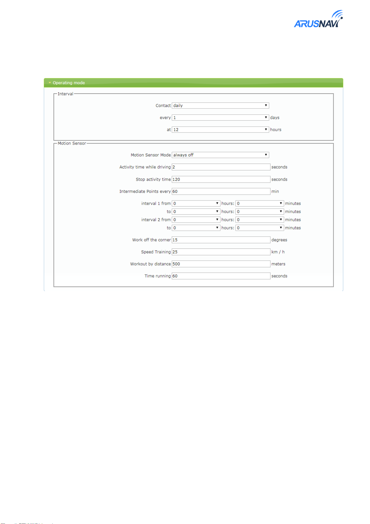
The beacon operates in three modes:
Interval - data transfer according to the configured interval.
Active - Automatically starts working at the same time with the vehicle movement and ends after
engine stop.
Online - works like tracker: working out the trajectory of the angle, speed, distance, time.

User manual [1.0] Page | 4
The device uses GPS/GLONASS satellite navigation system or LBS positioning (by mobile
operator towers) to determine the location.
1.3 External view of the device.
Picture 1
1.4 Technical specifications.
Table 1
Parameter
Value
Dimensions
Diameter 78 mm, height 23 mm
Case
Protected by IP67
Working temperature
from -40С to +85С
Batteries
Batteries type AA 3 pcs.
Connector’s type USB
micro-USB
Sleep mode energy consumption
No more than 1.2μA
Number of «wakes» (for one power set)
Up to 6000
Built-in motion sensor
Yes
BlueTooth
Yes
2 SIM-cards
2 SIM-cards nano-SIM, or 1 nano-SIM + SIM-
chip
Support USSD backup transmission
channel
Yes (For TopConnect mobile operator)
Worldwide connection
Yes (For TopConnect mobile operator)

User manual [1.0] Page | 5
INSTALLATION GUIDELINESS
Location of device elements on the board:
1. The nano-SIM slot 1.
2. The nano-SIM slot 2.
3. Debug button (force synchronization of settings
with web-configurator and sends the package to the
server).
4. Micro-USB connector (for diagnostics and
software update)
Picture 2
2.1 Installation procedure
Perform the initial configuration of the beacon using a USB connection.
Install one or two SIM cards if no SIM chip is installed. When installing two SIM
cards, consider that slot 1-has priority and will be used first.
Install batteries (3pcs.) (see the picture).
Before installation, make sure that the
batteries have no visible defects and the
terminal holders in the device do not have
traces of oxidation.
Next, check the indication that the device
started (if the indication was not forcibly
disabled in the settings).
Рисунок 3
Tighten the housing cover.
Install the device on the vehicle, taking into account the installation
recommendations.
12
3
4

User manual [1.0] Page | 6
2.2 Installation guidelines
For the best signal reception from satellites, the beacon should be placed with the logo
embossed upwards. The location of the device under any other is acceptable. The body of the
lighthouse from the logo can not be obscured by metal objects.
ATTENTION! The beacon should not be placed near highly heated
parts of the car. Temperatures above + 80ºC may affect the stability
of the device.
The GLONASS/GPS satellite signal passes through plastic, door trim, but does not pass
through metal bodywork, metallic tinting, thermal coating and other metal objects.
After installation, it is mandatory to check the quality of signal
reception from GPS / GNSS satellites using a mobile application or
SMS commands..
The beacon operates on 3 AA batteries of a wide voltage range: each of the batteries can have a
voltage from 1.5 V to 3.7 V.
The beacon is protected by IP67, which means full dust resistance and protection from strong
water jets or short immersion in water. This makes it possible to install the beacon on unprotected
from external influences areas of the car.
The body of the beacon provides the following method of installation: the beacon can be glued to a
double-sided tape from the side opposite to the logo. The side with the logo is shown on picture 4.
Picture 4.

User manual [1.0] Page | 7
2.3 Indication of the work
The beacon has an led indicator that can work in several modes:
0-do not use
Turn off the led at all and show no indication
1-device start indication
When you exit sleep mode to make a series of flashes (5-10 PCs)
2-device operation indication
In addition to the start display, show the overall operation of the device
short flash navigation
0 module is disabled
1 module is enabled, search for satellites
2-min number of satellites found
3-satellites found, excellent reception
long flash - GSM
0 module is disabled
1-module included, network search
2-connect to server
3-data transferred to the server
The indication is usually required at the time of beacon setting or at the time of installation. After
installation, the display can be turned off to save energy.
To do this, use one of the configuration methods (see " configuring the beacon»)
In the WEB-Configurator, set the led mode to "do not use", then send a command to update the
settings or wait for the settings to be updated according to the schedule.
Using a text command:
parameter (#43)
Indication led. 0-do not use
1-device start indication,
2-device operation indication,
123456*SETP*#43=0

User manual [1.0] Page | 8
CONFIGURATION
3.1 Configuration via WEB-Configurator
A WEB-Configurator is a cloud service for remote configuring or updating the software of a
device or group of devices without physically connecting.
For using the web Configurator, you need an account (login / password), which can be
obtained from the technical support service support@arusnavi.ru.
On the website http://ws.arusnavi.ru you have to enter your username and password to locate
the device ID or IMEI in your personal account using the search button, which is located in the
lower left corner of the panel:
Picture 6
Please press to open beacon settings:
Picture 7

User manual [1.0] Page | 9
Section «Operation mode»
The section allows you to configure the parameters of the beacon in different modes.
Picture 8
Interval mode:
The device operates in the interval mode by default, i.e. the <motion sensor Mode> parameter is in
the " off " state, and trajectory testing is not available. Determination of coordinates and
communication is carried out strictly with a specified time interval. The interval output does not
depend on other modes of operation - it can work in parallel with them or can be disabled.
<Output mode> - set the time period between the outputs of the device in the interval mode.
Available modes: do not contact, daily, minute, hour.
Active mode:
The active mode is triggered by the motion sensor and identifies events such as: the beginning
of the movement and the end of the movement. At any of these events, the beacon will communicate
and transmit coordinates.
If the device is connected at an interval during Parking, the satellite modem will not be started
in order to save energy and the previous valid coordinates will be transmitted to the server. Thus, the
coordinates will be fixed by the motion sensor.
The active mode can be automatically started for one or two selected time intervals during
the day, the rest of the time the beacon will be in interval mode or sleep mode.

User manual [1.0] Page | 10
<Motion sensor mode> - allows you to set the motion sensor to the following States: off,
always on, on in interval 1, on in interval 2, on in interval 1 and 2, online mode.
<Driving activity time> - the duration of continuous movement of the vehicle in seconds to
record the fact of the beginning of the movement. Valid values: (1-600) of seconds (Recommended
not more than 4 seconds).
<Stop activity time> - the duration of a continuous stop of the vehicle in seconds to record the
fact of a stop. Valid values are (1-600) seconds.
<Interval 1>, <Interval 2> - configurable time intervals for active mode.
Online mode:
To activate the mode, you must translate
<Mode motion sensor> in a mode "online".
While driving, the device does not turn off the GSM and navigation modules, communication with
the server is maintained constantly. During Parking, the device captures the coordinates ofthe motion
sensor and goes into"sleep mode".
In this mode, the beacon combines 2 works: by the motion sensor and by the trajectory in several
parameters:
<Angle contribution>- If the angle change between the rate of the last position that was sent to the
server and the current rate exceeds the specified value, the current position will be sent to the server.
Valid values are: (1-180)о.
<Speed contribution>- If the change between the speed at the time of determining the last position
that was sent to the server and the current speed exceeds the specified value, the current position will
be sent to the server. Valid values are: (1-250) km/h.
<Distance contribution>- If the distance between the last position that was sent to the server and the
current position exceeds the specified value, the current position will be sent to the server. Valid
values are: (1-5000) meters.
<Time contribution> - The time interval between the last and the next data sending to the server when
vehicle is parked. Valid values are: (1-600) секунд.

User manual [1.0] Page | 11
Section «System set»:
Picture 9
<Managing password> - the password to authorize the device. Used for remote access, such as
sending SMS and TCP commands. Valid symbols are: 0-9, a-z, A-Z, ".", "-". The maximum length
is 10 symbols.
<Time Zone> - offset time relatively UTC. Valid values are: from -12 to 12.
<Location determination > - in the interval mode, in order to save power, it is recommended to
alternate the location determination via GSM and GPS. Can take values: always via GSM, always via
GPS, every second time via GPS, every third time via GPS, … , every 10 times via GPS.
<Motion sensor sensitivity > - motion sensor sensitivity threshold: the lower the value, the less
impact must be applied for the motion to be detected. Valid values are: 0-10.
<Maximum activity time > - maximum duration of the location in minutes. If valid coordinates are
not set after a specified time, the location will be determined by GSM cell towers. Valid values are:
(1-250) minutes.
<Synchronization of settings with WEB-Configurator > - the frequency with which the beacon
requests settings from the Web-configurator. Available modes are: «do not use», «at each start»,
«once a day», «once a week», «once a month», «once a year».
< Synchronization software with WEB- Configurator > - the frequency at which the beacon checks
for software updates. Available modes: do not use, at every start, once a day, once a week, once a
month, once a year.
<System SimSmartFix> - navigation data swap system via GSM channel to speed up satellite search.
Using this feature may cause a slight increase in traffic. Available modes are: «Do not use», «by
necessity».
<LED for displaying> - required at the time of beacon installation or calibration. After installation,
it is recommended to turn off the led to save energy. Available modes are: do not use, device start
indication, device operation indication.
<Temperature sensor correction> - constant offset of the temperature sensor's indication.. Valid
values are: from -25 to 25.

User manual [1.0] Page | 12
Section «Data transfer»:
Picture 10
The beacon can simultaneously transfer data to two servers and three phone
numbers. Depends on your needs, you have to specifysettings for one or more channels
of data loading. Server 1 and server 2 setting:
<DNS/IP> - server monitoring adress. Valid symbols are:
0-9, a-z, A-Z, ".", "-".
<Port> - monitoring server port. Valid values are: 1-65535.
Telephone directory:
<Telephone number> - phone number of any country and operator without spaces, brackets,
dashes. Valid symbols are: 0-9,"+".

User manual [1.0] Page | 13
Section «SIM-card setting»:
Picture 11
The device supports simultaneous operation of two SIM-cards. For each SIM-card,
individual data transfer settings are set, in particular, the permission to work in
roaming. When using two SIM cards, the first slot is the priority. The second SIM-card
is used in cases when the use of the first SIM-card is prohibited by the settings or the
attempt to communicate was failed.
<Mode> - permission to work in networks. Valid values are: «do not use SIM-card», «home network
only», «roaming only», « home and roaming».
<operator’s APN > - valid symbols are: 0-9, a-z, A-Z, ".", "-", "@".
<APN login> - valid symbols are: 0-9, a-z, A-Z, ".", "-", "@".
<APN password> - valid symbols are: 0-9, a-z, A-Z, ".", "-", "@".
<PIN > - valid values are: 0-9999.
<USSD balance request> - valid symbols are: 0-9, " * ", " # ".
<Balance request frequency> - modes: «do not use», «with every start», «once a day», «once a
week», «once a month», «once a year».
<USSD backup channel > - valid symbols are: 0-9, " * ", " # ".

User manual [1.0] Page | 14
Settings synchronization
At the top of the settings window, please click "save settings".
Picture 12.
Then in the general table of devices in the field "Status" there will be an entry "settings" which
shows that the new settings are set to the device, but they are not applied on the device yet. To apply
the new settings, send an SMS or TCP command. If the command has not been sent, the settings will
be downloaded during the next scheduled synchronization of the settings with the Web-Configurator.
The beacon has a debug button on board for downloading the settings from the WEB-Configurator
and generate a package with its subsequent unloading according to the settings.
The "settings" status will disappear when the device confirms receiving the settings.
Picture 13.
Software Updating

User manual [1.0] Page | 15
Picture 14.
For updating the beacon software, please:
* Select a device (check the box or select it)
* Open the "Install firmware for selected devices" tab»
* Select device type, firmware version and click " Apply»
The "firmware" entry will appear in the "Status" field in the General table of devices, which
shows that the device has a new firmware, but the update has not yet occurred. To update the software,
send an SMS or TCP command. If the command was not sent, the update will occur during the next
scheduled update check.
Similar to the settings update, the "firmware" status will disappear when the device confirms
the software update.
3.3 Setting via PC
«Beacon Configurator» app description
Picture 15
«Beacon configurator» app is required for local diagnostics and beacon configuration (via
wired USB connection). "Beacon configurator" displays in real time all the parameters characterizing
the operation of the device at the moment (see picture 15).

User manual [1.0] Page | 16
The status of the debug button. Clicking the button will download the settings from the web-
configurator and generate a package with its subsequent unloading according to the settings.
It means:
-button is pressed; - button is not pressed.
1. The reason of awakening
- other event, - interval,
2. Motion sensor status.
- no movement - movement
- operation error - sensor event
3. Basic information about the device: software version, IMEI, battery voltage,
current time and date, time of the next scheduled connection, temperature.
4. GSM unit. Displays information about GSM modem status (on or off),
connected SIM cards: signal strength, roaming, operator name.
- SIM-card in operation - SIM-card not detected
- SIM-card detected, not currently in use
- home area - roaming - no signal
4. GPS unit. Displays the status of the navigation module and data from it such
as: coordinates, number of satellites, etc.
5. Data submission status.
- no transmission - ready to send - sending - sent

User manual [1.0] Page | 17
- error sending
6. Logbook. Required for service and displays system information about the
operation of the device.
The application also has the following functions: device settings, software updates, viewing
the black box.
Setting via app
The procedure for configuring the beacon is discussed in detail in the section "Configuration
via web-configurator". Similar to the web-configurator, the settings menu has subsections: operating
mode, system settings, data transfer, SIM card settings..
Attention! Before viewing and changing the settings, the Configurator
will ask for the device password.
Picture 16

User manual [1.0] Page | 18
Picture 17.
Picture 18.

User manual [1.0] Page | 19
Picture 19.
Picture 20.
"Record to device" button applies the selected settings to the device, after which the beacon
automatically sends the settings to the web Configurator. If you are unable to connect to the
network when you save the settings, the settings will be synchronized the next time you connect.

User manual [1.0] Page | 20
The current settings can be saved to a separate file by clicking "Save to file". Saved settings
can be applied on another device using the "Read from file"button.
Software update
Press the "Change software" button to open the firmware selection window
(picture 21).
In the window select the required firmware in the format".rom" and click "Open".
After that, the updating process will be started.
The update process takes 10-15 seconds. Next, the window will notify you when
the firmware update is complete. (Picture 22).
Before updating please verify that the USB cable connection is secure.
USB connection disconnection during software upgrade is strictly
prohibited.
Picture 21
Table of contents
Other ARUSNAVI ELECTRONICS GPS manuals
Popular GPS manuals by other brands

Kenwood
Kenwood DNX8160S quick start guide

Garmin
Garmin Astro 220 owner's manual

Pointer
Pointer Cellocator CelloTrack LTE Plus Standalone overview

Audiovox
Audiovox NPD5500 - Navigation System - in-dash installation instructions

Garmin
Garmin GTN 625 pilot's guide

Safe Fleet
Safe Fleet Seon vMax Trac install guide