ARX MSX 8 User manual

MSX 8 Owner's Manual v 3 CE ©2010 ARX® MSX 8Owner'sManual v 3 CE ©2010ARX®
MSX 8
Active
Microphone/Line
Splitter
OWNER’S
MANUAL
ARX Systems Pty Ltd, PO Box 15,
Moorabbin, Victoria 3189, Australia
Phone: (03) 9555 7859 Fax: (03) 9555 6747
International Fax: +61-3 -9555 6747
On the Web: www.arx.com.au
Email: [email protected]
8
Warranty Service Procedure
Should it become necessary to have your equipment serviced under the terms of the
warranty, please follow these steps:
1. Call your ARX distributor for a Return Authorization (RA) number;
2. Carefully repack the unit, in its original packaging where possible, including a note
with a description of the problem, and a copy of the receipt showing date of purchase.
Attach these to the actual unit itself. Don’t forget to write your name and address
clearly, and include a phone number where you can be contacted during normal
business hours. Make it easy for our service technicians to contact you if they have a
question. Also, use plenty of packing material - better to be safe than sorry.
3. Send the unit freight prepaid to ARX Systems, at the address given you with your RA
number. We will pay the return freight when the serviced unit is returned to you.
4. We strongly recommend you insure the package. We can’t fix it if it gets lost! Send it
by UPS, Fedex, DHL or any similar service that can track the package. Parcel Post is
not recommended
If Warranty Registration Card is missing, please write to ARX in the country of purchase,
stating model and where purchased, or to ARX, PO Box 15, Moorabbin, Victoria 3189,
Australia.
INTERNATIONAL LIMITED WARRANTY
ARX Systems (ARX) warrants to the first purchaser of any ARX equipment that it is free from
defects in materials and workmanship under normal use and service. ARX’s sole obligation
under this warranty shall be to provide, without charge, parts and labour necessary to
remedy defects, if any, which appear within twelve (12) months from date of purchase,
and for a further twelve (12) months supply parts only.
This is our only warranty. It does not cover finish or appearance items, burned voice coils,
or if the equipment has been, in ARX’s sole judgement:
•Subjected to misuse, abuse, negligence or accident;
•Repaired, worked on, or altered by persons not authorized by ARX;
•Connected, installed, adjusted or used for a purpose other than that for which it was
designed. This includes running a speaker system with the ISC leads disconnected, or with
a non-ARX crossover, or with the wrong processor.
This warranty gives you and us specific legal rights and you may also have other rights which
may apply.

MSX 8 Owner's Manual v 3 CE ©2010 ARX® MSX 8Owner'sManual v 3 CE ©2010ARX® 7
Specifications
Signal / Noise Ratio -94dB
Distortion .008%20Hz-20KHz
Gain through unit Switchable0,+10,+20,+30,+40dB
MaximumOutput +24dB
Pad Switch –20dBattenuation
Phantom Power +48VDCslowturnon/turnoff
OutputImpedance 100OhmsElectronicallyBalanced
(Optional600OhmTransformerbalancingavailable)
Clip LED 1dBbeforeclipping
AC Mains Input FusedIECsocket
AC Power 100-120VAC 1amp
220-240VAC 0.5amp
Transformer Type Low-noiseshieldedtoroidal
Size 19”Wx 1¾”H x6”D
482 x 44 x 155 mm
Weight 5lbs (2.2 Kg)
Completeonlinedocumentation isavailableontheARXwebsite:
www.arx.com.au/msx8.htm
ARX® is aRegisteredTrade Mark of ARXSystemsPty Ltd. MSX8™is
atrademarkor ARX Systems Pty Ltd.Anyothernamesand trademarks
areusedforinformationpurposesonly,andnootherintentisexpressed
orimplied
Thissymbolindicates that a SlowBlowfuse
isusedinthisequipment. Replace with same
typeandvalueonly
Thissymbol is intendedto alert youto the
presenceofuninsulateddangerousvoltage
withintheproduct's enclosure that may beof
sufficientmagnitude to constitute arisk of
electricshock.
Thissymbol is intendedto alert youto the
presenceof importantoperatinginstructions
containedinthis owner'smanual
WARNING SYMBOLS USED
ON THIS EQUIPMENT
IMPORTANT - PLEASE READ THIS FIRST
THIS IS A DUAL VOLTAGE UNIT. IT IS ESSENTIAL THAT YOU CHECK THAT THE VOLTAGE
ON THE FUSEHOLDER COVER BELOW THE AC CONNECTOR ON THE REAR OF THE
CHASSIS IS SET CORRECTLY BEFORE CONNECTING IT TO AC POWER.
To change, pull fuseholder out and rotate 180o, then push in again. Do not insert power
cable into unit until voltage has been correctly set. Do not connect power cable to AC
power until voltage has been correctly set
THIS IS SET FOR 100 V
AC TO 120 V AC
OPERATION
THIS IS SET FOR 220 V
AC TO 240 V AC
OPERATION
Complieswith89/336/EECEMCDirective,
amendedby 92/31/EEC and93/68/EEC;
meetsthefollowingstandards:EN55013:
1990,Sections3.2and3.5,EN55020:1988,
Sections 4.3, 5.4, 6.2, 7.0, 8.0., and EN
60950:1994 LowVoltageDirective
ComplieswithAustralianStandardAS/N25
1053
Ourpolicyisoneofcontinuousimprovement,
andthereforedesignsmaychangewithout
notice.However,unless otherwise stated,
specificationswill always equalor exceed
thosepreviously given.

MSX 8 Owner's Manual v 3 CE ©2010 ARX® MSX 8Owner'sManual v 3 CE ©2010ARX®45
Front Panel Connectors and Controls
• A and B balanced XLR Output splits Channel 1. Pin 3 -, Pin 2 +, Pin 1 Ground (Standard:
electronic; Optional: transformer isolated)
• –20dB pad switch and status LED
• Channels 1 and 2 Link switch and status LED
• 48V Phantom Power switch and indicator LED
Rear Panel Connectors
• Balanced XLR Input Channels 1 and 2. Pin 3 –, Pin 2 +, Pin 1 Ground
• Gain DIP switches: 0dB, +10, +20, +30, +40dB
• Balanced XLR Main (FOH) Output (same wiring as Input) Channels 1 and 2
• Balanced XLR Monitor Output (same wiring as Input) Channels 1 and 2
• 12V DC DIN connector for applications requiring remote power
• IEC 3 pin AC connector and integral fuseholder. Replace fuse with correct value only:
100–120 V AC 1 amp, 220–240 V AC 0.5 amp.
Note: No connection to Audio ground on transformer balanced models (T/S and
T/ALL)
• Numberedmarkerpanel forlabellingmicrophonechannelassigns
• AC Power status LED
Channel2 connectorsandcontrolsidentical
Architects’ and Engineers’ Specifications
The Active Microphone/Line Splitter shall be a two channel unit in a steel chassis six inches (200mm)
deep and one rack unit (44mm) high.
Each channel shall have its input and two outputs on the rear panel plus two outputs on the front
panel. Each channel shall also have a 48V Phantom power switch on the front panel with an
indicator LED and a –20 dB pad switch with an indicator LED.
There shall also be afront panel switch with an indicator LED to link both channels, thereby
providing a maximum of 8 outputs from one input.
The Input headroom shall be +21dB, with a CMRR of better than 70dB, and the frequency re-
sponse shall be 10 Hz to 20 KHz, ±0.5dB.
The Output impedance shall be 100 ohms electronically balanced on all four outputs per chan-
nel. Additionally all outputs shall have the option of being transformer balanced.
The maximum Output level shall be +24dB, with a Signal to Noise ratio of –94dB unweighted. Total
Harmonic Distortion shall be 0.008% @ 0dB, 20 Hz to 20 KHz.
Gain through the unit shall be switchable to 0, +10, +20, +30, +40dB via rear panel switches.
AC power shall be supplied by a removable 3 pin mains cable, connecting to an IEC connector
with integral fuse and voltage change switch on the unit’s rear panel.
The Active Microphone Splitter shall be the ARX MSX 32.

MSX 8 Owner's Manual v 3 CE ©2010 ARX® MSX 8Owner'sManual v 3 CE ©2010ARX®63
Introduction
Thankyouforchoosingthis MSX 8 Active Microphone/LineSplitter.AswithallARXequipment, it has
undergoneextensivefactorycalibrationand ‘burn in’ before shipping. Toensurecontinuedtroublefreeuse,
pleasefamiliariseyourselfwith the contents ofthismanualbeforeusing the MSX 8.
About the MSX 8
Today’svenuesfaceagrowingneedtoprovideamultiplicityofaudiofeedsfrompresentations,conferenc-
es,orchestralperformances andlectures.
Theadventofdigitalbroadcasting,thegrowthofwebcastsanddirect-to-CDarchivinghighlightthe
deficienciesinaudiosplittingsystemsmorethan ever before. Whether the end productisabroadcastfeed
orCDsalesofanunrepeatablelecture,performanceorevent,theend-users’expectationsofaudioquality
arehigher than ever.Andthe MSX 8’schannellinking enables itto instantly become a1 to 8pressbox at
thepush of a button
Withtheserequirementsinmind, ARX has developed theMSX8ActiveMicrophone/LineSplittertodeliver
theperformancerequired bytoday’sstandardsofaudio production.
Activemicrophoneandlinesplittinghas a number of benefits overpassivesplitters:primarilytheseare
improvedsoundquality,noise figures comparable tothebestmicrophoneinputs,increasedresistanceto
RFI,anda consistent microphone load. Allofwhichtranslate into superb audioqualityforyourclients.
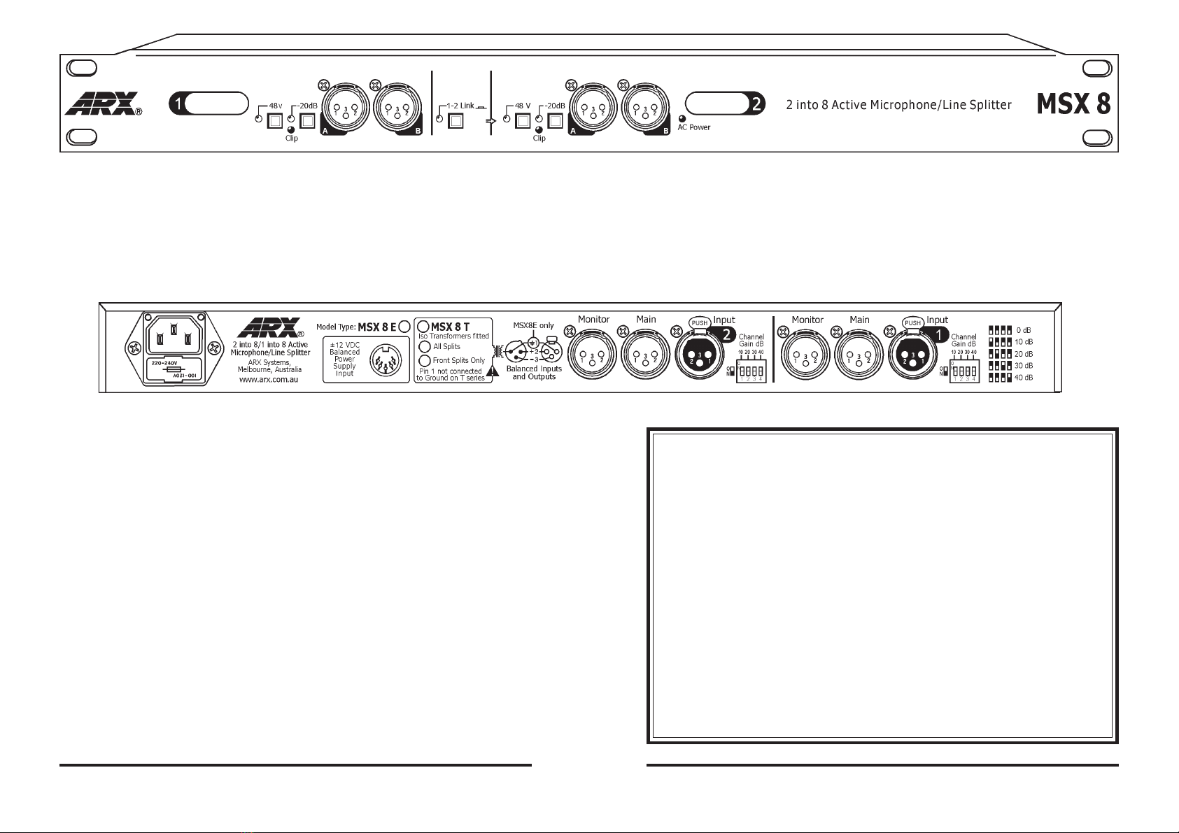
TheMSX8 consists of twochannelsofactively buffered ultra low noiseMicrophone/Line Splitter. Each of
thesechannels has four electronicallyBalancedsplits – two on therearpanel, plus twomoreon the front
panel.Allfour output splits havetheoptionof transformer balancing ifsospecified.
Eachchannelhasa–20dBpad switch and a silently switchable 48V PhantompowerwithindicatorLED.A
‘Link’switchlinks channel 1withchannel 2, providing amaximumof 8 Outputs fromasingle input. An
indicatorLEDshowswhenthisisactive. A Clip LED indicates imminent signaloverloadthroughthe
channel.
Gainthroughthe MSX 8canbe set individually bythesmall DIP switchesonthe rear of eachchannel,
from0dBthrough to +40 dBin10 dB steps
Anumberedmarkerpanel on thefrontprovidesaspacewhereindividualchannelconnections can be noted.
Internally,powerfulRFinputfilteringremoves both common mode and differential interferenceatultrasonic
frequenciesandabove. High CMRR isachievedwithprecisioncomponents,notvulnerable trimpots.
TheMSX8hasalownoiseshieldedtransformerbasedpower supply to obtain the maximum benefit from
theultra low noisedesign of the splittercircuitry.
Summingup,thefeaturepacked MSX 8 device is theanswerwherevertransparentsignalbufferingand
routingis required.
IMPORTANT
Checkthat the ACPower at thewall is inthe same voltagerange as thatprinted on thefuse holder door,
beforeconnectingthe MSX 8 totheAC supply. See Page2forfurther details.
Connecting the MSX 8
Theoriginalsignalfromthe microphone is connected intotheInputconnectoronthe rear panel of the
chosenchannel. From there itcan go anyorall of thefollowing:
1: To the main Front of house console, out of the Main connector on the rear panel
2: To the Monitor console (or a second Main console) out of the Monitor connector on the rear panel
3: To either of the two front panel splits, for connection to remote trucks, OB vans, recording feeds, press
feeds, etc. In normally supplied configuration these two splits are electronically balanced, identical to
the Main and Monitor feeds. However, they can be optionally fitted with isolating transformers where
complete signal isolation is required.
48VPhantompower can be switchedtothemic input from the frontpanel,and the channel Pad canbe
switchedintocope with ultra hotsignals.OverallChannelGain is controlled byeachchannel’sDIPswitch
onthe rear panel.Allswitches Off (down)equals a Gain of0dB. Only pushup the switch ofthe Gain
settingyou require. i.e. forachannel Gain of20dByou would push upswitch#2 only.
Ifmore splits froma single microphone arerequired, eg. foruse as aPress Box, then pushin the Link
switchon the frontpanel. The signalfrom Channel 1will then appearat all 8outputs of theMSX 8
MSX 8 Options
Eitherjustthe front panel splitsorall splits are available withisolatingtransformer balanced outputs if
required.Ideallythese should be installedatthe time of orderingtheunit(s),but they are availableasa
retrofittablekit. Contact ARX directlyorthe dealer at yourpointof sale forfurtherinformation on obtaining a
tranformerbalancingkit.The kit comes withcompletedetailsonthe installation, testing andgroundlift
wiringofthetransformers.
Note: Thisretrofittinginvolves opening thecaseof the MSX 8,soshould only be donebya qualified
technician.
MSX 8 ElectronicallyBalancedAllOutputs
MSX 8 T/S ElectronicallyBalancedMainandMonitorOutputs,
TransformerBalancedOutputs Splits1and2
MSX 8 T/ALL TransformerBalancedAllOutputs
Channel Gain setting
with DIP switches
This manual suits for next models
2
Table of contents
Other ARX Cables And Connectors manuals
Popular Cables And Connectors manuals by other brands

Senco
Senco JN91H1 operating instructions

Philips
Philips SWV3442W Specification sheet

Network Technologies
Network Technologies VOPEX-2V-H Installation and operation manual

Panduit
Panduit DP6 PLUS installation instructions

Fracarro
Fracarro SIG9506 operating instructions

Meltric
Meltric PN12c operating instructions