Asymtek TC V3 User manual

Conformal Curing Oven
TC V3
Operations Manual

P/N 7211567, Revision A English Translation based on French P/N 7211571, Rev. A ©2006
NOTICE
This is an Asymtek publication, which is protected by copyright. Original copyright date 2006. No part
of this document may be photocopied, reproduced, or translated to another language without the prior
written consent of Asymtek. The information contained in this publication is subject to change without
notice.
Manuals on the Internet
For the convenience of Asymtek customers and field service representatives, copies of Asymtek manuals
can be downloaded from:
http://www.asymtek.com/support/manuals.htm
Contact Us
Asymtek welcomes requests for information, comments, and inquiries about its products. Please contact
us using the information below:
Headquarters 2762 Loker Avenue West
Carlsbad, CA 92010-6603
USA
Toll Free: 1-800-ASYMTEK (1-800-279-6835)
Tel: +1-760-431-1919
Fax: +1-760-431-2678
Website: www.asymtek.com
Technical Support
USA: 1-800-ASYMTEK (1-800-279-6835)
Other regions:
www.asymtek.com Tech Support
Trademarks
Asymtek®is a registered trademark of Asymtek.
Nordson Electronics Systems® is a registered trademark of Nordson Corporation.

Table of Contents i
Table of Contents
1Introduction ......................................................................................................................................... 1
Overview ............................................................................................................................................... 1
Basic System Description...................................................................................................................... 1
2Safety.................................................................................................................................................... 3
Overview ............................................................................................................................................... 3
Facility Requirements............................................................................................................................ 3
Basic Safety Precautions and Practices ............................................................................................... 4
Safety of Personnel ....................................................................................................................... 4
Preventing Cure Module and Workpiece Damage........................................................................ 4
Earthquake Precautions........................................................................................................................ 5
Personnel ...................................................................................................................................... 5
Movement...................................................................................................................................... 5
Safety Warning Labels .......................................................................................................................... 5
Emergency Shutdown ........................................................................................................................... 5
Emergency Shutdown Recovery ................................................................................................... 5
Lockout of Electrical Energy.................................................................................................................. 6
Interlock ......................................................................................................................................... 6
3Components ........................................................................................................................................ 7
Overview ............................................................................................................................................... 7
Safety First ............................................................................................................................................ 7
Standard Module Components ............................................................................................................. 7
Conveyor System .......................................................................................................................... 7
Air Exhaust .................................................................................................................................... 8
Heating System ............................................................................................................................. 8
Reinforced Cooling System........................................................................................................... 9
Software ........................................................................................................................................ 9
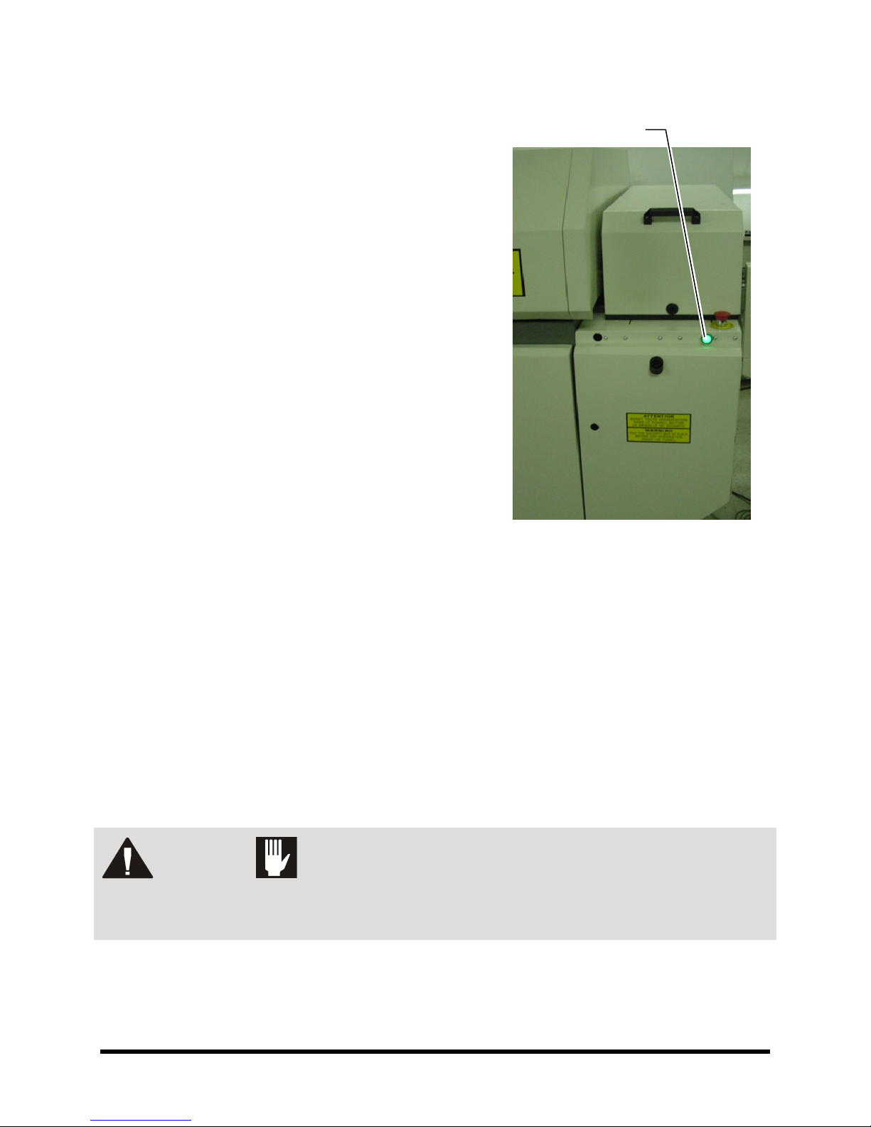
Light Beacon................................................................................................................................ 10
Optional Accessories........................................................................................................................... 13
Second Track Conveyor .............................................................................................................. 13
Heavy Duty Conveyor.................................................................................................................. 13
Automatic Conveyor Chain Lubrication ....................................................................................... 14
Dropped Board Detection Cell..................................................................................................... 14
Pin/Chain Conveyor 3 mm .......................................................................................................... 15
Board Counter Cell ...................................................................................................................... 15
Exit Jam Detection Cell ............................................................................................................... 15
4Installation ......................................................................................................................................... 17
Overview ............................................................................................................................................. 17
Safety First .......................................................................................................................................... 17
Facility Requirements.......................................................................................................................... 17
Unpacking and Placing the Cure Module............................................................................................ 17
Unpacking the Accessories ................................................................................................................. 18
Leveling the Cure Module ................................................................................................................... 19
Anchoring the Cure Module ................................................................................................................ 20
Connections ........................................................................................................................................ 20
5Operation ........................................................................................................................................... 21
Overview ............................................................................................................................................. 21
Safety First .......................................................................................................................................... 21
System Start-up................................................................................................................................... 21
System Shutdown ............................................................................................................................... 23
Hood Opening/Closing Operation ....................................................................................................... 24
Hood Opening Procedure:........................................................................................................... 24

ii Table of Contents
Hood Closing Procedure ............................................................................................................. 25
Setting Conveyor Clearance ............................................................................................................... 25
6Software ............................................................................................................................................. 27
Software Architecture .......................................................................................................................... 27
Main Menu........................................................................................................................................... 28
Tool Bar ....................................................................................................................................... 28
Zone Graphic View ...................................................................................................................... 29
Recipe Menu ....................................................................................................................................... 30
Recipe Management ................................................................................................................... 34
Control Menu....................................................................................................................................... 35
Inputs/Outputs ............................................................................................................................. 38
Conveyor Parameters Modifications ........................................................................................... 41
Set Date and Time Procedure.....................................................................................................43
Production Scheduling................................................................................................................. 45
Tactile Screen.............................................................................................................................. 47
Options Parameters Modifications .............................................................................................. 48
PLC Messages ............................................................................................................................ 49
Counters ...................................................................................................................................... 50
Alarms ................................................................................................................................................. 51
Resetting the Alarms ................................................................................................................... 52

Introduction 1
1 Introduction
This manual covers basic operations for the TC V3 Conformal Curing Oven. It is intended as a reference
for production operators, process engineers, service technicians, and persons unfamiliar with Asymtek
products.
Overview
This manual consists of the following sections:
•Safety
•Components
•Installation
•Operation
•Software
Basic System Description
The main features of the TC V3 Cure Module are:
•Five oven lengths (3.2, 3.8, 4.4, 5.6, and 7.4 m)
•Top and bottom radiant panel heating system
•Bottom extraction (TC 2400, TC 3000, TC 3600)
•Top blowing and bottom extraction (TC 4800, TC 6600)
•400 mm loading and unloading zone
•Chain conveyor


Safety 3
2 Safety
Overview
Operation of the TC V3 Conformal Curing Oven involves heat, electrical power, mechanical devices, and
the use of hazardous materials. It is essential that every person servicing or operating the Cure Module
fully understands all hazards, risks, and safety precautions described in this section. When properly
operated and maintained, the Cure Module should be safe and reliable.
This section is intended to provide basic safety information necessary for operating, maintaining, and
servicing your TC V3 Cure Module. This section covers the following topics:
•Facility Requirements •Safety Warning Labels
•Basic Safety Precautions and Practices •Emergency Shutdown
•Earthquake Precautions •Lockout of Electrical Energy
Use of this equipment in ways other than those described in the documentation supplied with the
equipment may result in injury to persons or damage to property.
To further optimize safe operation, maintenance, and servicing of the TC V3 Cure Module, precautions
and recommended practices are included with the procedures throughout this manual.
WARNING! Safety is considered a joint responsibility between the original equipment
manufacturer and the end-user (owner). Safety precautions and practices should
be in accordance with the governing laws and regulations, and facility
requirements in addition to those recommended in this manual.
WARNING! CAUTION!
Unsafe equipment conditions can result in personal injury or property damage.
Failure to properly operate and maintain the Cure Module in accordance with this
manual may jeopardize the built-in safety features.
Facility Requirements
To ensure optimal performance and safety, it is necessary to install the Cure Module in a facility that
meets the necessary requirements. Refer to the Installation section of this manual for detailed
instructions.

4 Safety
Basic Safety Precautions and Practices
The following precautions and practices are recommended during Cure Module operation and
maintenance.
Safety of Personnel
•Only trained personnel should be permitted to perform operation, maintenance, service, and
troubleshooting procedures.
•All personnel working on or near the Cure Module should know the location of all electrical
power supply sources.
•Lock/tagout procedures must be performed before service or maintenance work is done on
the Cure Module (see "Lockout of Electrical Energy" at the end of this section).
•Immediately push the red Emergency Off (EMO) button if personnel are in danger of
being injured.
•If in a confined room, ensure adequate and uninterrupted air ventilation, heating, and cooling
to meet environmental stress limits of personnel and the Cure Module.
•Follow MSDS recommendations for the proper handling, cleanup, storage, and disposal of
hazardous materials. Know the MSDS recommendations for treatment of injury resulting from
exposure to hazardous materials.
Preventing Cure Module and Workpiece Damage
•Immediately push the EMO button if the Cure Module or a workpiece is in danger of
being damaged.
•Use standard Electrostatic Discharge (ESD) precautions when working near ESD-sensitive
components. Always wear a grounding strap and connect it to the ESD ground before
handling workpieces.
•Follow all recommended system maintenance procedures as outlined in the Maintenance
Manual.
•Ensure that no air intake or exhaust grilles are blocked while the Cure Module is in operation.
WARNING! CAUTION!
Failure to comply with any of the safety recommendations could cause serious
injury to personnel and/or damage to the equipment.

Safety 5
Earthquake Precautions
In the event of an earthquake, the cure module must be secured to prevent movement that could cause
injury to personnel and damage to the equipment and facility.
Personnel
To prevent injury during an earthquake, all personnel should follow facility earthquake safety guidelines.
Movement
The TC V3 Cure Module is structurally designed to withstand seismic activity in accordance with industry
standards. To prevent system movement during an earthquake, each leveler (foot) should be anchored to
the floor with two bolts. The anchor joint should be able to withstand at least 100 kg (220 lbs.) of pullout
force. See "Anchoring the Cure Module" in the Installation Section.
Safety Warning Labels
Warning labels on your TC V3 Cure Module point out areas where personnel must use extreme caution to
prevent injury or damage.
WARNING! CAUTION!
Comply with all safety warning labels to prevent serious injury to personnel
and/or damage to the equipment. Worn or damaged labels should be replaced
with new labels having the same part number.
Emergency Shutdown
The TC V3 Cure Module features an EMO button that the operator or service technician can use to
immediately halt all system operations in case of emergency. This feature helps prevent injury to
personnel and damage to the Cure Module and workpieces being processed.
The EMO button is located on the front control panel of the cure module. The EMO cuts power to all
system components.
Emergency Shutdown Recovery
WARNING! CAUTION!
Do not restart the curing operation until the condition causing the emergency
shutdown has been remedied. Failure to comply could cause serious injury to
personnel and/or damage to the equipment.

6 Safety
To recover after an Emergency Shutdown:
1. Clear the Conveyor of all workpieces.
2. Lock out/tag out all system power. See "Lockout
of Electrical Energy" at the end of this section.
3. Locate and remedy the cause of the emergency
shutdown. If necessary, refer to the TC V3
Maintenance Manual for troubleshooting
information.
4. Reset the main circuit breaker inside the
electronics enclosure if it has been tripped.
5. Turn the red EMO button clockwise until it pops
back into position.
6. Remove all warning tags and locking devices.
7. Restart the Cure Module. See "System Start-up"
in the Operation section.
8. Wait at least 30 seconds then push the reset
button. Failure to do so could cause problems with
the motor speed controller.
9. Open the Alarm window and reset alarms on the
PLC. See "Resetting the Alarms" in the Software
section.
Figure 2-1 Reset Button
10. Click on the Start button on the Main Menu.
11. Wait for temperature stabilization before running production.
"NOTE The alarm will sound upon start up.
Lockout of Electrical Energy
TC V3 Cure Module electrical components have been designed in accordance with industry-wide safety
standards. However, precautions must still be taken whenever personnel may be exposed to the
unexpected power-up of the equipment or release of hazardous electrical, ultraviolet, or microwave
energy. Lock out and tag out electrical power before performing service or maintenance work on the Cure
Module.
WARNING! CAUTION!
All personnel working on or near the Cure Module should know the location of all
electrical power supply sources. Failure to follow lockout/tagout procedures could
cause serious injury to personnel and/or damage to the equipment.
Interlock
The Interlock is an electronic connection that immediately cuts power to any motion and pneumatic
actuators. If the hood or access doors are opened during production, the interlock is activated and all
curing activity immediately stops to protect the operator from injury.
Reset Button

Components 7
3 Components
Overview
This section provides a close look at standard equipment and optional accessories for your TC V3 Cure
Module. This section covers the following components:
•Standard Module Components
•Optional Accessories
Safety First
Before operating or performing maintenance on any of the equipment described in this section, please
review the important information provided in the Safety section.
Standard Module Components
Conveyor System
The Conveyor System moves items (PCBs, substrates, etc.) through the oven for thermal cycle
processing (Figure 3-1). It is adjustable by a hand crank (see Figure 5-5 in the Operation section).
Maximum product weight is 2 Km per meter.
CAUTION! The correct operation of the conveyor is not guaranteed if the product weight is
heavier than 2kg per meter. For heavier weight the "Heavy Duty Conveyor"
option is available.
The conveyor is composed of:
•electrical motor
•speed sensor
•frequency controller in close loop
•transmission chain
•2 main conveyor chains
Figure 3-1 Conveyor System

8 Components
Air Exhaust
The oven is equipped with an Air Exhaust circuit that can be connected to the factory exhaust
(Figure 3-2). During the curing process, varnish from the PCBs release heavy solvents. In order to avoid
solvent accumulation, it is necessary to evacuate the air inside the oven.
Figure 3-2 Air Exhaust
Heating System
The Heating System provides for the thermal cycle inside the oven. It includes six to ten zones,
depending on the oven length, that can be set to the determined thermal cycle.
The heating mode is composed of 70% radiation and 30% convection. The heating system provides
medium/long infrared radiation above and below the load. The heating tunnel is made up of resistors
protected by vitro-ceramic glass plates. The temperature is controlled by a thermocouple (K type).

Components 9
Reinforced Cooling System
The Reinforced Cooling System (Figure 3-3) blasts cold air through three directed-air knife fins by means
of an integrated helical fan inside the oven frame. The hot air is pulled through the perforated plenum by
an external fan (customer-supplied waste air exhaust).
Figure 3-3 Cooling System
Software
The Software control of the equipment is ensured by a complete SIEMENS PACKAGE (Figure 3-4) that
has the following characteristics:
Industrial PLC SIEMENS CPU IM 151 / 315 2DP
•SIEMENS 5”7 TFT Display
•Industrial SIEMENS Modem (Option)
•Auto diagnostic
•On-line help
•Alarm log & historical log capability
•Instruction and alarm management
•Storage capacity > 100 files
•SMEMA interface
•CE Approval certification
Figure 3-4 SIEMENS Software

10 Components
Light Beacon
The TC V3 Cure Module is equipped with a Light Beacon (Figure 3-5) that displays system status and
can warn the operator when fault conditions exist. The Beacon displays colored lights (green, orange, and
red) that can be solid or flashing, with an audible alarm capability to alert the operator of routine and
urgent tasks that require attention.
"NOTE The alarm will sound automatically for
certain conditions with action required
for the red light alarm.
Table 3-1 Light Beacon Colors
Color Condition
Green Equipment running okay.
Orange Oven is below defined temperature
or conveyor speed needs
stabilization.
Red At least one alarm has been
detected. Heat can be automatically
switched off depending on the
alarm.
Figure 3-5 Light Beacon

Components 11
Alarm Conditions
The following table describes each type of alarm, cause, oven condition, and restart condition.
Table 3-2 Alarm Conditions
Type of Alarm Cause Oven Condition Restart Condition
Speed Band
Alarm
The difference between the
measured speed and the
requested speed is higher
than the alarm speed defined
in the r.
Heat and conveyor on
Oven ready signal off
Orange tower light on
When the measured
speed is inside the
defined band.
Low Speed Alarm The measured speed is lower
than the low speed limit
defined in the recipe.
Conveyor on
Heat off
Oven ready signal off
Red tower light on
Alarm sounds
When the measured
speed is higher than the
low speed.
Reset the alarm.
High Temperature
Alarm 1
In any one zone the measured
temperature is higher than
300 °C for longer than 3 min.
Conveyor on
Heat off
Oven ready signal off
Red tower light on
Alarm sounds
When the measured
temperature is lower
than 300 °C.
Reset the alarm.
Temperature
Band Alarm
In any one zone the measured
temperature is outside of the
authorized band defined in the
recipe.
Heat and conveyor on
Oven ready signal off
Orange tower light on
When the measured
temperature is inside the
defined band.
Reset the alarm
Thermocouple
Short-Cut Alarm
There is not 10 °C of
temperature elevation on one
zone while more then 80% of
the power is applied.
Conveyor on
Heat off
Oven ready signal off
Red tower light on
Alarm sounds
When a temperature
elevation of 10 °C is
achieved in the specified
time (from 1 to 10 min.
according to the oven).
Reset the alarm.
Thermocouple
Broken Alarm
Thermocouple is broken Conveyor on
Heat off
Oven ready signal off
Red tower light on
Alarm sounds
When thermocouple is
reconnected.
Reset the alarm
Security Bar Alarm The security bar is not in
place within 15 seconds of
opening the hood.
Red tower light on
Alarm sounds
When security bar is
positioned and installed
alarm will stop.
Open Hood Alarm The closed hood sensor is still
detected after 15 sec of
opening the hood.
Red tower light on
Alarm sounds
Reset alarm.
Exhaust Alarm The input exhaust OK is
down.
Conveyor on
Heating off
Oven ready signal off
Red tower light on
Alarm sounds
When input exhaust OK
changes to 1.
Reset alarm.

12 Components
Type of Alarm Cause Oven Condition Restart Condition
Loss Conveyor
Parameters Alarm
The conveyor parameters are
lost.
Oven ready signal off
Red tower light on
Alarm sounds
When conveyor is
recalibrated (refer to the
Maintenance Manual)
PCB Spacing
Length Inferior
than PCB Hole
Max Length Alarm
PCB spacing length inferior
than PCB hole max length
Oven ready signal off
Red tower light on
Alarm sounds
When recipe parameters
are adjusted.
Reset alarm.
Dropped Board
Alarm (option)
The dropped board sensor is
activated
Heat and conveyor on
Oven ready signal off
Red tower light on
Alarm sounds
When the input exhaust
OK changes to 0.
Reset alarm.
Board Jam Alarm
(option)
The count sensor at the
conveyor output is sealed
longer than the maximum
delay defined in option
parameters menu.
Heat and conveyor on
Oven ready signal off
Red tower light on
Alarm sounds
When the sensor is not
activated.
Reset alarm.
Input Transfer
Alarm (option)
The delay between the “Send
PCB” signal from the
upstream machine and input
board sensor on the oven is
longer than the time defined in
the option parameters menu.
Oven ready signal off
Red tower light on
Alarm sounds
Reset alarm.
Output Transfer
Alarm (option)
During a delay, the
"downstream ready" signal is
down longer than the time
defined in the parameters
option menu.
Oven ready signal off
Red tower light on
Alarm sounds
Reset alarm.
Lubricator Alarm
(option)
The conveyor chain
lubrication oil level is below
the minimum level.
Alarm message received
Oven still in production
When oil level is raised.
Humidifier Alarm
(option)
There is a change in humidity
level.
Oven ready signal off
Red tower light on
Alarm sounds
When humidifier error
signal decreases to 0.
Reset alarm.

Components 13
Optional Accessories
Second Track Conveyor
The Second Track Conveyor option doubles the production capacity (Figure 3-6). Adjustable width is
identical for both conveyors:
•Minimum: 2 x 50 mm •Maximum: 2 x 200 mm
Figure 3-6 Second Track Conveyor
Heavy Duty Conveyor
The Heavy Duty Conveyor option is recommended for PCB or carrier weights over 2kg/m (Figure 3-7).
Features include a special rail shape and a dual chain to transport PCBs or carriers.
Figure 3-7 Heavy Duty Conveyor

14 Components
Automatic Conveyor Chain Lubrication
An Automatic Conveyor Chain Lubrication option is available to ensure optimal chain lubrication
(Figure 3-8). The lubrication module is located at the front of the cure module.
Figure 3-8 Automatic Chain Lubrication System
The lubrication oil tank and pump are built inside the cure module frame and ensure chain lubrication by a
drip mode. The lubrication cycle (frequency and quantity) is controlled by PLC. When the tank is nearing
empty a standard low level alarm will display.
Dropped Board Detection Cell
The Dropped Board Detection Cell is an optical cell that crosses the cure module from the input to the
output of the conveyor (Figure 3-9). If a dropped board is detected, the heat will automatically stop and an
alarm will sound.
"NOTE This option is not available for TC 4800 and TC 6600 Cure Modules.
Figure 3-9 Dropped Board Detection Cell

Components 15
Pin/Chain Conveyor 3 mm
The Pin/chain Conveyor length standard is 5 mm. A 3 mm length is available as an option (Figure 3-10).
For safety reasons this option is available only for 3.2, 3.8, 4.4, and 5.6 m total length ovens.
Figure 3-10 Pin/Chain Conveyor 3 mm
Board Counter Cell
The Board Counter Cell is an optical cell positioned to count the number of boards conveyed through the
oven and to count total PCB production (Figure 3-11). Counter cells are located at the input and output of
the oven.
Figure 3-11 Board Counter Cell
Exit Jam Detection Cell
The Exit Jam Detection Cell is an optical fiber detection cell located at the output of the oven to detect
potential board jams. This cell monitors the correct transition operation between the oven and the
downstream machine using timing defined by the supervision software. If a jam is detected, the heat is
turned off and an alarm will sound.

Table of contents