AT&T Z7308 H01B User manual

AT&T
CIB 3032
Z7308 H01B) ATTENDANT CONSOLE (3162)

CIB 3032
(Z7308 H01B) Attendant Console (3162)
The attendant console (Figure 1) is a console for a large communications
system. Up to 30 outside lines and 70 voice terminals may be accessed by
this attendant console.
Assembling Your Attendant Console
1.
Unpack the attendant console. The console has the following components:
●
●
●
●
●
attendant console body ●power supply kit, which
includes:
handset, with handset cord attached
modular voice terminal cord ●voice terminal power
supply
adapter plate ●power supply cord
desk stand ●Z400F adapter
See Figure 1 to identify these components.
handset
attendant
adapter plate
console body
handset cord
modular voice
terminal cord
Z400F adapter
power supply
cord desk stand
voice terminal
power supply
Figure 1.
Attendant Console Components
Attaching Adapter Plate
1.
2.
Turn the attendant console over.
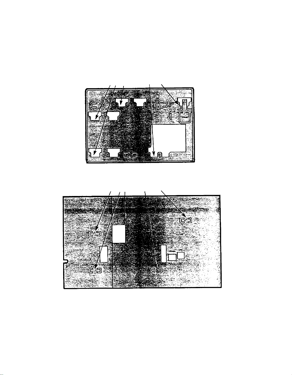
Attach the adapter plate to the bottom of the console by sliding the adapter
plate’s mounting slots under the attendant console’s mounting tabs (see
Figure 2). Make sure the largest opening on the adapter plate is over the
area for the “OTHER” and “LINE” jacks.
adapter plate mounting slots
ADAPTER PLATE
attendant console mounting tabs
ATTENDANT CONSOLE
Figure 2.
Mounting Tabs and Slots
NOTE: To remove the adapter plate press the tab marked “PRESS” and,
keeping the tab pressed, slide the adapter plate down until the attendant con-
sole’s mounting tabs are dislodged from the adapter plate’s mounting slots.

Mounting Your Attendant Console
1.
Check to see that your desk stand is adjusted to the lowest position. The
support bar (see Figure 3) should be in the groove for the lowest position
(see Figure 4). If it is not in the lowest position, adjust it now by following
the instructions in the next section, “Adjusting the Desk Stand”.
console mount
spring-loaded support bar
handle
Figure 3.
Desk Stand
low angle
middle anlge
support
bar
grooves
high angle
Figure 4.
Console Mount
(Bottom View)
2.
Position the top of the desk stand on the bottom of the attendant console
so that the mounting tabs on the adapter plate (see Figure 5) fit into the
“A” mounting slots on the stand (see Figure 6).

adapter plate mounting tabs
Figure 5.
Attendant Console with Adapter Plate
(Bottom View)
“A” mounting slots
Figure 6.
Desk Stand Mounting Slots
3.
Gently slide the stand upward so that the mounting tabs on the adapter
plate fit firmly into the smaller part of the three mounting slots on the desk
stand.
NOTE:
To remove the desk stand from the console, slide the desk stand down
until the adapter plate’s mounting tabs are dislodged from the desk stand’s
mounting slots.
Adjusting the Desk Stand
1.
2.
3.
4.
Grasp the handle on the spring-loaded support bar (see Figure 3).
Lift the console mount slightly (see Figure 3).
Put the bar underneath the groove for the appropriate position (see Figure
4).
Lower the console mount and let the support bar slide into the groove.

Attaching Cords to Console Body
Check to see that one end of the handset cord is attached to the hand-
set. If it is not attached, plug one end into the handset now.
1.
2. Plug the other end of the handset cord into the jack on the bottom right
corner of the console (see Figure 7).
WARNING: Do not plug the handset cord into the jacks labeled “LINE” or
“OTHER”.
modular voice terminal cord desk stand
handset
jack
jacks for
handset cord
Figure 7.
Attaching Cords to Console Body
3. Place one end of the modular voice terminal cord (marked D8W on its
jack) under the desk stand’s support bar and over the base of the desk
stand (see Figure 7). Plug it into the “LINE” jack on the bottom of the
attendant console.

Attaching Voice Terminal Power Supply
1.
Plug the modular voice terminal cord (marked D8W on its jack) into
the voice terminal jack on the Z400F adapter (see Figure 8).
voice
terminal
jack
power jack
modular voice
terminal cord
output jack
power supply cord
Figure 8.
Attaching Cords to Adapter
2.
3.
Plug one end of the power supply cord (marked D6AP on its jack) into
the power jack on the Z400F adapter. Plug the other end into the out-
put jack on the power supply (see Figure 8).
Plug the Z400F adapter into the building wiring connection (see Figure
9). This connection may be a modular terminal jack or a modular voice
terminal extension cord (marked D8AF on its jack).

modular voice terminal
extension cord (D8AF)
Z400F
adapter
OR
modular terminal jack
Figure 9.
Attaching Adapter to Building Wiring
4.
Refer to the exploded view in Figure 10 to make sure all the components
are installed correctly.
modular voice
modular voice terminal
terminal cord (D8W) extension cord
(D8AF)
Z400F
adapter
OR
power supply cord
(D6AP)
ac building wiring
connections
outlet power supply
Figure 10.
Completed Power Supply Installation
5. Plug the power supply into a 117-volt ac outlet.
NOTE: The 117-volt ac outlet should not be controlled by a switch.

Testing Your Attendant Console
The test/program (T/P) switch on the left side of the attendant console (see
Figure 11) can be used to test the lights and the ringer. It has three positions:
●
●
●
T– test position
center (dot)– normal operating position
P– programming position.
test/program speaker/ring
switch
volume control
Figure 11.
T/P and Volume Control Switches
After connecting the attendant console to the system, test it by moving the
switch to the T position. This tests the lights and the ringer. If the console
is working properly the red and green lights will flash and the set will ring.
Setting Volume Control
The volume control switch, located on the left side of the attendant console
(see Figure 11), changes the volume of the alerting rings, speaker, and but-
ton clicks.
●Sliding the switch away from you increases the volume.
●Sliding the switch towards you decreases the volume.

Inserting and Removing Labels
Inserting
1.
Refer to Figure 12 to see which labels go with which columns.
plain
multicolored
labels labels
Figure 12.
Labels
2.
3.
1.
Insert the bottom of the label into the label slot above each column
of touch-sensitive buttons (see Figure 12).
Slide the label all the way into the slot until the appropriate box ap-
pears next to the proper button.
Removing
Grasp the silver tab above the touch-sensitive buttons and pull the label
out of the label slot (see Figure 12).
This manual suits for next models
1


