atlfire ATL-991 User manual

Version number: 2026100811
1
Instruction Manual of ATL-991 Addressable Horn/strobe
------ Please read this Manual carefully before installing and using the product. -----
I. Product overview
The ATL-991 addressable horn/strobe(horn/strobe for short) is a kind of product manufactured by our company to be used
with bus-type fire alarm control units. Controlled by a microprocessor, the horn/strobe can realize real-time communication
with a bus-type fire alarm control unit and receive the control commands sent by it. When in a routing inspection, the red
status indicator will blink; after an accident happens, the horn/strobe will start to
operate after receiving a startup command from the bus-type fire alarm control unit.
The red status indicator will remain lit and the horn/strobe will give a flashing signal
and an audible alarm signal to notify the persons on the scene of the accident that a
fire has occurred on the site and of the necessity to take related evacuation measures,
thus preventing the fire accident from becoming a major one. The horn/strobe may be
restored to the monitoring status after the MUTE or RESET key on the bus-type fire
alarm control unit is pressed.
The horn/strobe may be used to give audible alarms and flashing alarms on the
scenes of accidents. It is suitable for places like high-rise residential buildings, public
places, hotels, amusement buildings, factories, shopping centers, hospitals, schools,
office buildings and stock exchanges, particularly places with low visibility or the
possibility of generation of smoke.
II. Product features
It can realize complete electronic coding and in situ rewriting with the help of a coder.
The audible alarm and flashing alarm may be set freely. In other words, the horn/strobe may give an audible alarm
and a flashing alarm at the same time or separately and it can be adapted to different working environments.
Designed with an upper cover and a lower cover, it can be installed, debugged and maintained conveniently.
It uses multiple super bright red LEDs as light sources for visual display, ensuring a striking display, a longer service
life and low power consumption.
III. Technical parameters
1. Executive standard: GA385- 2002
2. Operating voltage: DC24V (pulse modulation)
3. Operating current: quiescent current: ≤1mA(the current consumed by the bus); alarm current: ≤120mA@DC24V
4. Operating environment: Temperature: -10℃~+55℃; relative humidity: ≤95% (40℃, without condensation)
5. Flushing rate: one time/s
6. Alarm volume: >85dB (measured at a place 3m in front of the horn/strobe)
7. Coding method: Electronic coding
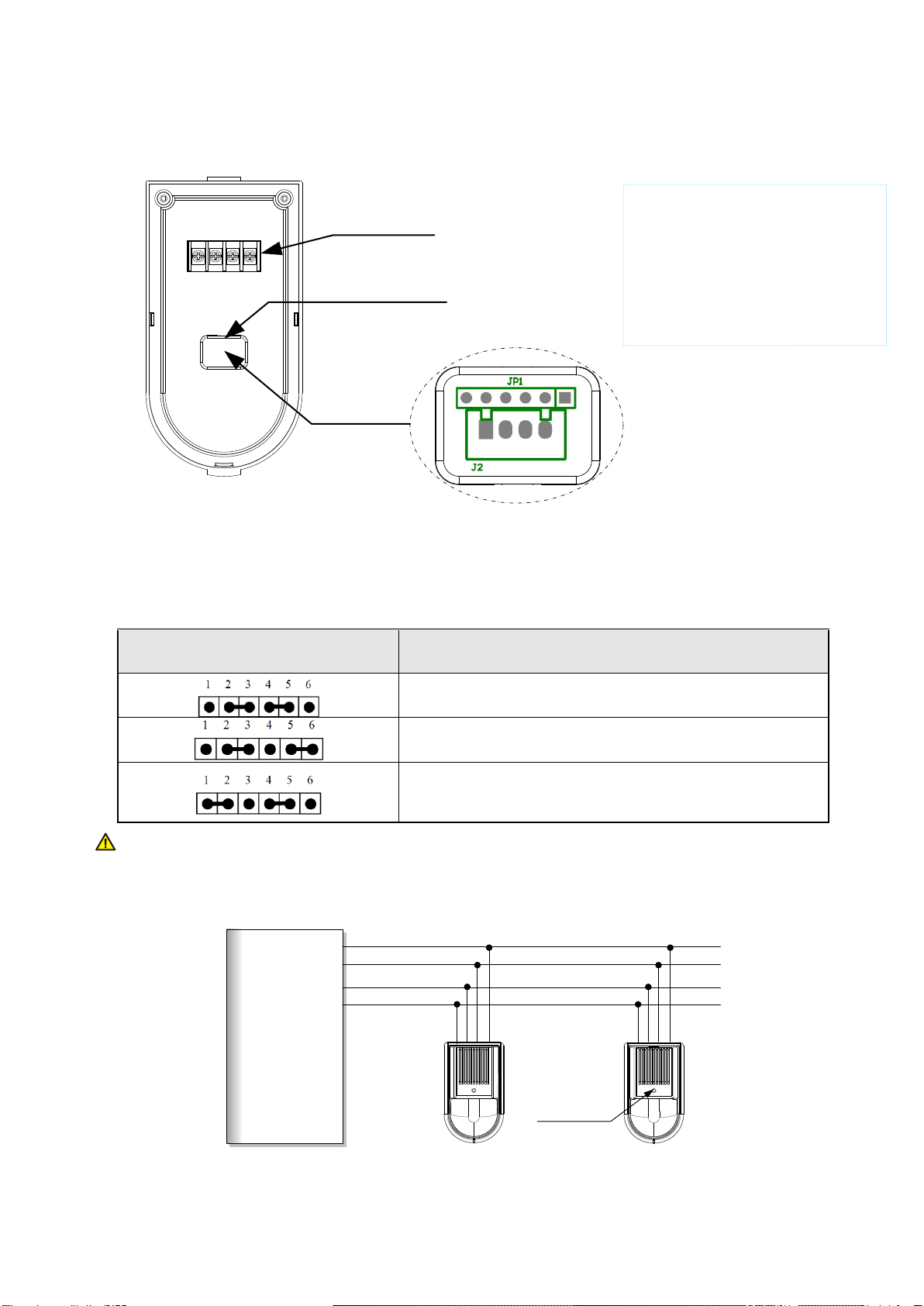
8. Wiring method: Four-wire system, non-polarity two signal buses (L1, L2) and power lines (+24V, GND)
9. Matched host machine: fire alarm control panel (such as ATL-MN300)
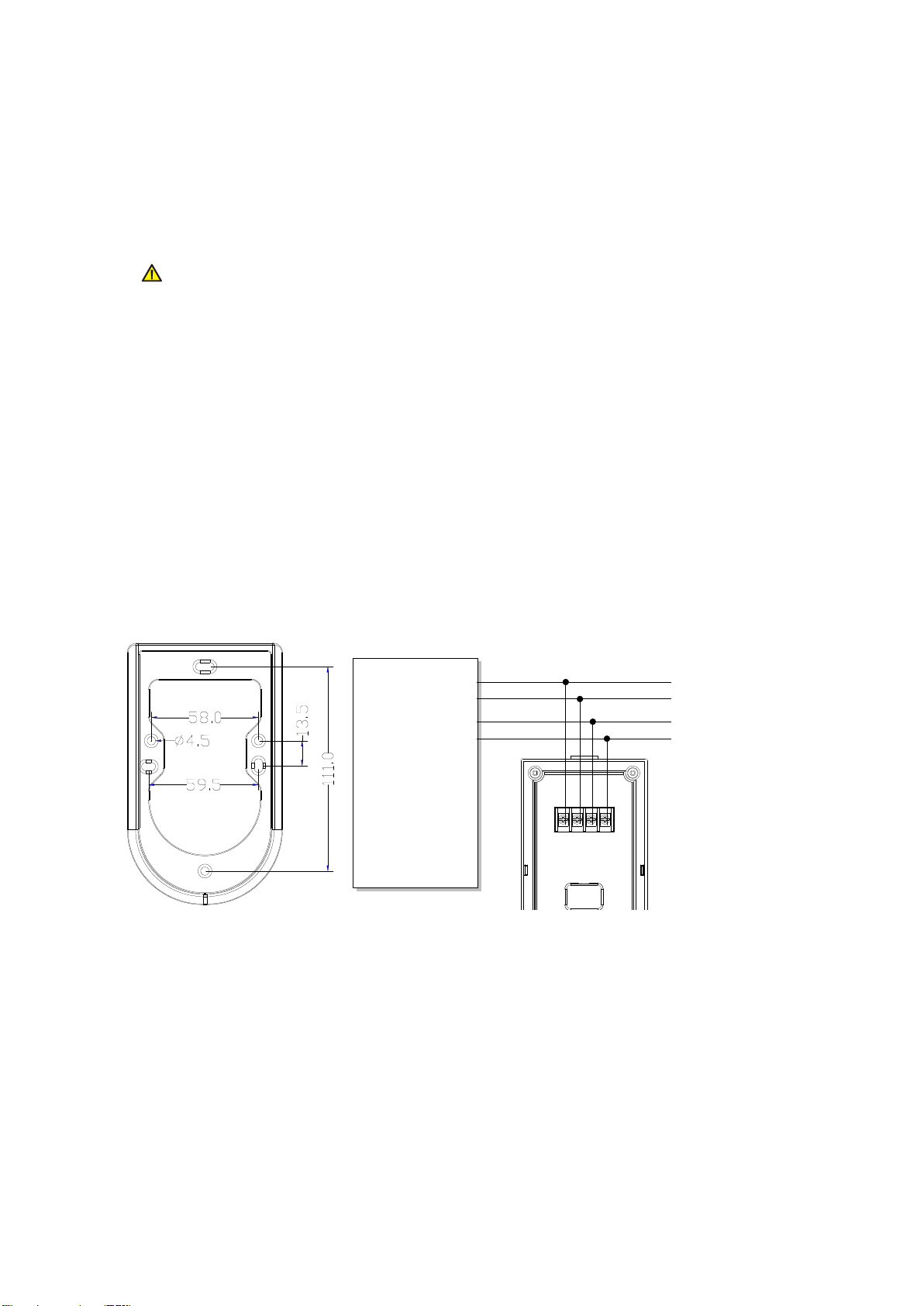
IV. Appearance and dimensions (see Fig.1)
Fig.1

2
V. Use and engineering application
1 Fig.2 is the schematic diagram of the rear cover of the horn/strobe.
Connecting Terminal
Debugging Port
Enlarged
Drawing JP1: Setup of selection between
audible alarm and flashing alarm
J2: Address coding socket
1 6
1 2 3 4
Fig.2
2. Selection between audible alarm and flashing alarm: Select through the jumper (JP1) below the
debugging port lid on the back of the horn/strobe, following the instructions of the jumper.
Jumper setup
Function
Audible alarm and flashing alarm (factory default)
Flashing alarm (no audible alarms will be given)
Audible alarm (no flashing alarms will be given)
Warning: The output mode of a horn/strobe can be one of the three options in the table
above only.
3. Fig.3 shows the general functions and wiring diagram of the product.
Fire Alarm Control
Panel
+24V
GND
L1
L2
Status indicator
Fig.3
SS
Definitions of terminals:
1---+24 power input terminal
2---GND power ground
3---Bus input terminal L1
4---Bus input terminal L2

3
4. Address coding: When a horn/strobe is coded, it is unnecessary to disassemble the wire connecting it
with the host machine; online coding may be done. The specific method is as follows: Open the cover
of the coding setup window, insert the output plug (a four-pin connector) of the coder into the address
coding socket (the socket J2 in Fig.2) of the horn/strobe, set the coder with the coding function,
compile the correct address code and press the RUN key to complete the address coding. (Note: See
the User’s Manual of the coder for detailed operation information.)
Warning: It is necessary to have “online coding” done when the system is powered off
or related equipment may be damaged.
5. Usage: Do not connect the power supply until the address of the horn/strobe has been set and
confirmed and the fire alarm control panel has been properly connected. After the fire alarm control
panel is successfully reset, the red status indicator (see Fig.3 for its location) of the horn/strobe will
blink. After the horn/strobe receives an operation signal, the status indicator will remain lit and the
horn/strobe will give both horn/strobe alarm signals.After the system is muted or reset, the horn/strobe
will stop outputting horn/strobe alarm signals and the status indicator will start to blink again.
VI. Installation and debugging
A special base is necessary during the installation of a horn/strobe. As shown in Fig.4, the external
dimensions of the special base are 142×84×10mm (L×B×H). The horn/strobe is subject to a four-wire
non-polarity connection: Terminals 1 and 2 are respectively connected with the terminals +24V and GND
of the DC power supply terminals 3 and 4 are respectively connected with the terminals L1 and L2 of the
signal bus of the fire alarm control panel. See Fig.5.
Fire Alarm Control
Panel
+24V
GND
L1
L2
1 2 3 4
Fig.4 Fig.5
Specific installation and debugging methods:
1. Use two M4 screws to fix the matched mounting base on the designated position via the mounting holes
shown in Fig.4 (the installation may be done horizontally or vertically. Choose any two of the six mounting
holes for installation) as instructed in the construction drawing and make sure the matched mounting base
has been firmly installed.
2. Disconnect the power supply of the fire alarm control panel and connect all the bases correctly in the way
shown in Fig.5, which is a construction drawing.
Note: When there are a lot of horns/strobes in a system, it is necessary to consider the loading capacity of
the power supply of the fire alarm control panel. An external DC24V auxiliary power supply might be
necessary at this time. Please follow the construction design drawings.
3. Make sure the type of the horn/strobe matches the type given on the construction drawings. Use a coder to
code the horn/strobe according to the address code marked on the construction drawings.

4
4. After all the horns/strobes are installed and checked, connect the power supply of the fire alarm control
panel and conduct automatic login.
5. After a horn/strobe logs into the fire alarm control panel, the red status indicator of the horn/strobe will blink;
after the horn/strobe receives an operation signal, the red status indicator will remain lit and the horn/strobe
will give both horn/strobe alarm signals. After the system is muted or reset, the horn/strobe will stop
outputting horn/strobe alarm signals and the status indicator will restore to the monitoring status and start to
blink again.
VII. Precautions
1. Pay attention to the marking and polarities of the terminals during installation and wiring.
2. Do not make different products share the same address in a single alarm circuit or the system will fail to operate
normally.
3. Make sure during installation that there are no objects in front of the horn/strobe that block the light given by the
horn/strobe and/or prevent the horn/strobe from sounding.
4. Make the installation comply with related provisions of the Code for Installation and Acceptance of Fire Alarm System
(GB50166-2007).
VIII. Maintenance and inspection
1. As specified in national standard Code for Installation and Acceptance of Fire Alarm System (GB50166-2007), at least
quarterly tests should be done for each horn/strobe.
2. If a horn/strobe fails due to a material defect or a manufacturing process defect under the normal conditions of use in
one year following the date of its delivery, we shall repair or replace it for free. However, the faults of the horn/strobe due
to artificial damages, improper use or unauthorized adjustment, reconstruction or disassembly are not covered in the
guarantee and we shall assume no responsibility for all the consequences thereby caused.
3. We may provide a paid repair service for the products with any faults beyond the guarantee range. If you have such
products needing repair, please contact us. When sending such a product to us for repair, you are expected to provide
some important information about the product, such as the phenomenon and possible cause of the product fault, so that
we can find out the cause of the fault in the shortest time and the information may be used as a reference in our future
product development and improvement.
IX. Fault analysis and troubleshooting
Fault phenomenon
Possible cause
Troubleshooting method
Remarks
The horn/strobe cannot
give a horn/strobe alarm
signal.
The wiring is wrong.
Inspect whether or not the wiring is correct.
The linkage function has
not yet been enabled.
Inspect whether or not the general linkage
indicator is lit.
The short-circuit block is
set wrong.
Inspect whether or not the short-circuit
block is correctly set and whether or not its
contact is good.
The internal circuit is
damaged.
Send the horn/strobe back to the factory for
repair.
Table of contents
Popular Horn manuals by other brands

Vixen Horns
Vixen Horns VXO8210/4124C installation guide

Atlas
Atlas AH94-15-BSG Brochure & specs

Valcom
Valcom PagePac V-5331215A quick start guide

HornBlasters
HornBlasters SHOCKER XL 540 installation manual

Vixen Horns
Vixen Horns VXO8705/3114 installation guide

HornBlasters
HornBlasters OUTLAW 232 installation manual