Cooper Notification AMT-12/24 User manual

P82623 F
Sheet 1 of 6
273 Branchport Avenue
Long Branch, NJ 07740
(800) 631-2148 (USA) Thank you for using our products.
(800) 397-5777 (CANADA)
www.coopernotification.com INSTALLATION INSTRUCTIONS
AMT MULTITONE APPLIANCES
AMT-12/24
Use this product according to this instruction manual. Please keep this instruction manual for future reference.
GENERAL:
AMT Multitone Appliances are UL Listed under Standard 464 for Audible Signal Appliances for Fire Protective Service and for General Signaling Service.
They are also ULC Listed under Standard CAN/ULC-S525-07 for Audible Signal Appliances for Fire Alarm Systems. They are listed for both indoor and
outdoor use with the backboxes specified in these instructions. (See Mounting Options A,B,C,D,E,F,G). Cooper Notification's AMT Appliances are
unique multitone alarm appliances with separate input terminals for each sound. They are the ideal choice for Halon Protection Systems and emergency
signaling systems where distinctive multiple alarm conditions are required. Eight groups of three self-prioritized sound outputs are provided with
separate electrically isolated input terminals for each sound (see Table 2 and 5 for sound selections). Sound output can be field set to provide either
HIGH (HI) dBA or STANDARD (STD) dBA sound output level. AMT Multitone Appliances can be field set for either 12VDC or 24VDC operation and are
designed for use with either filtered or unfiltered Full-Wave-Rectified (FWF) input voltage. All inputs are polarized for compatibility with standard reverse
supervision of circuit wiring by Fire Alarm Control Panel (FACP).
NOTE: All CAUTIONS and WARNINGS are identified by the symbol . All warnings are printed in bold capital letters.
WARNING: PLEASE READ THESE INSTRUCTIONS CAREFULLY BEFORE USING THIS PRODUCT. FAILURE TO COMPLY WITH ANY OF
THE FOLLOWING INSTRUCTIONS, CAUTIONS AND WARNINGS COULD RESULT IN IMPROPER APPLICATION, INSTALLATION AND/OR
OPERATION OF THESE PRODUCTS IN AN EMERGENCY SITUATION, WHICH COULD RESULT IN PROPERTY DAMAGE AND SERIOUS INJURY
OR DEATH TO YOU AND/OR OTHERS.
NOTE: All Canadian installations should be in accordance with the Canadian Standard for the Installation of Fire Alarm Systems, CAN/ULC-S524 and
the Canadian Electrical Code, Part 1. Final acceptance is subject to authorities having jurisdiction.
WARNING: THE AMT MULTITONE APPLIANCES MUST BE FIELD SET TO THE DESIRED INPUT VOLTAGE, dBA SOUND OUTPUT LEVEL
AND ALARM TONE BEFORE THEY ARE INSTALLED. THIS IS DONE BY PROPERLY INSERTING A JUMPER PLUG AND ADJUSTING A FOUR
POSITION SWITCH IN ACCORDANCE WITH THESE INSTRUCTIONS. INCORRECT SETTINGS WILL RESULT IN IMPROPER PERFORMANCE
AND MAY DAMAGE THE PRODUCT, WHICH COULD RESULT IN PROPERTY DAMAGE AND SERIOUS INJURY OR DEATH TO YOU AND/OR
OTHERS.
SPECIFICATIONS:
Table 1: dBA Ratings for AMT Multitone Signal
Typical Anechoic
dBA at 10 Feet per
CAN/ULC S525-07 Rated Reverberant dBA
At 10 Feet Per UL 464
Tone At Nominal At Minimum At Nominal
Input Voltage Input Voltage Input Voltage
HI STD HI STD HI STD
Horn 99 93 88 79 88 82
Bell 93 88 82 75 85 79
March Time Horn 98 92 85 79 88 82
Code-3 Horn * (ANSI S3.41 Temporal Pattern) 99 93 85 75 85 79
Code-3 Tone * (ANSI S3.41 Temporal Pattern) 95 89 85 79 88 82
Slow Whoop 99 94 82 75 85 79
Siren 97 92 82 75 82 75
HI/LO 93 85 82 75 85 79
Vibrating Chimes 89 83 79 73 82 75
* - For ULC applications, only Code 3 Horn and Code 3 Tone are required to meet the ULC minimum of 85 dBA and the audible signal temporal
pattern mandated by the National Building Code of Canada.
Copyright 2015 Cooper Wheelock Inc., dba Cooper Notification. All rights reserved.

P82623 F
Sheet 2 of 6
Table 2: Current Ratings for AMT Multitone Audible Appliances
Tone
Tone Maximum RMS Current
(AMPS)
Description 24VDC 24VRMS 12VDC 12VRMS
HI STD HI STD HI STD HI STD
Horn Broadband Horn (Continuous) 0.108 0.043 0.092 0.050 0.210 0.058 0.230 0.103
Bell 1560 Hz Modulated (0.07 Sec. ON/Repeat) 0.057 0.026 0.040 0.028 0.117 0.031 0.150 0.057
March Time Horn Horn (0.25 Sec. ON/0.25 Sec. OFF/Repeat) 0.108 0.035 0.092 0.050 0.210 0.059 0.229 0.091
Code 3 Horn Horn (ANSI S3.41 Temporal Pattern) 0.108 0.043 0.092 0.050 0.210 0.057 0.241 0.093
Code 3 Tone 500 Hz (ANSI S3.41 Temporal Pattern) 0.060 0.030 0.051 0.031 0.168 0.052 0.216 0.100
Slow Whoop 500-1200Hz Sweep (4.0 Sec. ON/0.5 Sec. OFF/Repeat) 0.112 0.044 0.092 0.050 0.182 0.056 0.212 0.110
Siren 600-1200Hz Sweep (1.0 Sec. ON/Repeat) 0.102 0.038 0.078 0.043 0.177 0.055 0.197 0.107
HI/LO 1000/800 Hz (0.25 Sec. ON/Alternate) 0.064 0.030 0.049 0.034 0.131 0.028 0.186 0.088
Vibrating Chime 700Hz (1.0 Sec. Decay/Repeat) 0.041 0.020 0.044 0.029 0.090 0.028 0.108 0.042
Table 3: ULC Directional Characteristics
24VDC Horizontal -3dBA: 35 degrees left, 35 degrees right
-6dBA: 55 degrees left, 55 degrees right
Vertical -3dBA: 35 degrees upward, 35 degrees downward
-6dBA: 65 degrees upward, 55 degrees downward
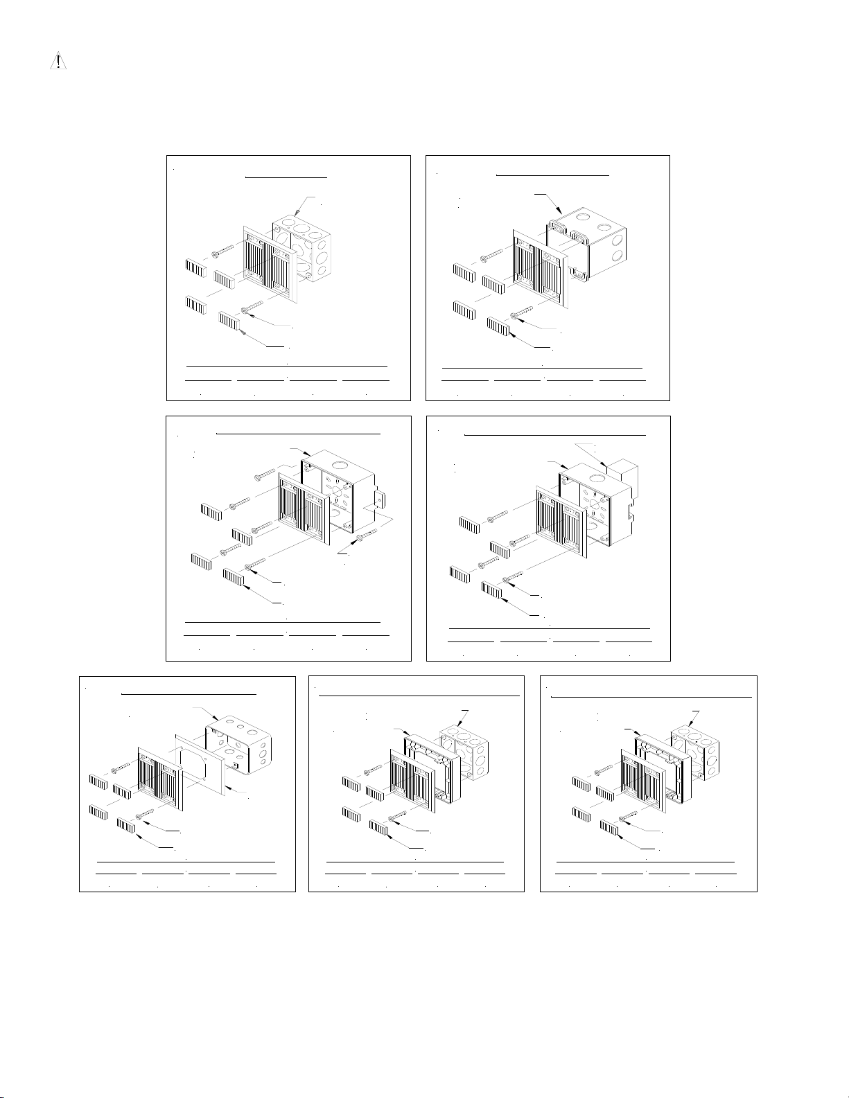
WARNING: CHECK THE MINIMUM AND MAXIMUM OUTPUT OF THE POWER SUPPLY AND STANDBY BATTERY AND SUBSTRACT THE
VOLTAGE DROP FROM THE CIRCUIT WIRING RESISTANCE TO DETERMINE THE APPLIED VOLTAGE TO THE SIGNALING APPLIANCE.
WARNING: FOR UL/ULC APPLIANCES THESE APPLIANCES WERE TESTED TO THE OPERATING VOLTAGE LIMITS OF 16-33 VOLTS FOR
24V APPLICATIONS AND 8.0-17.5 VOLTS FOR 12V APPLICATIONS USING FILTERED (DC) OR UNFILTERED FULL-WAVE-RECTIFIED (FWR).
DO NOT APPLY 80% AND 110% OF THESE VOLTAGE VALUES FOR SYSTEM OEPRATION.
WARNING: MAKE SURE THAT THE TOTAL RMS CURRENT REQUIRED BY ALL APPLIANCES THAT ARE CONNECTED TO THE SYSTEM’S
PRIMARY AND SECONDARY POWER SOURCES, NAC CIRCUITS, OR WHEELOCK’S POWER SUPPLIES DO NOT EXCEED THE POWER
SOURCES’ RATED CAPACITY OR THE CURRENT RATINGS OF ANY FUSES ON THE CIRCUITS TO WHICH THESE APPLIANCES ARE WIRED.
OVERLOADING POWER SOURCES OR EXCEEDING FUSE RATINGS COULD RESULT IN LOSS OF POWER AND FAILURE TO ALERT
OCCUPANTS DURING AN EMERGENCY, WHICH COULD RESULT IN PROPERTY DAMAGE AND SERIOUS INJURY OR DEATH TO YOU AND/OR
OTHERS.
When calculating the total currents: Use Table 2 to determine the highest value of “RMS Current” for an individual AMT (across the expected operating
voltage range of the AMT’s), then multiply these values by the total number of AMT’s; be sure to add the currents for any other appliances powered by
the same source and include any required safety factors.
If the peak current exceeds the power supplies’ peak capacity, the output voltage provided by the power supplies may drop below the listed voltage
range of the appliances connected to the supply and the voltage may not recover in some types of power supplies. For example, an auxiliary power
supply that lacks filtering at its output stage (either via lack of capacitance and/or lack of battery backup across the output) may exhibit this characteristic.
The AMT Multitone audible appliances produce a brief inrush current that lasts for just 2 microseconds but can reach a peak value of 8.0 Amps (11.2
amps for FWR input).
AMT MULTITONE SETTINGS:
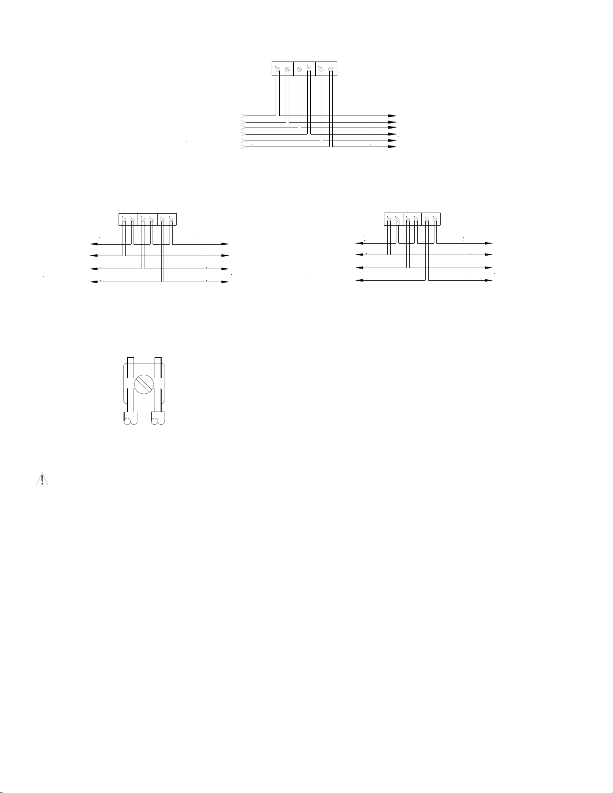
The Jumper Plug (DP1) and Switch (SW1) of the AMT Multitone Appliances, shown in Figure 1, are used to set the input voltage dBA sound output level
and alarm tone. The factory settings are shown below. Read these instructions carefully before changing any of these factory settings.
Figure 1:
PC Board Layout Showing Location
of Jumper Plug (DP1) and Switch (SW1)
+PRI 1-
12
4
3
2
1
24
SW1
ON
+PRI 2- +PRI 3-
12
4
3
2
1
24
SW1
ON
SLIDE HERE FOR (0)
SLIDE HERE FOR (1)
The Factory Settings are:
24VDC: DP1 SET ON 24
HIGH dBA: SW1 POS 1 = 1
Priority 1 (PRI 1) HORN TONE:
Priority 2 (PRI 2) BELL TONE:
Priority 3 (PRI 3) SIREN TONE:
}SW1 POS 2, 3, 4 = 1, 1, 1

P82623 F
Sheet 3 of 6
STEP 1:
Set desired input voltage and dBA sound output level as follows (Refer to Figures 2 and 3):
AMT Multitone Appliances are field set for input voltage and dBA sound output level by inserting a Jumper Plug (DP1) and adjusting a four position
Switch (SW1) as shown in Table 4 and Figures 2 and 3. Use DP1 to select the desired voltage and SW1 Position 1 to select the dBA sound output level.
Table 4: Input Voltage and dBA Sound Output Level Settings
Input Voltage and Decibel Level DP1 and SW1 Settings
24 VDC/HIGH dBA: Set DP1 on 24; set SW1 POS 1 on 1 (Factory Setting)
24 VDC/STD dBA: Set DP1 on 24; set SW1 POS 1 on 0
12 VDC/HIGH dBA: Set DP1 on 12; set SW1 POS 1 on 1
12 VDC/STD dBA: Set DP1 on 24; set SW1 POS 1 on 1
Figure 2: Figure 3:
Jumper Plug (DP1) Settings
JUMPER PLUG
SHOWNSET ON 24
SHOWNSETON12
12
24
(Use Needle Nose Pliers to Lift and Properly Insert the Jumper Plug)
Switch (SW1) Settings
POS 1
POS2
POS3
POS4
SLIDE HERE FOR (1)
SLIDE HERE FOR (0)
USEASMALLSCREWDRIVERTO
CHANGETHE SWITCHPOSITION.
WARNING: DO NOT APPLY 24VDC INPUT IF THE JUMPER PLUG (DP1) IS SET ON 12. THIS CAN DAMAGE THE UNIT. DOUBLE CHECK
THE JUMPER PLUG (DP1) AND SWITCH (SW1) SETTINGS TO MAKE SURE THEY ARE CORRECT. IMPROPER SETTINGS CAN DAMAGE THE
UNIT OR RESULT IN NO SOUND OUTPUT OR A dBA SOUND OUTPUT LEVEL THAT IS BELOW THE MINIMUM CODE REQUIREMENTS FOR
PUBLIC MODE FIRE PROTECTION, WHICH COULD RESULT IN PROPERTY DAMAGE AND SERIOUS INJURY OR DEATH TO YOU AND/OR
OTHERS.
STEP 2:
Set desired alarm tone as follows (refer to Figure 3 and Table 5).
AMT Multitone Appliances are field set for any one of eight groups of self-prioritized tones by setting a four-position switch (SW1) as shown in Figure 3
and Table 4. Use SW1 POS 2, 3, 4 to select the desired alarm tone (refer to Table 5 below).
Table 5: Alarm Tones
Tones Switch Settings
PRI 1 PRI 2 PRI 3 POS 2 POS 3 POS 4
Horn Bell Siren 1 1 1
Code 3 Horn Siren Vibrating Chime 1 0 1
Slow Whoop March Time Horn HI/LO 0 0 1
March Time Horn HI/LO Vibrating Chime 1 1 0
Code 3 Horn Bell Siren 0 1 1
Siren Horn Vibrating Chime 0 1 0
Bell March Time Horn Siren 1 0 0
Code 3 Tone HI/LO Siren 0 0 0
NOTE: The prioritized tones contained in each group is factory pre-set which can not be changed.
NOTE The Code 3 Horn and Code 3 Tone (set on HIGH dBA) incorporate the temporal pattern specified by ANSI/NFPA for standard emergency
evacuation signaling. They should be used only for fire evacuation signaling and not for any other purpose.
The Horn and Bell Tones can be used on coded systems with a minimum On-Time of 1/4 second if the audible and strobe are wired to operate
independently. All other tones are recommended for use only on continuous (non-coded) systems.
WARNING: THE AMT APPLIANCE IS A “FIRE ALARM DEVICE – DO NOT PAINT”.
WIRING DIAGRAMS:

P82623 F
Sheet 4 of 6
Supervised System
(+) (-)
TONEXTAPPLIANCE
OR END OF LINE
RESISTOR(EOLR)
FROMPRECEDING
APPLIANCEOR
FIRE ALARM CONTROL
PANEL(FACP)
PRI 1 PRI 2
(-)
(+)
PRI 3
(-)
(+)
PRI 1
PRI 2
PRI 3 PRI 3
PRI 2
PRI 1
Isolated inputs are provided for independent supervision and actuation of the three audible inputs.
Unsupervised System
Common Positive Unsupervised System
Common Negative
(+) (-)
PRI 1 PRI 2
(-)(+)
PRI 3
(-)(+)
PRI 1
PRI 2
PRI 3 PRI 3
PRI 2
PRI 1
POSITIVE
COMMON
COMMON
POSITIVE
FROMPRECEDING
APPLIANCE OR
FIREALARM CONTROL
PANEL(FACP)
TO NEXT APPLIANCE
OR END OF LINE
RESISTOR (EOLR)
(+) (-)
PRI 1 PRI 2
(-)(+)
PRI 3
(-)(+)
PRI 1
PRI 2
PRI 3 PRI 3
PRI 2
PRI 1
NEGATIVE
COMMON
COMMON
NEGATIVE
FROMPRECEDING
APPLIANCEOR
FIREALARMCONTROL
PANEL (FACP)
TONEXTAPPLIANCE
OR END OF LINE
RESISTOR (EOLR)
For applications not requiring supervision: connect all positive (+)
terminals to the power source. The negative (-) terminal for each
appliance will actuate the appliance.
For applications not requiring supervision: connect all negative (-)
terminals to the power source. The positive (+) terminal for each appliance
will actuate the appliance.
In case of simultaneous inputs, the three audible outputs are self-prioritized as follows: 1st priortiy= PRI 1; 2nd priority = PRI 2; 3rd priority = PRI 3.
Leave any unused inputs disconnected.
1. AMT Multitone appliance models have in-out wiring terminals that
accept two #12 to #18 American Wire Gauge (AWG) wires at each
screw terminal. Strip leads 3/8 inches and connect to screw
terminals.
2. Break all in-out wire runs on supervised circuits to assure integrity of
circuit supervision as shown on left. The polarity shown in the
wiring diagrams is for operation of the appliances. The polarity is
reversed by the FACP during supervision.
NOTE: Wiring method shall be in accordance with CSA C22.1, Canadian Electrical Code, Part 1, Safety Standard for Electrical Installations, Section 32.
MOUNTING PROCEDURES:
CAUTION: If sheated multiconductor cable or 3/4" conduit fittings are used, check that installed product has sufficient clearance and wiring room
prior to installing backboxes and conduit.
1. AMT Multitone Appliances can be flush mounted to a standard 4 inch square by 2-1/8 inch deep electrical box (Figure A) or a standard 2-gang by 2-
1/2 inch minimum deep electrical box (Figure B).
2. Select largest backbox shown in Mounting Options where possible, to provide additional wiring room for easy installation.
3. Conduit entrance to backboxes should be selected to insure sufficient wiring clearance for installed equipment. When extension rings are required,
conduit should enter through backbox, not extension ring. Use Steel City #53151/1-1/2" deep or #53171/2-1/8" deep extension rings or equal with
same area cut out in back.
4. The AMT-12/24 model can also be surface mounted to Cooper Notification's Indoor/Outdoor Backbox (Model IOB) for indoor/outdoor use (Figure C).
5. The AMT-12/24 model is supplied with four snap-in covers to hide the mounting holes and provide an attractive installation. The snap-in covers are
interchangeable and have slots on each end so they can be removed if necessary (by prying them up with a thin blade screwdriver). To insert snap-
in cover, slide one side partially into mounting hole recess; align the cover so that snap-in cover and grille are parallel to each other (not tilted) and
snap cover into place.
6. The IOB surface backbox has 1/2 inch conduit knockouts on two sides. It has a variety of knockouts on the back for mounting it to recessed
electrical boxes and for wire entrances (Figure D). It can also be mounted to a surface with the two mounting ears that are supplied. The ears slide
into slots on the back of the box. Use appropriate anchors for the wood screws that are supplied with the box (if necessary).
7. For outdoor use, the IOB includes a prefastened gasket and four hole plugs. Use the mounting ears to secure the box (do not use the back
knockouts). Use the hole plugs to seal the unused mounting holes on the AMT Multitone grille (press them in securely from the back side of the
grille). Mount the unit to the IOB with the four #8-18 screws supplied with the box.
8. All models are UL Listed for indoor and outdoor use with a temperature range of -40oF to +150oF (-40oC to +66oC) and maximum humidity of 98%
2% RH.
MOUNTING OPTIONS:

P82623 F
Sheet 5 of 6
CAUTION: The following figures show the maximum number of field wires (conductors) that can enter the backbox used with each mounting option.
If these limits are exceeded, there may be insufficient space in the backbox to accommodate the field wires and stresses from the wires could damage
the product.
Although the limits shown for each mounting option comply with the National Electrical Code (NEC), Cooper Notification recommends use of the largest
backbox option shown and the use of approved stranded field wires, whenever possible, to provide additional wiring room for easy installation and
minimum stress on the product from wiring.
FLUSH (4" BOX)
A
10 48
8
AWG #18 AWG#16 AWG #14 AWG #12
MAXIMUM NUMBER OF CONDUCTORS
SCREW COVERS
#8-32 SCREWS
4" SQ. X 2-1/8"
DEEPBACKBOX
B
FLUSH(2-GANGBOX)
2-GANG x 2-1/2"
DEEPBACKBOX
AWG #18 AWG#16 AWG #14 AWG #12
10 8 8 4
MAXIMUM NUMBER OFCONDUCTORS
#6-32 SCREWS
SCREWCOVERS
C
SURFACE (INDOOR/OUTDOOR)
#8-18 SCREWS
INDOOR/OUTDOOR
WOOD
SCREWS
SCREWCOVERS
12 121212
AWG #18 AWG #16 AWG #14 AWG #12
MAXIMUM NUMBER OF CONDUCTORS
BACKBOXIOB
D
CONCEALED CONDUIT MOUNTING
EXISTING
BOX
#8-18 SCREWS
INDOOR/OUTDOOR
SCREWCOVERS
12 121212
AWG #18 AWG#16 AWG#14 AWG#12
MAXIMUM NUMBER OF CONDUCTORS
BACKBOX IOB
EXISTINGFSB
BOX
RETROFIT PLATEMOUNTING
E
12 1212
12
AWG#18 AWG#16 AWG#14 AWG #12
MAXIMUM NUMBER OF CONDUCTORS
SCREWCOVERS
#8-32 SCREWS
RETROFIT
PLATE
DBB OR 4" SQ. X 2-1/8"
DEEPBACKBOX
ISP EXTENDER
SURFACEOR SEMI-FLUSH (4" X 2-1/8" BOX)
F
12 810
12
AWG#18 AWG#16 AWG#14 AWG #12
MAXIMUM NUMBER OF CONDUCTORS
SCREWCOVERS
#8-32 SCREWS
SURFACEOR SEMI-FLUSH (4" X 1-1/2" BOX)
G
#8-32 SCREWS
SCREWCOVERS
MAXIMUM NUMBER OF CONDUCTORS
AWG #18 AWG#16 AWG#14 AWG#12
8 8 410
ISP EXTENDER
DEEP BACKBOX
DBB OR 4" SQ. X 2-1/8"
AMT Appliances can be wall or ceiling mounted.

P82623 F
Sheet 6 of 6
WARNING: IF AMT MULTITONE APPLIANCES ARE OPERATED WITHIN 15 INCHES OF A PERSON'S EAR, THEY CAN PRODUCE A SOUND
PRESSURE LEVEL THAT EXCEEDS THE MAXIMUM 120 dBA PERMITTED BY ADA AND OSHA RULES. EXPOSURE TO SUCH SOUND LEVELS
CAN RESULT IN DAMAGE TO A PERSON'S HEARING.
WARNING: NFPA CODES REQUIRE SIGNALING APPLIANCES TO BE SUPERVISED. CHECK TO BE CERTAIN THAT UNSUPERVISED
SIGNALING APPLIANCES DO NOT VIOLATE ANY APPLICABLE CODES.
CAUTION: Check the installation instructions of the manufacturers of other equipment used in the system for any guidelines or restrictions on wiring
and/or locating Notification Appliance Circuits (NAC) and notification appliances. Some system communication circuits and/or audio circuits, for
example, may require special precautions to assure electrical noise immunity (e.g. audio crosstalk).
NOTE: This equipment has been tested and found to comply with the limits for a Class B digital device, pursuant to Part 15 of the FCC Rules. These
limits are designed to provide reasonable protection against harmful interference in residential installation. This equipment generates, uses and can
radiate radio frequency energy and, if not installed and used in accordance with the instructions, may cause harmful interference to radio
communications. However, there is no guarantee that interference will not occur in a particular installation. If this equipment does cause harmful
interference to radio or television reception, which can be determined by turning the equipment off and on, the user is encouraged to try to correct the
interference by one or more of the following measures: 1) Reorient or relocate the receiving antenna, 2) Increase the separation between the equipment
and receiver, 3) Connect the equipment into an outlet on a circuit different from that to which the receiver is connected, and 4) Consult the dealer or an
experienced radio/TV technician for help.
This Class B digital apparatus meets all requirements of the Canadian Interference-Causing Equipment Regulations.
Cet appareil numérique de la classe B respecte toutes les exigences du Règlement sur le matériel brouilleur du Canada.
The AMT Multitone products and these instructions are copyrighted by Cooper Notification and contain proprietary, confidential and trade secrets of
Cooper Notification. No part of the AMT Multitone products and these instructions may be photocopied, printed or reproduced in any form or modified,
adapted, changed or enhanced, or converted to another programming language, or used to create updated, related or derivative works, without the prior
written consent of Cooper Notification. No part of the AMT Multitone shall be decompiled, disassembled or reverse engineered.
ANY MATERIAL EXTRAPOLATED FROM THIS DOCUMENT OR FROM COOPER NOTIFICATION MANUALS OR OTHER DOCUMENTS
DESCRIBING THE PRODUCT FOR USE IN PROMOTIONAL OR ADVERTISING CLAIMS, OR FOR ANY OTHER USE, INCLUDING DESCRIPTION
OF THE PRODUCT'S APPLICATION, OPERATION, INSTALLATION AND TESTING IS USED AT THE SOLE RISK OF THE USER AND COOPER
NOTIFICATION WILL NOT HAVE ANY LIABILITY FOR SUCH USE.
01/16
Table of contents
Other Cooper Notification Horn manuals
Popular Horn manuals by other brands

Vixen Horns
Vixen Horns VXH4124C installation guide

Viking
Viking 300AE product manual

Valcom
Valcom VIP-148AL-IC manual

Vixen Horns
Vixen Horns VXH3418C installation guide

Federal Signal Corporation
Federal Signal Corporation Vibratone 350WBX installation manual

Vixen Horns
Vixen Horns VXH1264YB installation guide

Edwards Signaling
Edwards Signaling 5522M Installation sheet

Vixen Horns
Vixen Horns VXO8530/3311C installation guide

Bosch
Bosch LBC 3428 installation manual

Radio Shack
Radio Shack 320-2037 manual

Vixen Horns
Vixen Horns VXH6801R installation guide

Behringer
Behringer Eurosound Megaphone XT quick start guide