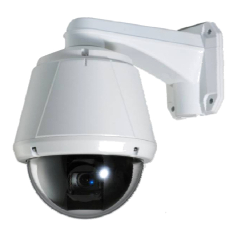
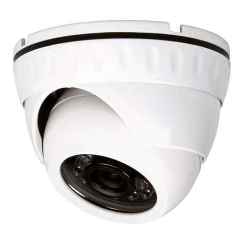
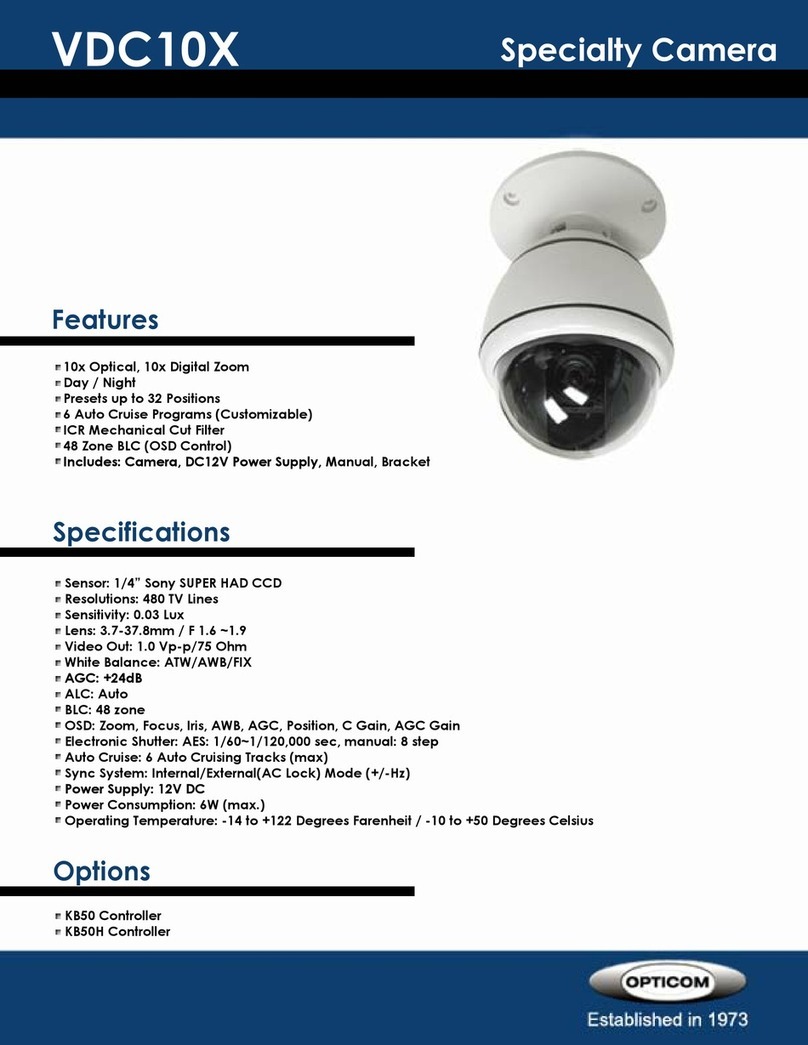
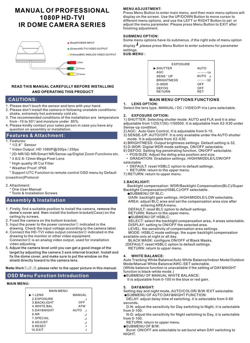
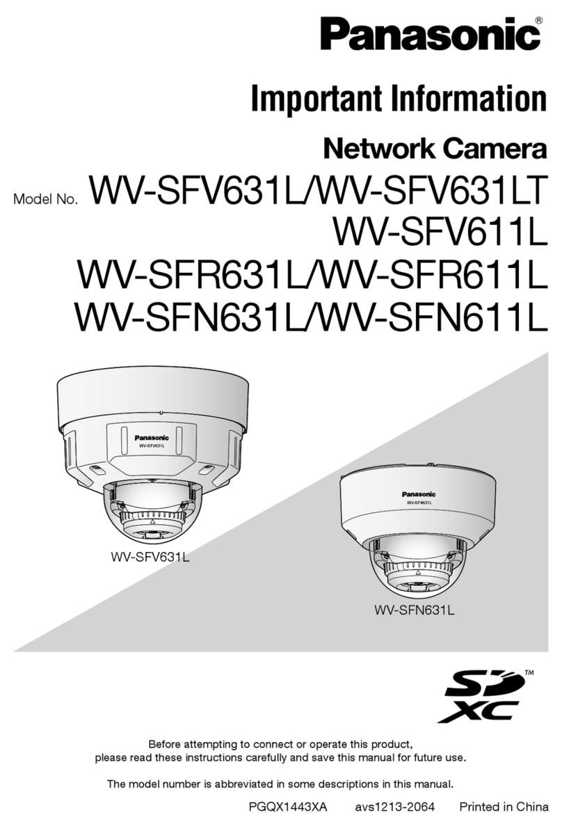
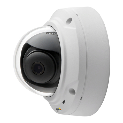
Atronix ATX 3010 Assembly instructions

Integrated Mini High Speed Dome
MODEL ATX 3010 ( Sony ) and ATX 3011 ( Samsung )
Installation& Programming Manual

Sumary
Chapter 1 Installation manual
………………………………………… ………………………………1
1 Forward…………………………………………………………………………………………………… 1
2 Safeguards and warnings………………………………………………………………… ………..….1
3 installation warning…………………………………………………… ………………………………..1
4 Main function features……………………………………………………………………………..…... 4
5 Outdoor pendant intallation …………………………………………………….…………….… 5
6 Indoor pendant Installation………………………………………………………………………….… 8
7 Indoor surface-mount installation………………………………..………………...……….…….... 11
8 Technology specification……………………………………………………………..……….......… 13
Chapter 2 Operation…………………………………………………………………..……………..….. 16
1 Basic operation explanation……………………………………………………………….…...….…16
2 PTZ functions
………………………………………………………………………………..…….... 19
3 Function explanation ………………………………………………………………………...…….… 19
4 Menu explanation………………………………………………………………………………….…... 20
5 Camera menu …………………………………………………………………………..…………..….. 21
6 Dome camera switch setting…………………………………………………………………..…..… 27
Appendix..…………………………………………………………………………………………..…..… 31
1 P protocol……………………………………………………………………………………….........… 31
2 D protocol…………………………………………………………………………………………......... 31
Appendix Troubleshooting ……………………………………………………………...…………... 34
1 About image………………………………………………………………………………………......… 34
2 About control…………………………………………………………………………………...……..... 34
3 About installation…………………………………………………..…………………………….......... 35

1
Chapter 1: INSTALLATION MANUAL
1 FORWARD
This manual introduces the function, installation and operation of the integrated speed dome
camera in details. Please thoroughly familiarize yourself with the information in this manual prior to
installation.
This series dome cameras are equipped with DSP integrated camera, in-built zoom lens and
decoder controller.
Protocol P/D is used in this series dome cameras. It can support most popular system platforms,
such as: PELCO. This manual will not explain the operation of other system if connecting with other
system, please contact with the system manufacture or dealer.
2 SAFEGUARD AND WARNING
Prior to installation and use of this product, the following WARNING should be observed. This
product can be only used in specified range in order to avoid any damage or danger.
Installation and servicing should only be done by qualified service personnel;
It must not be installed where exposed to rain and moisture and it can not be used in
unqualified temperature, humidity and power supply.
Only use replacement parts recommended by us.
After replacement/repair of this unit’s electrical components, conduct a resistance
measurement to avoid short circuit or turnoff.
Please use the soft cloth to clean the dome. Use neuter cleanser if bad smeared. No use the
strong or corrosive cleanser avoiding scuffing.
Be cautious of moving, never press the drive parts heavily avoiding dome troubles.
The installation materials should be capable of supporting four times the weight of the
enclosure, pan/tilt, camera and lens combination.
Please thoroughly read this manual prior to installation and operation.
3 INSTALLATION WARNING
(1) Please thoroughly read this manual prior to installation.
(2) Use the kind power and voltage that marked on the power supply wire. Standard voltage is
AC24V, best power supply is AC24V±10%. Higher or lower voltage for long period would cause
troubles. Keep the power over 60W, otherwise there would be abnormal situation for control.

2
(3) Don’t make the camera face the strong light object for long time, or the CCD would lose
effectiveness, and cause the results of image losing or image distortion.
(4) There are features of water proof and aquosity proof for this series camera. Meet the IP66
standard. If the wires are not lay out correctly, the rain would goes into the dome drive along with
the wires. This will cause short circuit problem and more serious result to the damage of camera.
The correct and wrong installation as following:
It must follow the manual to connect correctly the power supply cable, video cable, control cable
and soon, look at the picture:
Attention:
A Cover the end of BNC with rubber cover when finish connecting the BNC wire, for keeping it away
from other metal.
B 485+, 485- are the anode and cathode of RS485, please connect them according to the diagram,
otherwise the dome drive can not be controlled.
C It will be better if can connect the EARTH wiring. By connecting to the earth, the RS485 and video
port can pass 10/700us 1500V differential-mode and 4000V common-mode lightning strike and
surge testing. Which reach ITU-
--
-T
K21-
--
-2003 international lightning proof standard and GB9043
standard. But it can’t prevent direct lightning stroke, will need additional device.

3
Requirements for the connect cables
A. Requirements for the 24VAC power supply cable
Normally, the power wires have some resistance. There is some loss during voltage transmission.
The longer the wire is and the smaller the wire diameter is, the worse loss will be. Please refer to
following wire diameter and distance requirement in order to avoiding the abnormal work caused by
insufficient voltage.
Power supply cable
diameter
0.5mm²(20#)
1.0mm
²(18#)
1.5mm
²(16#)
2.5mm²(14#)
Dome camera distance 11m(37ft) 18m(60ft) 29m(95ft) 46m(152ft)
B. Requirements for the video cable
The video wire also has inner loss as the power wire. The more the wire is and the small the
specification is, the worse loss it will be. The high the signal frequency is, the obvious the loss is.
The normal video wires models and the MAX. Transmission distance is listed in following table:
Video cable model Max. transmitiion
distance
Video cable model Max. transmittion
distance
75-2 About 150m 75-5 About 370m
75-3 About 200m 75-7 About 500m
75-4 About 270m
75-9 About 680m
C. Requirements for RS485 control cable
RS485 cable transmittion distance is relative to the cable diameter, transmittion rate and
electro-magnetic interference condition. For exampls: with a 1.0mm² twisted pari, if under 9600b/s
transmittion rate, the longest transmittion distance is 800M; if under 4800b/s transmittion rate, the
longest transmittion distance is 1000M; and if under 2400b/s transmittion rate, the longest
transmittion distance is 1200M.
Sometimes the installer use star connection mode, which doesn’t meet the industry standard for
RS485 requirement. If the devices distance is far, it may cause signal reflect, reduce
Anti-interference capability,and the camera will lose normal control. The suggestion is to parallel
connect a 120 ohm resistance at the fastest RS485 anode and cathode; or adopt RS485 distributor.
Wire RS485 common trouble and solution
Trouble
phenomena
Reason Solution
Camera can
configure but
A. The baud rate of dome and
host is not accordant
A、
、、
、make baud rate of dome and
host accordant.

4
can’t be
controlled
B. The anode and cathode of
RS485 are connected wrong
C. wire connection is loose
D. wire RS485 break off or
short circuit
B、
、、
、adjust the +、-
+、-+、-
+、-
poles of
wire RS485
C、
、、
、fasten the connection
D、
、、
、replace the wire RS485
Camera can be
controlled but
not moved
smoothly
A、
、、
、Wire RS485 connection is
unstable
B、
、、
、One of RS485 wires is
break off
C、
、、
、The distance between host
and camera is too far
D、
、、
、parallel connection of
cameras is overfull
A、
、、
、Reconnect the wire RS485
B、
、、
、Replace wire RS485
C、
、、
、install the terminal matched
resistance
D、
、、
、install RS485 divider.
4 MAIN FUNCTION FEATURES
Aluminum-alloy enclosure dome;
Accurate motor driving stable operation , without dithering and noise, little heat release
Indoor/outdoor pendant installation
Support preset, Auto scan and preset tour.
High reliability, internal data never lost when power is off
RS-485 feed back the orientation of the pan& tilt, target angle preset control
Baud rate: 1200, 2400, 4800, 9600bps are available
Pan & tilt orientation display, camera zoom display
Built-in function menu, the function of camera and pan/tilt can be set.
Powering on self-restoring style—users can assign the movement after powering on. For
example: set for resume
Multi- automatic scan mode, the auto- scan speed can be set by build-in menu
Functions of video freeze and backlight compensation
Day & night camera can be set into single color or single black mode according to the
circumstance
Change speed proportionally--Pan/tilt speed and the depth of zoom lens decline proportionally
Pattern track memory function, can record the preset transfer and all standard P/T/Z track
128 preset positions with precision error less than 0.05
0
,
Preset target speed:150
0
/sec for pan, 80
0
/sec for tilt
8 preset tour functions, dwell time can be set to 5-60sec
Manual control speed: 0.1º ~150º/ Sec for pan, 0.1º ~80º/ Sec for tilt
360
0
continuously pan rotation, Auto flip function for tilt rotation
Tilt rotation: 0°~90°
Video output(PAL/NSTC): compound video, 1.00VP-P
Embed in surge and lightning protector
Meeting IP66, CE, FCC standards
Working temperature: -40 +50

5
5 OUTDOOR PENDENT INSTALLATION
This series of outdoor pendant camera contains following parts, inspect each box to make sure all
parts are present. picture (1)
(Integrated mini dome camera)
bracket selection match
picture 1
Integrated mini dome camera 1 set
manual 1 copy
Warranty cards
1 copy
INSPECT CERTIFICATE
1 copy
power box (optional)
1set
Step1 Fix the Φ8mm setscrew into the wall as the diagram below. Picture (2)
(picture 2)
Step 2 Fix the power box on the wall if there’s a need of it, then fix the bracket on the power box..
When there’s not a need of power box, fix the bracket directly up to the wall. picture (3)
picture (3)

6
Step 3 Insert the power supply wires, video wires, RS485 cables into the suspended bracket.
Picture (4)
picture(4)
Step 4 : Loosen the screw of lower dome and take the lower dome off, and then take the EPE, the
two dial switches can be seen there. Set the protocol, baud rate and address according to the
manual, then put the lower dome back to the drive, pay attention to the position of gasket and the
direction of lower dome while install. Picure (5)
Picture (5)
Step 5 Connect the video, RS485 control and power wires well as the diagram and check them.
Picture (6)

7
Picture (6)
Connection definition picture (7):
Picture (7)
Step 6 Insert wires of suspended dome into bracket and strew the dome camera into the bracket.
Picture (8)
Picture (8)
Step 7 Supply power after checking

8
6 INDOOR PENDANT INTALLATION
This series of indoor pendant camera contains following parts, inspect each box to make sure all
parts are present. Picture (9)
Integrated mini dome camera
bracket(
((
(other selection)
))
)
picture (9)
Integrated mini dome camera 1 set
manual 1 copy
guarantee
1 copy
certification 1 copy
power box (optional)
1set
Step1 Fix the Φ8mm setscrew into the wall following the diagram below. Picture (10)
(
((
(pic10)
))
)
step 2 Fix the power box on the wall if there’s a need of it, then fix the bracket on the power box..
when there’s not a need of power box, fix the bracket directly up to the wall. Picture (11)

9
Picture (11)
Step 3 Insert the power supply wires, video wires, RS485 cables into the suspended bracket.
Picture (12)
Picture(
((
(12)
))
)
Step 4 Loosen the screw of lower dome and take the lower dome off, and then take the EPE, the
two dial switches can be seen there. Set the protocol, baud rate and address according to the
manual, then put the lower dome back to the drive, pay attention to the position of gasket and the
direction of lower dome while install. Picure (13)
Picture(
((
(13)
))
)

10
Step 5 Connect the video, RS485 control and power wires well as the diagram and check them.
Picture(14)
Picture (14)
Connection definition picture (15):
Picture(
((
(15)
))
)
Step 6 Insert wires of suspended dome into bracket and strew the dome camera into the bracket.
Picture(16)
Picture(
((
(16)
))
)
Step 7 Supply power after checking

11
7 INDOOR SURFACE-MOUNT INSTALLATION
This series of indoor surface-mount camera contains following parts, inspect each box to make
sure all parts are present. Picture (17)
Picture 17
Integrated mini dome camera 1 set
upper cover board 1set
manual 1 copy
guarantee
1 copy
certification 1 copy
power box (optional)
1set
Step 1 Fix the upper cover board to the ceiling with Φ4mm setscrew or self tapping screw as the
diagram below. Please fix the setscrew consulting the size of upper cover board. Picture (18)
picture(
((
(18)
))
)

12
Step 2 Get the power supply wires, video wires, RS485 cables through the upper cover board.
Picture (19)
Picture(
((
(19)
))
)
Step 3 Loosen the screw of lower dome and take the lower dome off, and then take the EPE, the
two dial switches can be seen there. Set the protocol, baud rate and address according to the
manual, then put the lower dome back to the drive, pay attention to the position of gasket and the
direction of lower dome while install. Picture 20
picture(
((
(20)
))
)
Step 4 Connect wires. Connect the video, RS485 control and power wires well as the diagram and
check them. Picture 21
picture(
((
(21)
))
)
Connection definition picture (22):

13
Picture 22
Step 5 Insert wires of suspended dome into bracket and put the dome drive into the upper cover
board then strew about 60°, when the dome drive is in the right position, use M3 screw to fix the
upper and lower cover board together. Picture (23)
Picture(
((
(23)
))
)
Step 6 Supply power after checking
8 Technical specification
8.1 Structure
mini dome drive
aluminum-alloy, plastic
installation bracket aluminum-alloy
dimension
see the diagram
Picture (18)outdoor pendant

14
Picture(19) surface-mount
Indoor pendant (picture 20)
Weight(approx.)
Net weight Transportation weight
Surface mount one 2.3kg 5.0kg
Indoor pendant one 3.0kg 7.3kg
Outdoor pendant one 3.2kg 7.5kg
working environment indoor/outdoor
working temperature -40ºC ~50ºC

15
8.2 Features of Pan/Tilt (only for dome drive)
Pan rotation 360º continuous pan rotation
Tilt rotation 0º -90º unobstructed tilt rotation
Manual control speed:
Pan speed 0.1º-150º/sec
Tilt speed 0.1º-100º/sec
Preset speed:
Pan speed 150º/sec
Tilt speed 80º/sec
8.3 Electrical index
Input voltage
AC24V standard,
,,
,AC20V-
--
-AC28V
Input power 30W standard
8.4 Camera, lens parameters
Model
10×color SONY FCB-EX11DP 10×color Samsung SDM-100
Optical zoom 10 10
Electronic zoom 12 10
Signal system PAL/NTSC PAL/NTSC
Turing system 2:1 interleaved 2:1 interleaved
CCD 1/4″CCD 1/4″CCD
Effective pixels 752 H X 582 V 752 H X 582 V
TVL 530TV >500TV color
>570TV B/W
Lens F1.8 f=4.2mm~42mm F1.8 f=3.8mm~38mm
Pan angle 4.2mm wide angle lens 46°
42mm Tele angle lens 4.6°
H: 51.2°(wide angle lens)~5.58°
Tele angle lens
V: 39.3°(wide angle
lens)~4.27°Tele angle lens
Focus auto/manual first auto/manual first
Minimum
illumination
1/50sec
Shutter speed
color
1.0Lux
1/50sec
Shutter speed
color
0.7Lux
1/50sec
Shutter speed
color
0.02lux
Sync system Inner
Sync
Inner
Sync
Shutter speed auto/Manual 1/3~1/10000 auto/Manual1/50~1/120000
Iris ctrl auto/manual first auto/manual first

16
Gain ctrl auto/manual (-3~28dB) Normal/high/close
Video output 1.0Vp-p/75Ω1.0Vp-p/75Ω
S/N ratio 50dB 50dB
White balance auto/Manual auto/Manual
WDR No No
Chapter 2 OPERATION
1. BASIC FUNCTION EXPLANATION
After connect all wirings as the instruction and turn on the power, the dome camera will
display its configure information. And after it finish configure, the menu will show the
configure OK information. If the user sets the POWER UP DONE, the dome will execute
this movement and the tips information disappear; if the user does not set the POWER
UP DONE, the tips information will be kept until the dome camera receive the control
command, then the tips information will disappear and show the system
communication control is normal.
Power up display:
When configuring:
Configure OK:
NOTE: 1. VERSION 1.10 is the software version number of the dome camera, and it will change as
the roduct’s u grade.
VERSION 1.10
PROTOCOL P
ADDRESS 1
COMM 4800.N.8.1
POWER UP DONE
VERSION 1.10
PROTOCOL P
ADDRESS 1
COMM 4800. N.8.1
CONFIGURING
VERSION 1.10
PROTOCOL P
ADDRESS 1
COMM 4800. N.8.1
CONFIGURE OK
P:000/T:-15

17
2. PROTOCOL P is control agreement, can su ort P, D rotocol, and it will change as the
dial switch chooses different rotocol.
3. ADDRESS 1 is control address, can su ort 256 addresses, and it will change as the dial
switch chooses different rotocol.
4. COMM 2400.N.8.1 is communication information, 2400 is communication baud rate, there
are 1200, 2400, 4800, 9600 four baud rate for different dial switch. N.8.1 means no verify, 8 data
byte, 1 dwell osition.
After the dome finish configure, the user can o erate the dome as the following method
Operate Procedure
Pan/Tilt
1. To rocker control keyboard, camera will rotate to the operation
direction if the rocker leans to one direction of up/down/left/right.
The speed depends on the distance between rocker and center. The
camera will move slowly to the operation direction if move the
rocker lightly in one direction. The camera will speed to MAX.
Speed of continuously move the rocker in one direction. The
camera will stop when the rocker returns to the center.
2. To 2-dimension control keyboard, the camera will rotate to the
operating direction if press direction key. The speed depends on
the current speed code. To our KBD100 keyboard, press any one of
1-9, and then press direction key. The pressed number key is the
speed stage. The larger number it is, the higher speed will be. The
camera stops action of release the key.
3. To computer software control, press the direction key of control,
the camera will rotate to the operating direction. The speed
depends on current speed code. Some software can implement
continuous rotation and some only can implement dot movement.
Please refer to the software instruction provided by the
manufacture for detailed operations.
This dome can do 360
0
continuous pan rotation and 0
0
~-90
0
vertical
rotations. It will stop rotate when reaching tilt limit.
STOP SCAN Preset 96(hit“9”+“6”+ “Preset”)
PRESET TOUR
Preset 98(hit“9”+“8”+ “Preset”)
PATTERN
1.press pattern scan setting to start
2. run the camera as the designed route
3.press pattern scan setting to stop
4.run the pattern scan, the camera will run the recorded route
AUTO SCAN Preset 99(hit“9”+“9”+ “Preset”)
ZOOM WIDE 1.Press the ZOOM WIDE button or turn the joystick clockwise until
you have the picture you want

18
2.release the button or joystick
ZOOM TELE
1.Press the ZOOM TELE button or turn the joystick anti-clockwise
until you have the picture you want
2.release the button or joystick
IRIS OPEN Continuously press key OPEN to open iris and increase brightness
gain
IRIS CLOSE Continuously press key CLOSE to close iris and increase
brightness gain
FOCUS NEAR Continuously press key NEAR, focus become near from far, the
image becomes fog from clear or becomes clear from fog.
FOCUS FAR Continuously press key FAR, focus become far from near, the
image becomes fog from clear or becomes clear from fog.
PRESETS
1. When set presetting, press “preset No.”+ key ”PRESET”(about
for 3 seconds)
2. when use presetting, press “preset No.”+ key ”PRESET”
3. Please refer to operation instruction book for controller.
Remarks:
The following stipulations are for presetting,
Preset() function
1-8 Tour
1-7 Preset positions for Alarming input
33 180º flip
34 lever home place
79 Open digital zoom
80 Close digital zoom
81 Auto low lux shift
82 Open low lux shift (
((
(B&W menu)
))
)
83 Close low lux shift (
((
(color menu)
))
)
84 Open wide dynamic
85 Close wide dynamic
86 Open Backlight Compensation
87 Close Backlight Compensation
88 Open video freeze
89 Close video freeze
92-93 Scan control limit
94 Exit menu
95 Enter menu
96 Scan stop
98 Preset tour
99 Auto scan
This manual suits for next models
1
Table of contents
Other Atronix Security Camera manuals
