ATTC LIGHTING AUTO MIG Gun Quick start guide
Fixed Automation MIG Gun
Technical Guide
MIG Technical Guide

2
LIGHTNING®
941-753-7557 • FAX:941-753-6917 • 800 342-8477 • sales@attcusa.com • www.AmericanTorchTip.com
2
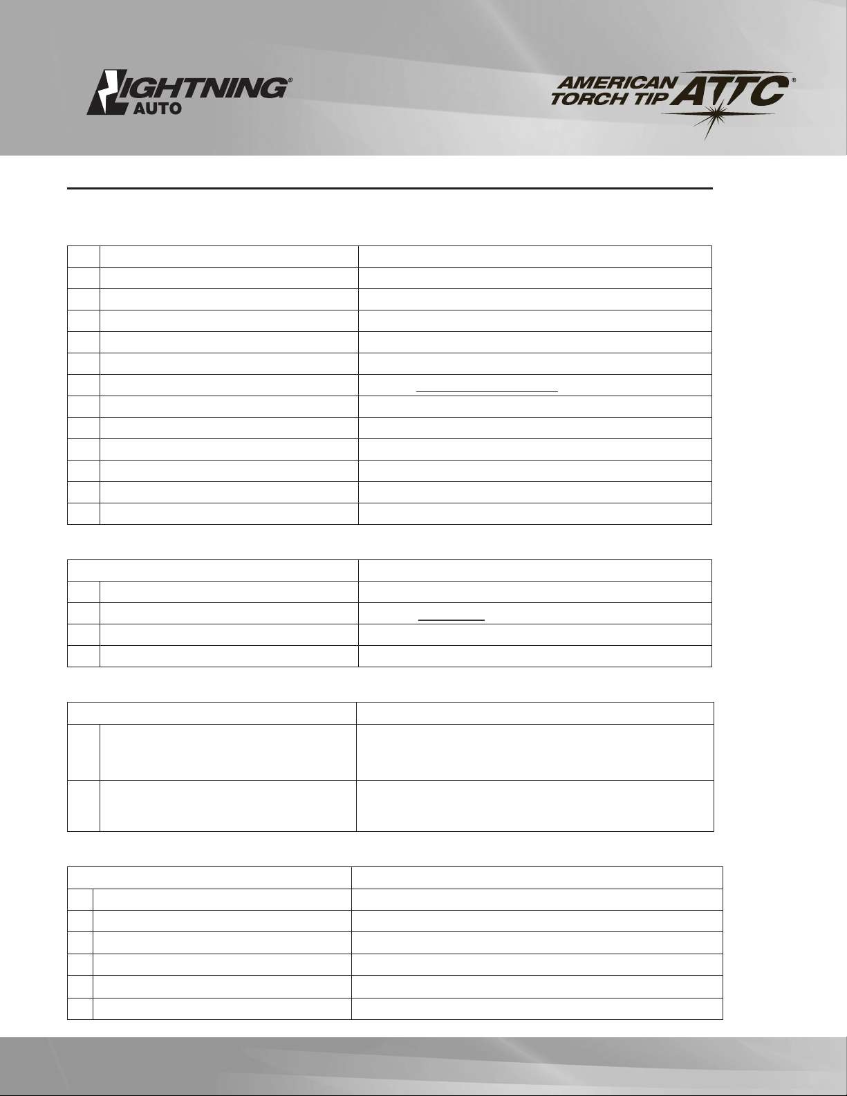
PART NUMBERING SYSTEM
Wire Size
30 .030”
35 .035”
10 1.0 mm
45 .045”
52 .052”
116 1/16”
332 3/32”
364 3/64” al
564 5/64”
Gooseneck (opt)
500 180º
522 22º
545 45º
560 60º
Cable Length
03 3 feet
3.5 3.5 feet
04 4 feet
06 6 feet
08 8 feet
10 10 feet
12 12 feet
15 15 feet
LIGHTNING HANDLE
LLightning
L E 53 04 - 45 - 560
Gun Model
53 500 amp
Power Pin
TTweco
EEuro
LN Lincoln
MMiller
100% Duty Cycle 60% Duty Cycle
Co2 Mixed Gas Co2 Mixed Gas
500 amps 350 amps 650 amps 500 amps
Amperage Ratings (duty cycle)
Reliable Automatic Welding Equipment
The Lightning®AUTO MIG gun is made to stand up to the high heat conditions typical in the
production environment. Lightning®precision consumables are designed to reduce change-out
related downtime. All gun components and consumables are made in the USA.
High Strength Cable
The outer cover is strengthened using electron beam accelerators which cross-link the polymers
and increase the tear, stretch and abrasion resistance of the cable. Hytrel inner tubing is kink and
impact resistant for smooth and reliable wire feed. The copper strand count of our premium cable
assures long life and maximum productivity.
Lightning®Contact Tips
Tapered seat designed to dissipate heat and maximize electrical conductivity.
Our dual start-point thread allows re-seating of the tip. When wire wear begins to effect
performance, simply rotate the tip 180º to a new wear-point and double the life of the contact tip.
Heavy Duty Handle
Lifetime Warranty on gun body.
Fiber reinforced resin stands up to extreme heat and impact.
Slim compact design.
3
LIGHTNING®
941-753-7557 • FAX:941-753-6917 • 800 342-8477 • sales@attcusa.com • www.AmericanTorchTip.com
3
NOZZLES ID
63-2138 HD * Flush 3/8” (09.5mm)
63-2662 HD 1/8” Stick-Out 5/8” (15.9mm)
63-2150 HD 1/8” Tip Recess 1/2” (12.7mm)
63-2162 HD 1/8” Tip Recess 5/8” (15.9mm)
63-2175 HD 1/8”Tip Recess 3/4” (19.1mm)
64-2562 Extra HD Cu 1/4” Tip Rec. 5/8” (15.9mm)
64-2575 Extra HD Cu 1/4” Tip Rec. 3/4” (19.1mm)
65-2550 HD Cu 1/8” Tip Recess 1/2” (12.7mm)
65-2562 HD Cu 1/8” Tip Recess 5/8” (15.9mm)
65-2575 HD Cu 1/8” Tip Recess 3/4” (19.1mm)
64-2950 HD Bottleneck 1/8 Stick-out 1/2” (12.7mm)
63-2950 HD Bottleneck 1/8 Recess 1/2” (12.7mm)
65-2662 Extra HD 1/8 Stick-out 5/8” (15.9mm)
65-2362 Extra HD Brass 1/8 Stick-out 5/8” (15.9mm)
Threaded versions available for all nozzles.
Add “T” to part number.
CONTACT TIPS ID
63-1130 HD* .030 (0.8mm) .037
63-1135 HD .035 (0.9mm) .043
63-1140 HD .040 (1.0mm) .048
63-1145 HD .045 (1.2mm) .055
63-1152 HD .052 (1.3mm) .063
63-1178 HD 5/64 (2.0mm) .093
63-1193 HD 3/32 (2.4mm) .110
63-1162 HD 1/16” (1.6mm) .073
63-1230 HD Tapered .030 (0.8mm) .037
63-1235 HD Tapered .035 (0.9mm) .043
63-1245 HD Tapered .045 (1.2mm) .055
63-1252 HD Tapered .052 (1.3mm) .063
63-1335 HD CuCr ** .035 (0.9mm) .043
63-1345 HD CuCr .045 (1.2mm) .050
63-1352 HD CuCr .052 (1.3mm) .059
63-1362 HD CuCr 1/16” (1.6mm) .070
63-1378 HD CuCr 5/64” (2.0mm) .093
63-1394 HD CuCr 3/32” (2.4mm) .110
65-1130 Extra HD .030 .037
65-1135 Extra HD .035 .043
65-1145 Extra HD .045 .055
65-1162 Extra HD 1/16 .073
65-1178 Extra HD 5/64 .093
65-1193 Extra HD 3/32 .110
65-11120 Extra HD 7/64 .120
65-11125 Extra HD 1/8 .136
65-1235 Extra HD .035 tprd .043
65-1245 Extra HD .045 tprd .055
65-1252 Extra HD .052 tprd .063
65-1335 Extra HD CuCr .035 .040
65-1345 Extra HD CuCr .045 .050
65-1352 Extra HD CuCr .052 .060
65-1362 Extra HD CuCr 1/16 .070
GAS DIFFUSERS & RETAINER
63-3201 Diuser for HD Contact Tip
63-3104 Nozzle Retainer (for 63-3201 above)
63-3103 Diuser HD
63-3116 R/M Thread-on Diuser HD
65-3116 R/M Thread-on Extra Heavy Duty Diuser
65-3103 Diuser Extra HD
65-3103-2 Robotic Extra HD
63-3301 Gas Diuser O-Ring
SHOCK WASHERS
63-6202
63-6202HD (Heavy Duty)
LIGHTNING®GOOSENECKS
65-5100A Fixed 180º
65-5122A Fixed 22º
65-5145A Fixed 45º
65-5160A Fixed 60º
LINERS
Wire Size Length Part# OD
.023” (.6mm) 15’ 64-4115 0.150
.035” (.9mm) 15’ 62-4315 0.156
.035” (.9mm) 25’ 62-4325 0.156
.045” (1.6mm) 15’ 62-4515 0.156
.045” (1.6mm) 25’ 62-4525 0.156
.030” (.8mm) 15’ 64-4215 0.182
.035” (.9mm) 10’ 64-4310 0.175
.035” (.9mm) 15’ 64-4315 0.175
.035” (.9mm) 25’ 64-4325 0.175
.035” (.9mm) 25’ 64-4325 0.175
.035” (.9mm)al 15’ 64-4415 0.189
.045” (1.6mm) 10’ 64-4510 0.189
.045” (1.6mm) 15’ 64-4515 0.189
.045” (1.6mm) 25’ 64-4525 0.189
3/64” (1.6mm) 10’ 64-4510 0.189
3/64” (1.6mm) 15’ 64-4515 0.189
3/64” (1.6mm) 25’ 64-4525 0.189
.52” (1.6mm) 10’ 64-4510 0.189
.52” (1.6mm) 15’ 64-4515 0.189
.52” (1.6mm) 25’ 64-4525 0.189
1/16” (1.6mm) 10’ 64-4510 0.189
1/16” (1.6mm) 15’ 64-4515 0.189
1/16” (1.6mm) 25’ 64-4525 0.189
3/64-1/16al 15’ 64-4615 0.189
5/64-3/32 15’ Flat 64-4715 0.189
5/64-3/32 25’ Flat 64-4725 0.21
5/64 & 1/16” FC 10’ 64-4815 0.21
.035 – .045 15’ 64-4915 0.192
(for S.S. Wire)
NOTE: 65-11xx series tips are only to be used with 65 series Lightning® diusers.

4
LIGHTNING®
941-753-7557 • FAX:941-753-6917 • 800 342-8477 • sales@attcusa.com • www.AmericanTorchTip.com
4
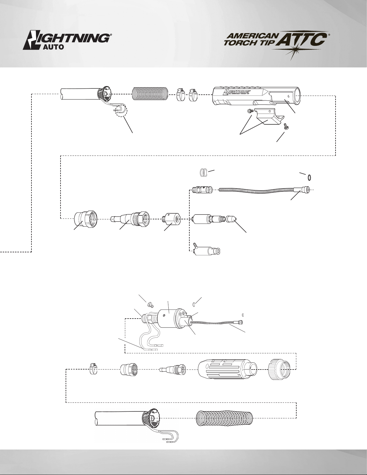
Contact Tip HD
Nozzle (Copper)
64-6301A (4/500A) 63-6302 (2/3/400A)
65-6302 (500A)
63-6502
Clamps
Front-End Housing
64-6201 65-7902 (500A)
Spring Guard
Unicable Assembly
Mounting Screw
Cone NutConnector Cone
Body Set Screw
63-6501
See Chart on page 3
See Chart on page 3
Gooseneck
See Chart on page 3
Shock Washer
Diffuser Assy. 1 Pc
63-3103
63-6202 (HD)
63-6601A
Body Assy
Front-End Assembly
64-6506
5
LIGHTNING®
941-753-7557 • FAX:941-753-6917 • 800 342-8477 • sales@attcusa.com • www.AmericanTorchTip.com
5
Connector Cone
64-6301 (4/500A)
Cone Nut
63-6302 (400A)
65-6302 (500A)
Liner O-ring
64-9001
Liner Conduit Liner
See Chart on
page 3
Power Pin O-ring
64-8202
Power Pin
Mount
64-8208
Pin (Tweco #4)
64-8211
Pin (Miller)
64-8311
Pin (Lincoln)
64-8411
Guide Cap
64-8303 (.035-1/16)
64-8304 (5/64-3/32)
Housing & Screws
63-6101LP
Unicable
See Chart on page 3
Control Plug
Connector
64-7909
Clamp
64-7907 (400A)
65-7902 (500A)
Spring Guard
63-6502 Handle
64-6106
Screws
64-6501
European Assembly
Back-End Assembly
Spring Guard - Euro
63-6504
Unicable
Euro Male Connector
64-7910
Handle
64-8107
Connector Cone
64-6301 (4/500A) Hand Nut
64-8104
Clamp
65-7902 (500A)
Cone Nut
65-6302 (500)
Euro Female
Connector
64-8102-4
Adapter Fitting (Euro)
64-8109 Included
w/64-8101
Mounting Screw
64-8106
Liner O-Ring
64-9001
Conduit Liner
See chart on page 3
Quick Connect
Power Pin Assy.
64-8101 Power Pin O-Ring
64-8103
Liner Adapter
64- 8114
Gas Nipple
63- 8113

6
LIGHTNING®
941-753-7557 • FAX:941-753-6917 • 800 342-8477 • sales@attcusa.com • www.AmericanTorchTip.com
6
NOZZLE AND CONTACT TIP SYSTEMS
IMPORTANT
Shock washer must be in place before welding to maintain insulation of
gooseneck. Be sure all parts are tightened will before welding.
When using the heavy duty retaining head make sure it is tightened with
a 11/16” wrench to prevent overheating of contact tip.
To prevent scoring on heavy duty retaining head do not use pliers.
REMOVAL AND REPLACEMENT
Pull slip-on nozzles o with a clockwise twisting motion.
When installing nozzle, exposed insulator should nest inside shock
washer to assure concentricity.
Shock washers are positioned on the end of the gooseneck with
the large insulated counterbore facing the nozzle.
Replace nozzle retainer with deep counterbore toward the gooseneck.
Tighten until retainer and shock washer are secure.
THREAD-ON (OPTIONAL FOR TWECO HD)
Thread-on nozzle system does not require nozzle retainer and
cannot be used with heavy duty head.
Shockwasher must be in place.
External gooseneck thread can be cleaned with a 9/16”-18 die.
1.1 LINER REPLACEMENT
TOOLS REQUIRED
Vise
5/64 Allen wrench
Lineman pliers
1. Remove nozzle, contact tip and tip holder from gooseneck. (Not shown)
2. With gun straightened, loosen liner set screw on quick connect power
pin at back end of gun using a 5/64” Allen wrench. (See Figure 1)
3. Using pliers, grip liner and remove from gun.
4. Install new liner by feeding through gun. Use short strokes to avoid kinking.
Use clockwise rotation as needed.
5. Be sure o-rings on liner head seats into inside bore of power pin.
6. Tighten set screw on power pin to secure liner. Do not overtighten.
Nozzle (Copper) Contact Tip HD
Contact Tip HD Tprid
Diffuser Assy. 500A
NOTE: Any of the above nozzle and contact tip systems can be used on the LIGHTNING
GUN 50 AMP models. (See chart page 3)
7
LIGHTNING®
941-753-7557 • FAX:941-753-6917 • 800 342-8477 • sales@attcusa.com • www.AmericanTorchTip.com
7
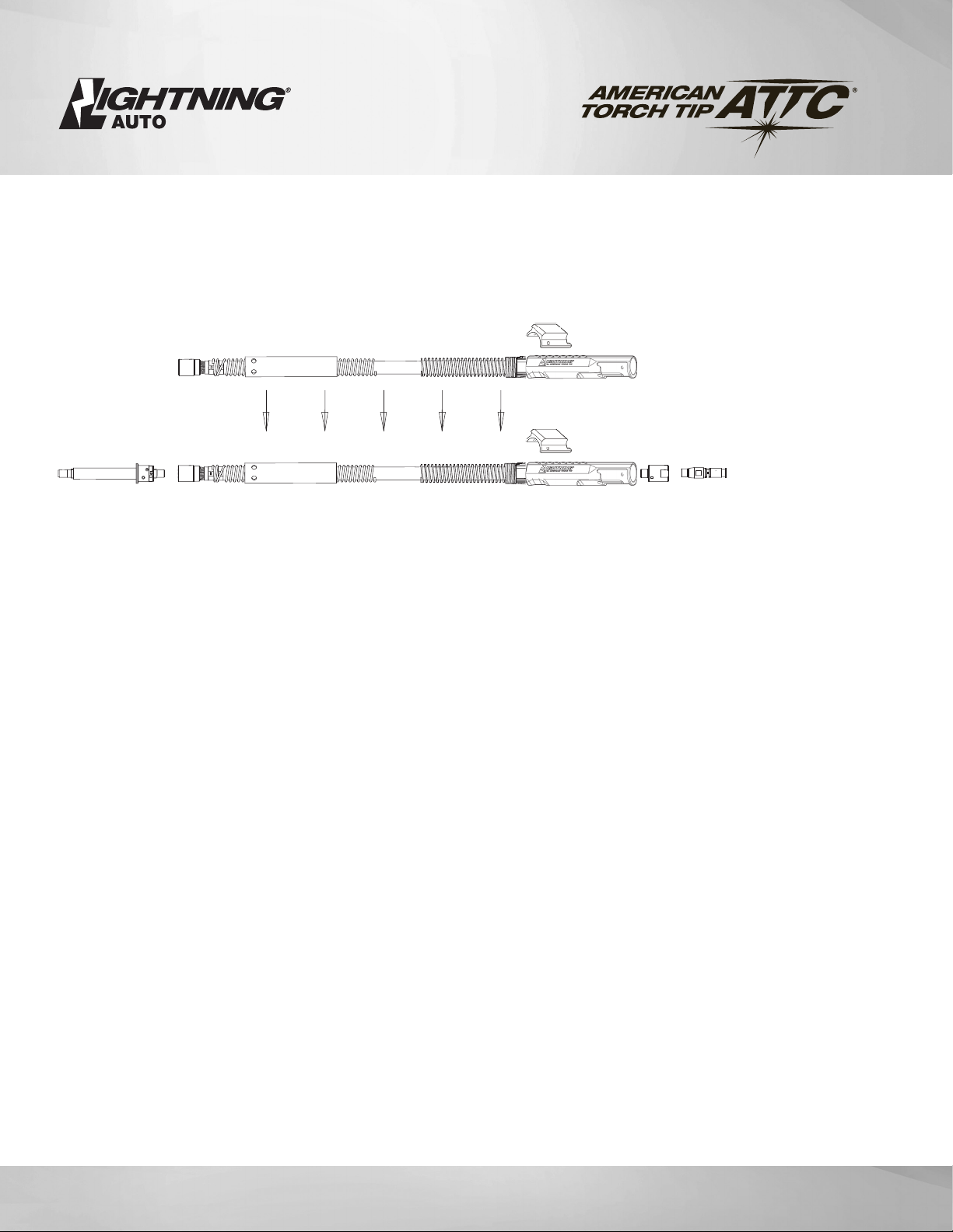
UNICABLE REPAIR / REPLACEMENT
STEP #1
•Remove liner from gun (See Section 2.5 LINER REPLACEMENT).
• Mount neck in vise.
• Remove housing screws and slide housing back (front and back).
• Loosen connector cone from neck using 1” (25 mm) wrench.
• Remove from vise and thread out neck by hand.
• Cable connection between cone and crimp ring should not be disturbed.
• Unthread power pin and remove using 1 1/4” (32 mm) on connector cone and a 5/8” (16
or 3/4” (19 mm) wrench on power pin. Install new power pin.
• Retrieve front and rear housing. Slide housings onto new unicable assembly.
• Repeat procedure in reverse to assemble remaining components.
REPLACEMENT
UNICABLE
USED UNICABLE
8
LIGHTNING®
941-753-7557 • FAX:941-753-6917 • 800 342-8477 • sales@attcusa.com • www.AmericanTorchTip.com
8
A. Wire not feeding or bumpy feeding
Possible Cause Possible Solution
1. Feeder relay / malfunction Consult feeder manufacturer.
2. Broken control lead Connect spare control leads.
3. Poor adaptor connection Test and replace leads and/or contact pins.
4. Incorrect type of drive roll Use manufacturers recommended drive rolls
5. Improper drive rolls size Replace with proper size.
6. Drive roll tension misadjusted Adjust tension at feeder.
7. Burn back to contact tip See “E. Contact tip burn back.”
8. Wrong size liner Replace with correct size.
9. Buildup inside of liner Replace liner, check condition of electrode.
10. Worn drive roll Replace with new drive roll.
11. Improper guide tube relationship Eliminate all gaps in electrode path.
12. Improper wire guide diameter Replace with proper guide diameter.
13. Gaps at liner into gas diuser Reset liner and lock or replace with new liner
B. Premature contact tip failure
Possible Cause Possible Solution
1. Improper voltage or wire feed speed Set parameters.
2. Erratic wire feeding See “G. Erratic arc.”
3. Improper tip stickout Adjust nozzle/tip relationship.
4. Improper electrode stickout Change length of wire stickout.
C. MIG Gun running hot
Possible Cause Possible Solution
1. Exceeding duty cycle Replace with properly rated duty cycle MIG Gun.
Decrease parameters to within Gun rating.
2.
Loose or poor power connection Clean and retighten all electrical connection.
Check rating and condition of ground clamp.
D. Porosity in weld
Possible Cause Possible Solution
1. Nozzle/Insulator/O-rings worn Replace.
2. Retaininghead spring/band Replace retaining head.
3. Extreme heat or duty cycle Use X-heavy-duty consumables.
4. Gas not getting to the weld Check gas regulator/flowmeter/cylinder
5. Gas ports plugged Clean or replace gas diuser/nozzle.
6. Loose fittings or cut gas hose Tighten or repair hose lines.
Lightning® Troubleshooting
9
LIGHTNING®
941-753-7557 • FAX:941-753-6917 • 800 342-8477 • sales@attcusa.com • www.AmericanTorchTip.com
9
Lightning® Troubleshooting
E. Contact tip burn back
Possible Cause Possible Solution
1. Improper voltage and/or wire feed speed Set parameters.
2. Erratic wire feeding See “G. Erratic arc.”
3. Improper tip stickout Adjust nozzle / tip relationship.
4. Improper electrode stickout Adjust torch to base metal relationship.
5. Faulty ground Repair all cables and connectors.
F. Tip disengages from retaining head
Possible Cause Possible Solution
1. Worn retaining head Replace tip and/or retaining head.
2. Improper tip installation Finger tighten then slightly tighten with correct tool.
G. Erratic arc
Possible Cause Possible Solution
1. Worn contact tip Replace.
2. Buildup inside of liner Replace liner, check condition of electrode.
3. Wrong tip size Replace with correct tip size.
4. Incorrect welding parameters Use wire manufacturers parameters.
H. Excess spatter
Possible Cause Possible Solution
1. Improper machine parameters Adjust parameters.
2. Incorrect tip or installation Adjust nozzle / tip relationship.
3. Incorrect nozzle or shielding Use correct nozzle and shielding gas coverage.
4. Contaminated wire or work piece Replace wire and clean work piece.
I. Discolored Liner
Possible Cause Possible Solution
1. Short circuit to electrode Check for wire short circuiting in feeder
2. Cuts in outer jacket, copper exposed Replace gun.

10
LIGHTNING®
941-753-7557 • FAX:941-753-6917 • 800 342-8477 • sales@attcusa.com • www.AmericanTorchTip.com
Nozzle 64-2387
7/8” Bore
1/4” Recess
Brass
1.062” O.D.
Straight Bore
64-2950
1/2” Bore
1/8” Stickout
Brass
0.938” O.D.
Straight Bore
64-2962
5/8” Bore
Flush
Copper
1.062” O.D.
Bottle Neck
65-2562
5/8” Bore
1/8” Recess
Copper
1.062” O.D.
65-2362
5/8” Bore
1/8” Stickout
Brass
1.062” O.D.
65-2375
3/4” Bore
1/4” Recess
Brass
1.120” O.D.
Straight Bore
65-2575
3/4” Bore
1/8” Recess
Copper
1.062” O.D.
65-2662
5/8” Bore
1/8” Stickout
Copper
1.062” O.D.
65-2550
1/2” Bore
1/8” Recess
Copper
1.062” O.D.
Diuser 63-3103 63-3103 63-3103 63-3103 63-3103 63-3103 63-3103 63-3103 63-3103
Tip 63-11XX 63-11XX 63-11XX 63-11XX 63-11XX 63-11XX 63-11XX 63-11XX 63-11XX
Nozzle 63-2138
3/8” Bore
Flush
Copper
0.938” O.D.
63-2150
1/2” Bore
1/8” Recess
Copper
0.938” O.D.
63-2162
5/8” Bore
1/8” Recess
Copper
0.938” O.D.
63-2175
3/4” Bore
1/8” Recess
Copper
0.938” O.D.
Straight Bore
63-2362
5/8” Bore
1/8” Recess
Brass
1.120” O.D.
Straight Bore
63-2662
5/8” Bore
1/8” Stickout
Copper
0.938” O.D.
63-2950B
1/2” Bore
1/8” Recess
Brass
0.938” O.D.
Straight Bore
64-2562
5/8” Bore
1/4” Recess
Copper
1.062” O.D.
64-2575
3/4” Bore
1/4” Recess
Copper
1.062” O.D.
Diuser 63-3103-2 63-3103-2 63-3103 63-3103 63-3103 63-3103 63-3103-2 63-3103 63-3103
Tip 63-12XX 63-11XX 63-11XX 63-11XX 63-11XX 63-11XX 63-11XX 63-11XX 63-11XX
XX denotes wire size.
See chart on page 3 for details.
Visit LightningMIG.com for more information
and helpful MIG resources, including catalogs, videos and articles.
MIG Consumable Parts Reference
All Lightning® consumables are interchangable for custom configurations.
All nozzles are available in threaded versions for use with threaded diuser.
11
LIGHTNING®
941-753-7557 • FAX:941-753-6917 • 800 342-8477 • sales@attcusa.com • www.AmericanTorchTip.com
11
11
LIGHTNING®
Warranty Terms
This warranty shall not apply to any product that has been modified or used in a manner inconsistent with ATTC’s installaton
instructons and operatng guidelines. Within the warranty periods listed above and at ATTC’s sole discreton, ATTC will repair or replace
any warranted parts or components that fail due to such defects in material or workmanship. ATTC must be notfied within thirty (30)
days of such defect or failure, at which tme ATTC will determine if a Return Goods Authorizaton (RGA) is justfied and issue an RGA
number, authorizaton of a RGA number shall not be unreasonably withheld. ATTC will supply a RGA form, which must be included
with the returned products for inspection by ATTC. Shipping and packing costs shall be the responsibility of the party returning the
goods. Once received, ATTC shall inspect and determine if a warranty claim is justified and at ATTC’s sole discreton authorize a repair
or replacement. Once authorizaton has been granted ATTC shall provide instructons on the warranty claim procedures to be followed.
Where authorized, repair or replacement consttutes the sole remedy for breach of warranty and expressly excludes claims for lost
revenue, down tme and other consequental damages. The warranty is limited to the conditons stated above and excludes, to the
fullest extent permited by law, all conditons, warrantes and representatons express or implied by statue, law or otherwise in relaton to
the supply or delay in supplying the goods/services. There are no agreements, promises or understandings, either verbal or writen that
are not fully expressed in this warranty. This warranty may be amended or altered only if agreed to in writing and signed by ATTC.
ATTC Limited Warranty 0516
LIMITED WARRANTY − Subject to the terms and conditions below
American Torch Tip Co. (ATTC) warrants its products to the original end user for the periods listed below:
PLASMA MIG
LIFETIME
*PHD and PHDX Torch Bodies
LIFETIME
*Lightning® Handle and Trigger Switch
ONE YEAR
*Lightning® Semi-Automatic MIG Guns
*Lightning® Robotic MIG Guns
*Lightning® Fixed Automation MIG Guns
180 DAYS
*All Other Gun Models
GAS APPARATUS TIG
THREE YEARS
*Complete Oxy-Fuel Kit Components
*Regulators/Flowmeters/Flowregulators
*Torches, Handles & Cutting Attachments
ONE YEAR
*TIG Torches
THERMAL SPRAY
ONE YEAR
*Thermal Spray Guns
*Limited Warranty on Manufacturing and Material Defects. Warranty Terms Do Not Apply to Consumable Products.

12
LIGHTNING®
941-753-7557 • FAX:941-753-6917 • 800 342-8477 • sales@attcusa.com • www.AmericanTorchTip.com
For selecting the Lightning® MIG Gun. The Lightning® Gun is for welding professionals who want
durability and comfort while working in harsh welding environments. This technical guide with
instructions and illustrations is designed to make it easy to maintain your Lightning®Gun. Please
read and follow all the safety procedures. For technical support, please call our Customer Service
department at 1-800-371-8477 between 8:00 AM and 5:00 PM EST Monday through Friday. We are
committed to providing the best-quality products and services. We are constantly working to improve
our products. We would appreciate hearing your suggestions.
THANK YOU
Robotic MIG GunAutomatic MIG Gun
The Family of MIG Guns, Consumables and Accessories
Semi-Auto MIG Gun Large Curve MIG Gun Small Curve MIG Gun
Made in the USA by
American Torch Tip
MAR-TECH-MIG-011
This manual suits for next models
1
Table of contents


