AudioArts Air 3 User manual
TECHNICAL MANUAL
March 2010
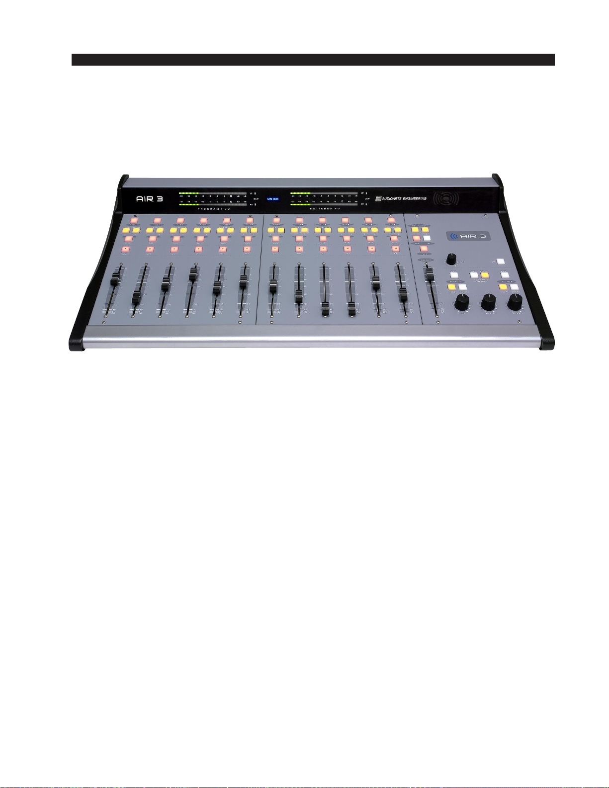
AIR 3
R
ADIO
C
ONSOLE

R-16 / Dec 1997
AIR 3 Radio Console Technical Manual - 1st EditionAIR 3 Radio Console Technical Manual - 1st Edition
AIR 3 Radio Console Technical Manual - 1st EditionAIR 3 Radio Console Technical Manual - 1st Edition
AIR 3 Radio Console Technical Manual - 1st Edition
©2010 Audioarts®Engineering*
AUDIOARTS ENGINEERING
600 Industrial Drive
New Bern, North Carolina 28562
252-638-7000
*a division of Wheatstone Corporation
AIR 3/ March 2010
AA
AA
ATTENTIONTTENTION
TTENTIONTTENTION
TTENTION
RR
RR
READEAD
EADEAD
EAD MM
MM
M
EE
EE
E!!
!!
!
AIR 3 / May 2010
Attention!
FF
FF
Federal Communications Commission (FCC) Complianceederal Communications Commission (FCC) Compliance
ederal Communications Commission (FCC) Complianceederal Communications Commission (FCC) Compliance
ederal Communications Commission (FCC) Compliance
Notice:Notice:
Notice:Notice:
Notice:
Radio FRadio F
Radio FRadio F
Radio Frequency Noticerequency Notice
requency Noticerequency Notice
requency Notice
NOTE:NOTE:
NOTE:NOTE:
NOTE: This equipment has been tested and found to comply with the
limits for a Class A digital device, pursuant to Part 15 of the FCC rules. These
limits are designed to provide reasonable protection against harmful
interference when the equipment is operated in a commercial environment.
This equipment generates, uses, and can radiate radio frequency energy
and, if not installed and used in accordance with the instruction manual,
may cause harmful interference to radio communications. Operation of this
equipment in a residential area is likely to cause harmful interference in
which case the user will be required to correct the interference at his own
expense.
!
This is a Class A product. In a domestic environment, thisThis is a Class A product. In a domestic environment, this
This is a Class A product. In a domestic environment, thisThis is a Class A product. In a domestic environment, this
This is a Class A product. In a domestic environment, this
product may cause radio interference, in which case, theproduct may cause radio interference, in which case, the
product may cause radio interference, in which case, theproduct may cause radio interference, in which case, the
product may cause radio interference, in which case, the
user may be required to take appropriate measures.user may be required to take appropriate measures.
user may be required to take appropriate measures.user may be required to take appropriate measures.
user may be required to take appropriate measures.
This equipment must be installed and wired properly in order to assure
compliance with FCC regulations.
Caution!Caution!
Caution!Caution!
Caution!
Any modifications not expressly approved in writing byAny modifications not expressly approved in writing by
Any modifications not expressly approved in writing byAny modifications not expressly approved in writing by
Any modifications not expressly approved in writing by
Audioarts could void the user's authority to operate this equipment.Audioarts could void the user's authority to operate this equipment.
Audioarts could void the user's authority to operate this equipment.Audioarts could void the user's authority to operate this equipment.
Audioarts could void the user's authority to operate this equipment.

AA
AA
ATTENTIONTTENTION
TTENTIONTTENTION
TTENTION
RR
RR
READEAD
EADEAD
EAD MM
MM
M
EE
EE
E!!
!!
!
AIR 3 / Apr 2010
Attention!
IMPORTIMPORT
IMPORTIMPORT
IMPORTANT SAFETY INSTRUCTIONSANT SAFETY INSTRUCTIONS
ANT SAFETY INSTRUCTIONSANT SAFETY INSTRUCTIONS
ANT SAFETY INSTRUCTIONS
THIS PRODUCT IS INTENDED FOR INDOOR USE ONLTHIS PRODUCT IS INTENDED FOR INDOOR USE ONL
THIS PRODUCT IS INTENDED FOR INDOOR USE ONLTHIS PRODUCT IS INTENDED FOR INDOOR USE ONL
THIS PRODUCT IS INTENDED FOR INDOOR USE ONLYY
YY
Y
When using an electrical appliance, basic safety precautions should always be followed.
DANGERDANGER
DANGERDANGER
DANGER - To reduce risk of electric shock read all instructions before using this power supply.
A power supply should never be left unattended when plugged in.
Always unplug this power supply from the main socket immediately after using.
WARNINGWARNING
WARNINGWARNING
WARNING - To reduce risk of burns, fire, electric shock or injury to persons or animals:
1. Use this power supply only for its intended use as described below.
2. Do not use outdoors.
3. Do not allow to be used as a toy. Pay close attention when this power supply is used by, or
near to, children.
4. Use only attachments recommended by the manufacturer.
5. Never operate this power supply if it has a damaged cord or plug, if it has been dropped or
damaged or if it has fallen into water. In such cases return the power supply to an authorized
dealer or service centre for examination or repair.
6. Never drop or insert an object into any openings.
7. Do not operate where aerosol (spray) products are being used or where oxygen is being
administered.
8. This power supply should be used near to a convenient and easily accessible mains socket.

page Contents – 1
AIR 3 / Mar 2010
CONTENTS
AIR 3 Technical Manual
Table of Contents
Chapter 1 – Installation and Power
Unpacking and Installing the Console ........................................1-2
Power Supply ................................................................................1-3
Energizing......................................................................................1-3
Audio and Control Wiring.............................................................1-3
Unbalanced Connections (analog audio) ................................................................. 1-3
Hook-Ups .......................................................................................1-4
Audio Connections.................................................................................................... 1-4
Analog Stereo Inputs ........................................................................................... 1-4
MIC 1 and Mic 2 Inputs........................................................................................ 1-4
MIC 1 and Mic 2 Outputs..................................................................................... 1-4
Caller Connection ................................................................................................ 1-5
PGM Outputs ....................................................................................................... 1-5
External Inputs..................................................................................................... 1-5
Monitor Outputs ................................................................................................... 1-5
USB Output.......................................................................................................... 1-5
Cue Output and Control Connections - DB-25......................................................... 1-6
DB-25 Connections ............................................................................................. 1-6
CUE Output ......................................................................................................... 1-6
Remote Start........................................................................................................ 1-7
MIC 2 Talkback to Cue/CR.................................................................................. 1-7
On Air Tally .......................................................................................................... 1-7
AIR 3 Console Rear Drawing........................................................1-8
Audio Connection Pinout Drawings............................................1-9
Cue Out and Control Connection Drawing ...............................1-11
Chapter 2 - Console Features
Overview ........................................................................................2-2
Inputs .............................................................................................2-3
Analog Mono Mic Level Inputs ................................................................................. 2-3
Analog Stereo Line Level Inputs .............................................................................. 2-3
Outputs ..........................................................................................2-3
USB Port ........................................................................................2-4
Using the USB Port... ............................................................................................... 2-4
... With a MAC........................................................................................................... 2-4
... With a Windows® PC ........................................................................................... 2-4
Other Computers ...................................................................................................... 2-5
GeneralConsiderations............................................................................................ 2-5
Mute and Tally ...............................................................................2-5

page Contents – 2
AIR 3 / Mar 2010
CONTENTS
Console Programming Options ...................................................2-6
PGM/CUE Dipswitch................................................................................................. 2-6
Cue Interrupt........................................................................................................ 2-6
Split Cue, Control Room...................................................................................... 2-6
Split Cue, Headphone ......................................................................................... 2-6
Studio Dim ........................................................................................................... 2-6
Program Mono ..................................................................................................... 2-7
USB Source Dipswitches (internal) .......................................................................... 2-7
CR MUTE/AIR TALLY Dipswitches .......................................................................... 2-7
CR Mutes ............................................................................................................. 2-7
On Air Tally .......................................................................................................... 2-8
Console Layout Drawing ..............................................................2-9
Chapter 3 - Controls and Functions
Input Panel (IP-AIR3).....................................................................3-2
Source Select ...................................................................................................... 3-3
Program Assign ................................................................................................... 3-3
Cue Button........................................................................................................... 3-3
Fader.................................................................................................................... 3-3
ON Button ............................................................................................................ 3-3
Master Panel (MST-AIR3)..............................................................3-4
Caller Input ............................................................................................................... 3-5
Program Assign ................................................................................................... 3-5
Cue Button........................................................................................................... 3-5
TB Button ............................................................................................................. 3-5
Fader.................................................................................................................... 3-5
ON Button ............................................................................................................ 3-5
Caller Set-Ups ..................................................................................................... 3-6
Control Room Monitor............................................................................................... 3-7
Program Select .................................................................................................... 3-7
EXT Switch .......................................................................................................... 3-8
Control Room Level Control ................................................................................ 3-8
Cue Level Control ................................................................................................ 3-8
Headphone Level Control.................................................................................... 3-8
Studio Monitor........................................................................................................... 3-9
Program Select .................................................................................................... 3-9
EXT Switch .......................................................................................................... 3-9
Studio Level Control ............................................................................................ 3-9
TB (Talkback) Button........................................................................................... 3-9
Meters (VU-AIR3) .................................................................................................... 3-10
VU Meter Pairs ................................................................................................... 3-10
Meters Select Button .......................................................................................... 3-10
On Air LED............................................................................................................... 3-10
Chapter 4 - Schematic and Load Sheet Drawings
Console Flow Diagram .................................................................4-2
IP-AIR3 6 Inputs Panel
Schematic ................................................................................................................. 4-3
Load Sheet................................................................................................................ 4-9

page Contents – 3
AIR 3 / Mar 2010
CONTENTS
MST-AIR3 Master Panel
Schematic ............................................................................................................. 4-10
Load Sheet............................................................................................................ 4-15
MTR-AIR3 Meters Card
Schematic ............................................................................................................. 4-16
Load Sheet............................................................................................................ 4-19
CONA3-3 Three Connector Blocks Card
Schematic ............................................................................................................. 4-20
Load Sheet............................................................................................................ 4-22
CONA3-4 Four Connector Blocks Card
Schematic ............................................................................................................. 4-23
Load Sheet............................................................................................................ 4-28
Appendices
Appendix 1
AIR 3 Console Performance Specifications ............................A-3
Appendix 2
Replacement Parts List .............................................................A-5

INSTALLATION and POWER
page 1 – 1
AIR 3 / Mar 2010
InstallationandPower
Chapter Contents
Unpacking and Installing the Console ..................................... 1-2
Power Supply ............................................................................. 1-3
Energizing................................................................................... 1-3
Audio and Control Wiring.......................................................... 1-3
Unbalanced Connections (analog audio) ........................................................... 1-3
Hook-Ups .................................................................................... 1-4
Audio Connections.............................................................................................. 1-4
Analog Stereo Inputs ..................................................................................... 1-4
MIC 1 and Mic 2 Inputs.................................................................................. 1-4
MIC 1 and Mic 2 Outputs............................................................................... 1-4
Caller Connection .......................................................................................... 1-5
PGM Outputs ................................................................................................. 1-5
External Inputs............................................................................................... 1-5
Monitor Outputs ............................................................................................. 1-5
USB Output.................................................................................................... 1-5
Cue Output and Control Connections - DB-25................................................... 1-6
DB-25 Connections ....................................................................................... 1-6
CUE Output ................................................................................................... 1-6
Remote Start.................................................................................................. 1-7
MIC 2 Talkback to Cue/CR............................................................................ 1-7
On Air Tally .................................................................................................... 1-7
AIR 3 Console Rear Drawing..................................................... 1-8
Audio Connection Pinout Drawings......................................... 1-9
Cue Out and Control Connection Drawing ............................ 1-11

INSTALLATION and POWER
page 1 – 2
AIR 3 / Mar 2010
InstallationandPower
Unpacking and Installing the Console
The AIR 3 console with its power supply, connecting cable, and
technical manual is shipped in one packing box. The console can be
unpackedbyonepersonbygraspingtheconsoleat bothsides,andlifting
itupwardoutofthebox.Removepackingmaterialsandstoretheminthe
box for future use. Carefully place the console on your countertop (the
AIR 3 audio console is designed for countertop placement). Avoid
proximity to any electromagnetic fields, such as large power transform-
ers, motors, and fluorescent lighting fixtures.
NOTE: This console
contains static-sensi-
tive devices. Normal
precautions against
staticdischargeshould
be observed.
15.4"
28.4"
15.4"
4.3"
1.6"

INSTALLATION and POWER
page 1 – 3
AIR 3 / Mar 2010
Power Supply
The AIR 3 console is powered by a factory
supplied power adapter with 100-240V/50-60Hz
input, 50W maximum output power, and a 4 foot
long output cable.
DC Power Output Pinout
The power supply adapter is supplied with a 3-wire grounded AC cord that
shouldbe pluggedinto a“clean” ACpower source,that is,an ACsource thatfeeds
onlythe control room audio gear. Thissource should be a separate feedfrom those
powering lighting, air-conditioning, or any other non-audio machinery.
Energizing
AssumingtheAIR3consolemainframeisproperlyplaced,anditspowersupply
correctlyconnectedtotheconsole,youmaynowenergizethepowersupplyadapter
by plugging it into the AC mains. The console’s individual module switches will
assume factory default settings.
Note: To de-energize the console, unplug the power supply adapter’s AC cord
fromtheACmains.Neverde-energizetheconsolebydisconnectingthecablethat
connects the console and power supply adapter together.
Once you have verified proper power-up, unplug the power supply adapter to de-Once you have verified proper power-up, unplug the power supply adapter to de-
Once you have verified proper power-up, unplug the power supply adapter to de-Once you have verified proper power-up, unplug the power supply adapter to de-
Once you have verified proper power-up, unplug the power supply adapter to de-
energize the console. You may now proceed to wire up audio and control connections.energize the console. You may now proceed to wire up audio and control connections.
energize the console. You may now proceed to wire up audio and control connections.energize the console. You may now proceed to wire up audio and control connections.
energize the console. You may now proceed to wire up audio and control connections.
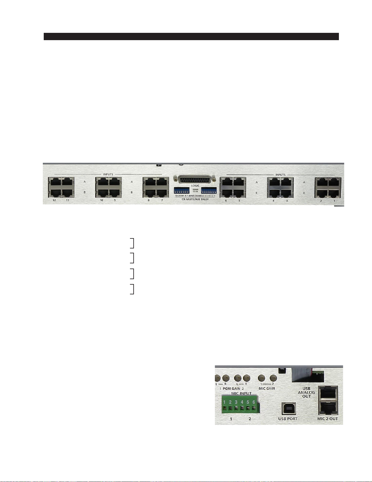
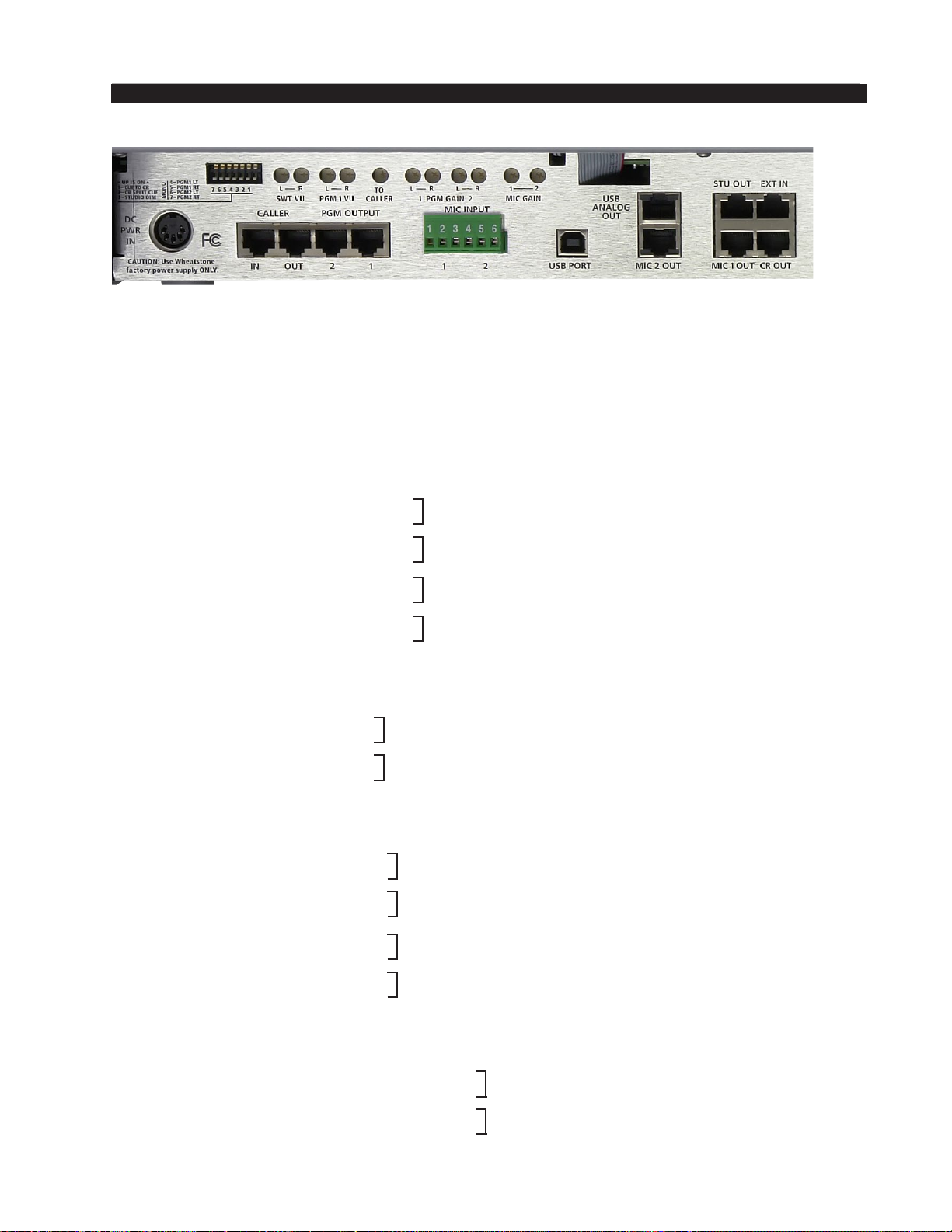
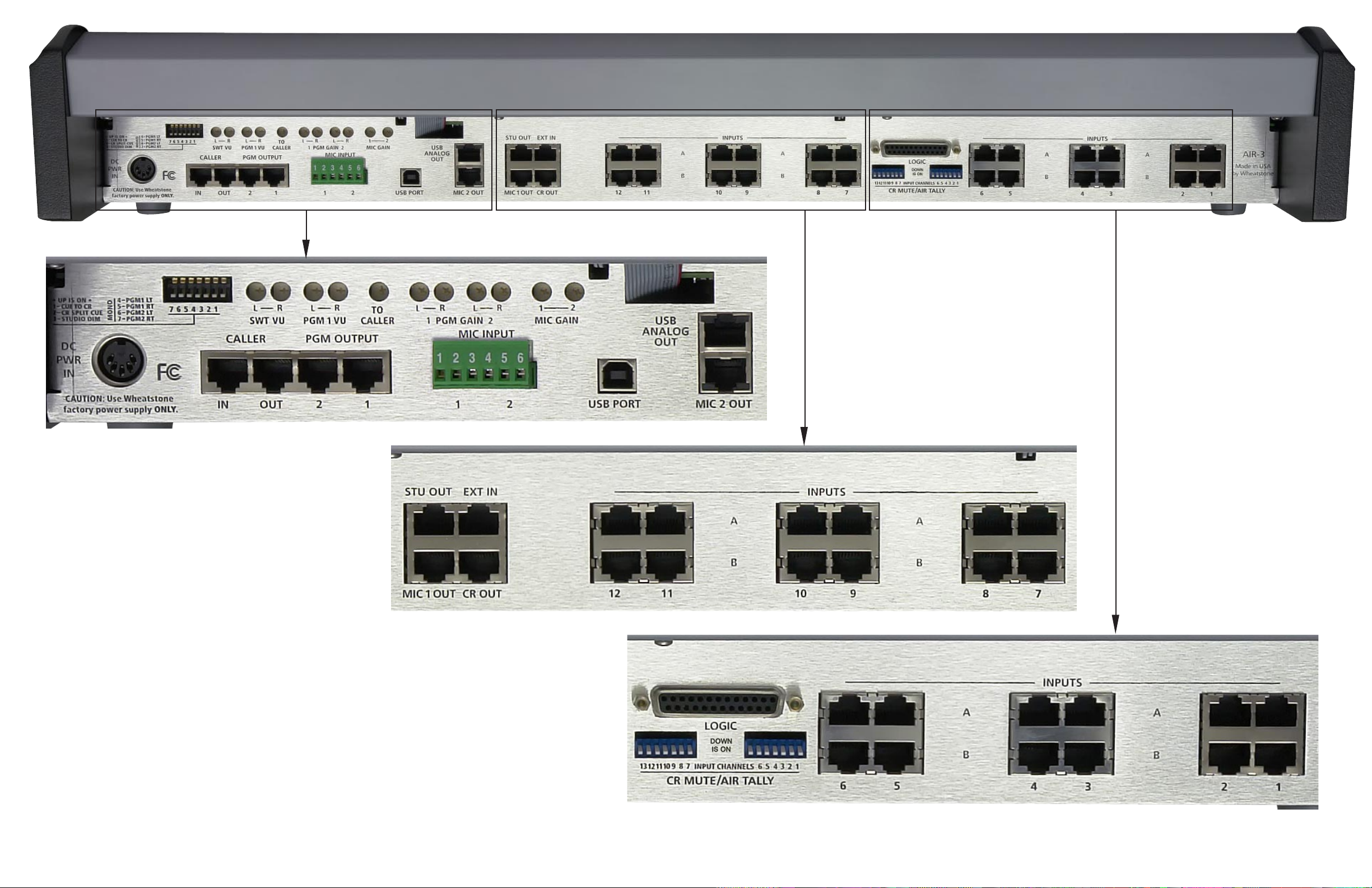
Audio and Control Wiring
All audio I/O connections to the AIR 3 console are made via RJ-45 connectors
and 6-pin plug terminals located on the rear panel of the console. For control
connections there is also a multipin DB-25 connector. See the console’s rear
drawing on page 1-8.
Unbalanced Connections (analog audio)
ANALOGINPUTS—Wiretotheconsolewithtypicalshieldedtwoconductor
cable (like Belden 9451), just as if you were connecting a balanced source. At the
unbalanced source machine’s output, connect the black wire (LO) to the shield.
ANALOG OUTPUTS — AIR 3 consoles use a balanced output circuit which
behaves exactly like the secondary of a high-quality transformer, with no center
tap—thisoutputisbothbalancedandfloating.EithertheHIorLOsideoftheoutput
shouldbe strapped toground,with the outputtaken from the otherside. (Normally
you’d strap LO to ground, and take HIGH to feed your unbalanced equipment.)
Thepowerfeedrecom-
mended in the text is
often installed and re-
ferred to in studios as
an“isolatedACground”
outlet. It is usually or-
ange in color.
PIN # OUTPUT
1 COM
2 COM
3 +5VDC
4 -15V
5 +15V
35241
INSTALLATION and POWER
page 1 – 4
AIR 3 / Mar 2010
Hook-Ups
TherearoftheconsolehasmultipleRJ-45connectorstoplugin24stereolineinputs,
the external input, caller connections to and from hybrid, as well as providing studio,
control room, microphone, PGM, and USB analog output connections. There is also a
6-pin plug terminal (CT7, on the CONA3-4 PCB) provided for microphone inputs.
A DB-25 is provided for control connections and for the Cue output.
There is also a USB port with type B connector available for interfacing with a
computer (see page 2-4 for details).
Pinouts drawings on pages 1-9 through 1-11 show all wiring connection at glance.
AudioConnections
Analog Stereo Inputs - RJ-45 (1 through 12)
The signals are analog stereo; level is +4dBu balanced.
A RJ-45 Pin 1 – HI
A RJ-45 Pin 2 – LO
A RJ-45 Pin 3 – HI
A RJ-45 Pin 6 – LO
B RJ-45 Pin 1 – HI
B RJ-45 Pin 2 – LO
B RJ-45 Pin 3 – HI
B RJ-45 Pin 6 – LO
MIC 1 and MIC 2 Inputs - 6-pin Plug Terminal
All signals are analog mono. The mic input level is normally -50dBu balanced.
Pin 1 – MIC 1 In SH
Pin 2 – MIC 1 In LO
Pin 3 – MIC 1 In HI
Pin 4 – MIC 2 In SH
Pin 5 – MIC 2 In LO
Pin 6 – MIC 2 In HI
MIC 1 and MIC 2 Outputs - RJ-45
All signals are analog mono, unbalanced.
MIC 1 OUT RJ-45 Pin 1 – HI
MIC 1 OUT RJ-45 Pin 2 – SH
MIC 1 OUT RJ-45 Pin 3 – HI
MIC 1 OUT RJ-45 Pin 6 – SH
MIC 2 OUT RJ-45 Pin 1 – HI
MIC 2 OUT RJ-45 Pin 2 – SH
MIC 2 OUT RJ-45 Pin 3 – HI
MIC 2 OUT RJ-45 Pin 6 – SH
INPUT A LT
INPUT A RT
INPUT B LT
INPUT B RT
These connections are to the inputs of
twointernalmicpreamplifiers.Theout-
puts of the mic preamplifiers must be
connected to the desired line inputs
before you will be able to hear the
microphones.Seepage 2-3fordetails.
page 1 – 5
AIR 3 / Mar 2010
INSTALLATION AND POWER
AIR 3 / Dec 2011
Caller Connections - RJ-45
The signals are analog mono; level is +4dBu balanced.
CALLER IN RJ-45 Pin 1 – HI
CALLER IN RJ-45 Pin 2 – LO
CALLER OUT RJ-45 Pin 1 – HI
CALLER OUT RJ-45 Pin 2 – LO
PGM Outputs - RJ-45
The signals are analog stereo; level is +4dBu balanced.
PGM 1 OUT RJ-45 Pin 1 – HI
PGM 1 OUT RJ-45 Pin 2 – LO
PGM 1 OUT RJ-45 Pin 3 – HI
PGM 1 OUT RJ-45 Pin 6 – LO
PGM 2 OUT RJ-45 Pin 1 – HI
PGM 2 OUT RJ-45 Pin 2 – LO
PGM 2 OUT RJ-45 Pin 3 – HI
PGM 2 OUT RJ-45 Pin 6 – LO
External Inputs - RJ-45
The signals are analog stereo; level is +4dBu balanced.
EXT IN RJ-45 Pin 1 – HI
EXT IN RJ-45 Pin 2 – LO
EXT IN RJ-45 Pin 3 – HI
EXT IN RJ-45 Pin 6 – LO
Monitor Outputs - RJ-45
The signals are analog stereo; unbalanced.
CR OUT RJ-45 Pin 1 – HI
CR OUT RJ-45 Pin 2 – SH
CR OUT RJ-45 Pin 3 – HI
CR OUT RJ-45 Pin 6 – SH
STU OUT RJ-45 Pin 1 – HI
STU OUT RJ-45 Pin 2 – SH
STU OUT RJ-45 Pin 3 – HI
STU OUT RJ-45 Pin 6 – SH
USB Output - RJ-45
The signals are analog stereo; unbalanced.
USB ANALOG OUT RJ-45 Pin 1 – HI
USB ANALOG OUT RJ-45 Pin 2 – LO
USB ANALOG OUT RJ-45 Pin 3 – HI
USB ANALOG OUT RJ-45 Pin 6 – LO
PGM 1 LT OUT
PGM 1 RT OUT
PGM 2 LT OUT
PGM 2 RT OUT
EXT LT IN
EXT RT IN
CR LT OUT
CR RT OUT
STU LT OUT
STU RT OUT
USB LT OUT
USB RT OUT
AIR 3 / June 2012

INSTALLATION and POWER
page 1 – 6
AIR 3 / Mar 2010
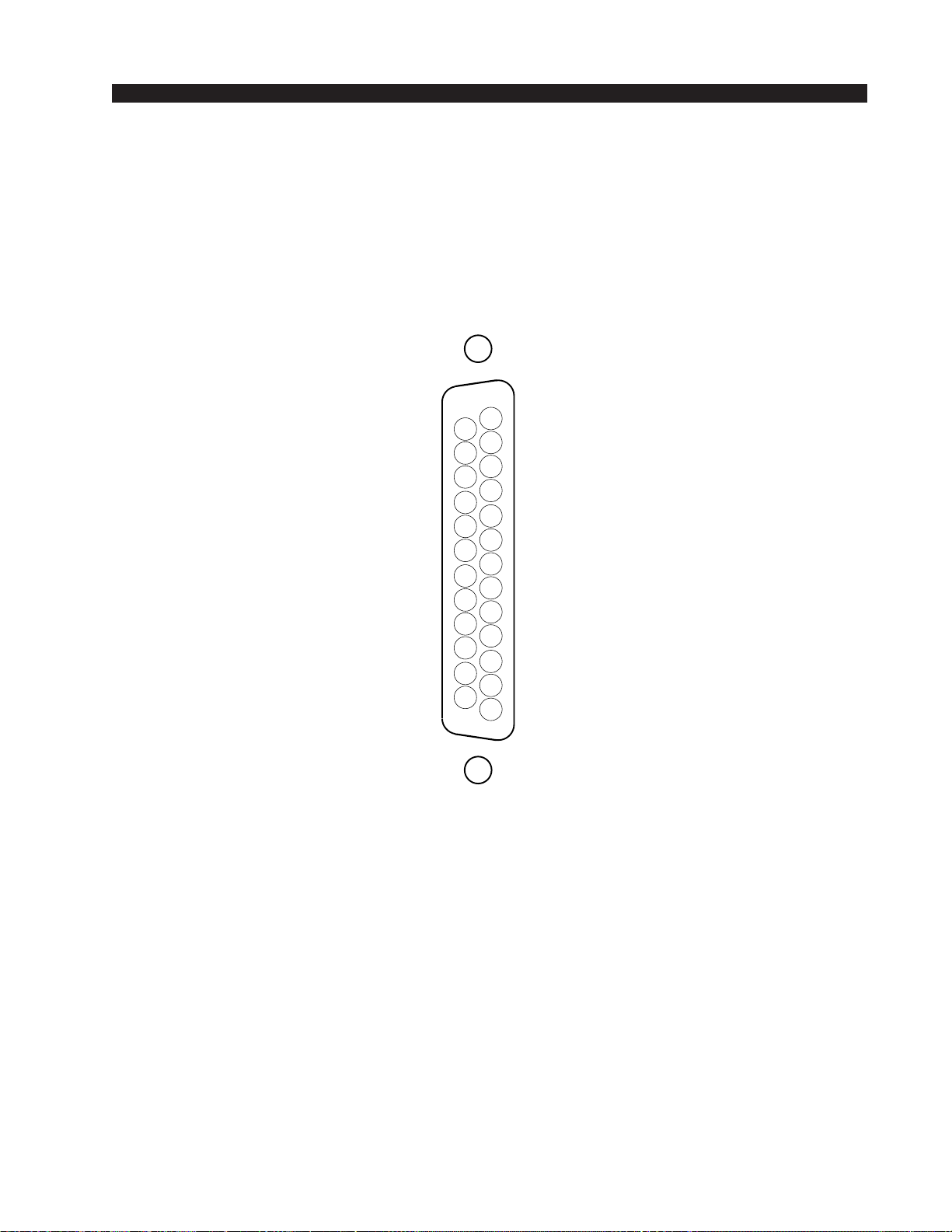
Cue Output and Control Connections - DB-25
Allcontrolports(exceptOnAirTallyandMic2TBtoCue/CR)useopto-isolators.
Functions include Mic 2 TB to Cue/CR, On Air Tally, and Start for remote source
machines. Several pins can be used for the common side connections to remote starts,
as indicated on the pinout below.
DB-25 Connections
Pin 1 – Start Channel 1
Pin 2 – Start Channel 2
Pin 3 – Start Channel 3
Pin 4 – Start Channel 4
Pin 5 – Start Channel 5
Pin 6 – Start Channel 6
Pin 7 – Cue Out
Pin 8 – Cue Out Audio Common
Pin 9 – On Air Tally N.O.
Pin 10 – On Air Tally Common
Pin 11 – Mic 2 TB to Cue/CR
Pin 12 – Mic 2 TB to Cue/CR Common
Pin 13 – Start Common
Pin 14 – Start Common
Pin 15 – Start Common
Pin 16 – Start Common
Pin 17 – Start Common
Pin 18 – Start Common
Pin 19 – Start Channel 7
Pin 20 – Start Channel 8
Pin 21 – Start Channel 9
Pin 22 – Start Channel 10
Pin 23 – Start Channel 11
Pin 24 – Start Channel 12
Pin 25 – Start Phone Channel
Cue Output
The Cue output signal (for feeding an external cue amplifier) is mono unbalanced.
Typical DB-25
connector

INSTALLATION and POWER
page 1 – 7
AIR 3 / Mar 2010
To START Remote Source Machines Using Channel START Switches
EXTERNAL START — Hook up the remote machine’s “start” control pins to the
DB-25connectorcontrolpins;forexample,for channel1wiretoStartChannel1,Pin 1,
and Start Common, either one of the Pins 13 - 18.
MIC 2 Talkback to Cue/Control Room
Thetalkbacktocuelogicinputisusedtoconnectanexternaluser-suppliedbuttonthat
enables the person activating it to talk to the operator in the control room, via the
console’scuespeaker.ProvideaclosurebetweenMic2TBtoCue/CR,Pin11andMic 2
TBtoCue/CR Common,Pin12. Thiswillcause thechannel’spre fadersignalto besent
to the console’s Cue bus, where it may be heard by the console operator. This non-
latching condition continues until the closure is released. (Requires a user-supplied
momentary action TALKBACK switch at the studio microphone location.)
On Air Tally
Lets any programmed channel’s START switch control an on-air light or other
“microphoneon”indicatorataremotelocation.Thiscontrolfunctionprovidesacontact
closurebetweenPin9(OnAirTallyN.O.)andPin10(OnAirTallyCommon)whenever
the module is ON.
This signal can be used to control an externally powered tally light that requires a
continuous closure to function. Current should not exceed 2 amps at 30 volts DC.
page 1 – 8
AIR 3 Console Rear
AIR 3 / Mar 2010
INSTALLATION and POWER
page 1 – 9
AIR 3 / Mar 2010
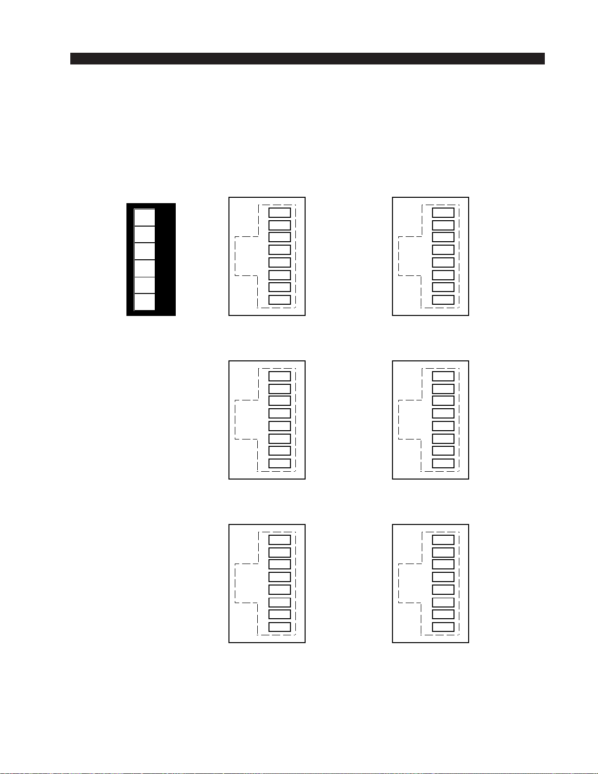
Audio Connection
s
123456
MICS INPUTS
6-pin Plug Terminal
MIC 1 IN SH
MIC 1 IN LO
MIC 1 IN HI
MIC 2 IN SH
MIC 2 IN LO
MIC 2 IN HI
1
2
3
4
5
6
7
8
"MIC 1 OUT" RJ-45
MIC 1 OUT HI 1
2
3
4
5
6
7
8
"MIC 2 OUT" RJ-45
MIC 2 OUT HI
MICS OUTPUT
S
1
2
3
4
5
6
7
8
"A" RJ-45
LINE A LT IN HI
LINE A LT IN LO
LINE A RT IN HI
LINE A RT IN LO
1
2
3
4
5
6
7
8
"B" RJ-45
LINE B LT IN HI
LINE B LT IN LO
LINE B RT IN HI
LINE B RT IN LO
LINE INPUTS
#1 through # 1
2
1
2
3
4
5
6
7
8
"IN" RJ-45
CALLER IN HI
CALLER IN LO
1
2
3
4
5
6
7
8
"OUT" RJ-45
CALLER OUT HI
CALLER OUT LO
CALLE
R
MIC 1 OUT SH MIC 2 OUT SH
MIC 1 OUT HI MIC 2 OUT HI
MIC 1 OUT SH MIC 2 OUT SH
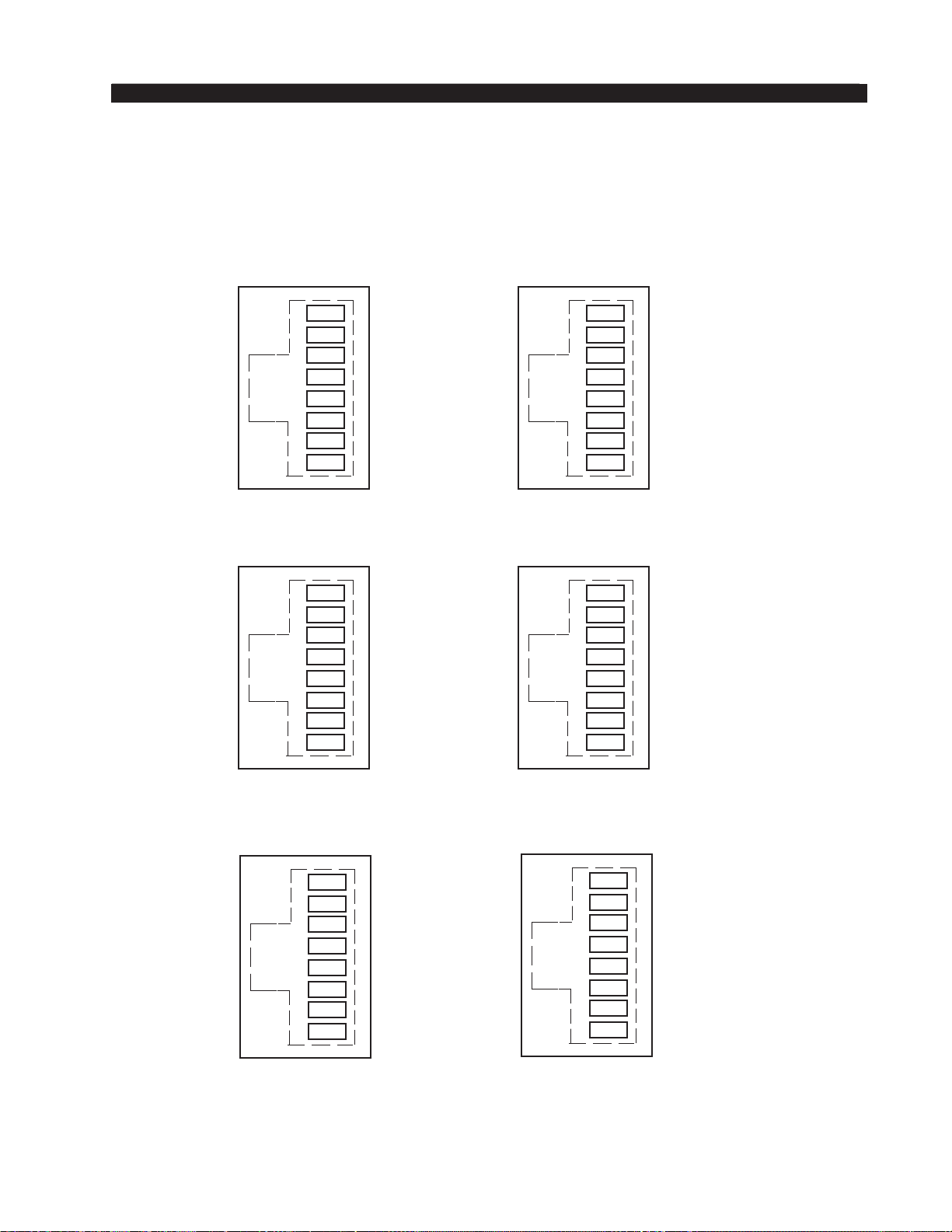
page 1 – 10
AIR 3 / Mar 2010
INSTALLATION AND POWER
AIR 3 / Dec 2011
"USB ANALOG OUT" RJ-45
1
2
3
4
5
6
7
8
"1" RJ-45
1
2
3
4
5
6
7
8
"2" RJ-45
PGM OUTPUTS
1
2
3
4
5
6
7
8
"CR OUT" RJ-45
CR LT OUT HI
CR LT OUT SH
CR RT OUT HI
CR RT OUT SH
1
2
3
4
5
6
7
8
"STU OUT" RJ-45
MONITORS OUTPUT
S
1
2
3
4
5
6
7
8
"EXT IN" RJ-45
EXT LT IN HI
EXT LT IN L
O
EXT RT IN HI
EXT RT IN LO
EXTERNAL INPU
T
1
2
3
4
5
6
7
8
USB LT OUT HI
USB LT OUT LO
USB OUTPU
T
USB RT OUT HI
USB RT OUT LO
PGM 1 LT OUT HI
PGM 1 LT OUT LO
PGM 1 RT OUT HI
PGM 1 RT OUT LO
PGM 2 LT OUT HI
PGM 2 LT OUT LO
PGM 2 RT OUT HI
PGM 2 RT OUT LO
STU LT OUT HI
STU LT OUT SH
STU RT OUT HI
STU RT OUT SH
Audio
C
onnections
INSTALLATION and POWER
page 1 – 11
AIR 3 / Mar 2010
Cue Out and Control Connection
s
LOGIC - DB-25 Connecto
r
START CHANNEL 12
START CHANNEL 11
START CHANNEL 9
START CHANNEL 8
START CHANNEL 7
START COMMON
START COMMON
START COMMON
START COMMON
START COMMON
START COMMON
MIC 2 TB TO CUE/CR COMMON
MIC 2 TB TO CUE/CR
ON AIR TALLY COMMON
ON AIR TALLY N.O.
CUE OUT AUDIO COMMON
CUE OUT
START CHANNEL 6
START CHANNEL 5
START CHANNEL 4
START CHANNEL 3
START CHANNEL 2
START CHANNEL 1
5
4
3
2
1
17
16
15
14
8
7
6
20
19
18
10
9
23
22
21
13
12
11
25
24
START PHONE CHANNEL
START CHANNEL 10

page 2 – 1
AIR 3 / Mar 2010
CONSOLE FEATURES
ConsoleFeatures
Chapter Contents
Overview ..................................................................................... 2-2
Inputs .......................................................................................... 2-3
Analog Mono Mic Level Inputs ............................................................................... 2-3
Analog Stereo Line Level Inputs ............................................................................ 2-3
Outputs ....................................................................................... 2-3
USB Port ..................................................................................... 2-4
Using the USB Port... ............................................................................................. 2-4
... With a MAC......................................................................................................... 2-4
... With a Windows®PC.......................................................................................... 2-4
Other Computers .................................................................................................... 2-5
GeneralConsiderations.......................................................................................... 2-5
Mute and Tally ............................................................................ 2-5
Console Programming Options ................................................ 2-6
PGM/CUE Dipswitch............................................................................................... 2-6
Cue Interrupt...................................................................................................... 2-6
Split Cue, Control Room.................................................................................... 2-6
Split Cue, Headphone ....................................................................................... 2-6
Studio Dim ......................................................................................................... 2-6
Program Mono ................................................................................................... 2-7
USB Source Dipswitches (internal) ........................................................................ 2-7
CR MUTE/AIR TALLY Dipswitches ........................................................................ 2-7
CR Mutes ........................................................................................................... 2-7
On Air Tally ........................................................................................................ 2-8
Console Layout Drawing ........................................................... 2-9
page 2 – 2
AIR 3 / Mar 2010
CONSOLE FEATURES
ConsoleFeatures
Overview
Each AIR 3 console has two Input panels and one Master panel. The Input panel
consistsofsixfaderswithassociatedswitches.TheMasterpanelhasaPHONEsection,
aCONTROLsection,aHEADPHONEsection,andaSTUDIOsection.Eachsectionis
described below.
The basic purpose of the console is to take some of the many audio signals that are
wired to the console inputs, and generate several outputs that combine these inputs in
various groups and at various degrees of loudness, or signal strength. The typical
application is in a radio station where it is desired to develop the signals that the station
will broadcast (the on air signal), as well as several additional signals for recording and
monitoring.
Table of contents


