Aussie Eco Full Inverter EFI Series User manual

0
EFI Series Heat Pumps
-Installation
and
Operation
Manual-
Eco Full Inverter
Swimming Pool Heat Pump

0

0
THANK YOU
Dear Customer,
Thank you for choosing our products and greatly we appreciate your confidence in
us!
These are the ECO Full Inverter Swimming Pool Heat Pumps for heating or cooling
your pool and extending your swimming season.
This is a special Pool heat pumps which has been designed to be as Eco friendly as
possible, using market leading technology and experience.
The EFI is a smart heat pump which controls how to heat your pool most efficiently
and maintain pool temperature, thanks to the full inverter technology.
Our goal is to provide you with an exceptional high performance quality product.
We have produced this manual to assist you in getting the get maximum benefit
and use from your heatpump.
Please read carefully

1

1
TABLE OF CONTENT
INTRODUCTION ............................................................................................................................................. 2
This manual............................................................................................................................................ 2
The unit ................................................................................................................................................. 2
SAFETYINSTRUCTIONS................................................................................................................................... 3
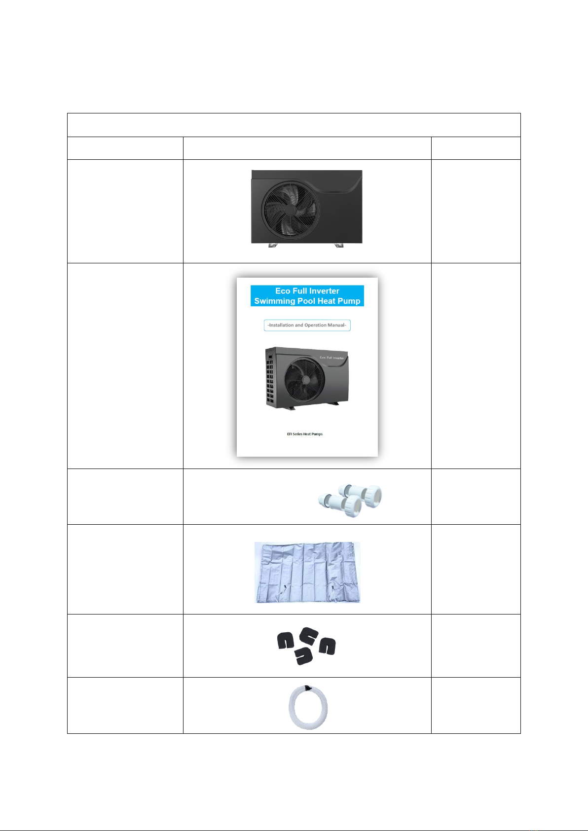
ITEMS INSIDE PRODUCT BOX.......................................................................................................................... 5
OVERVIEW OF THE UNIT ................................................................................................................................ 6
Unit Dimension ...................................................................................................................................... 6
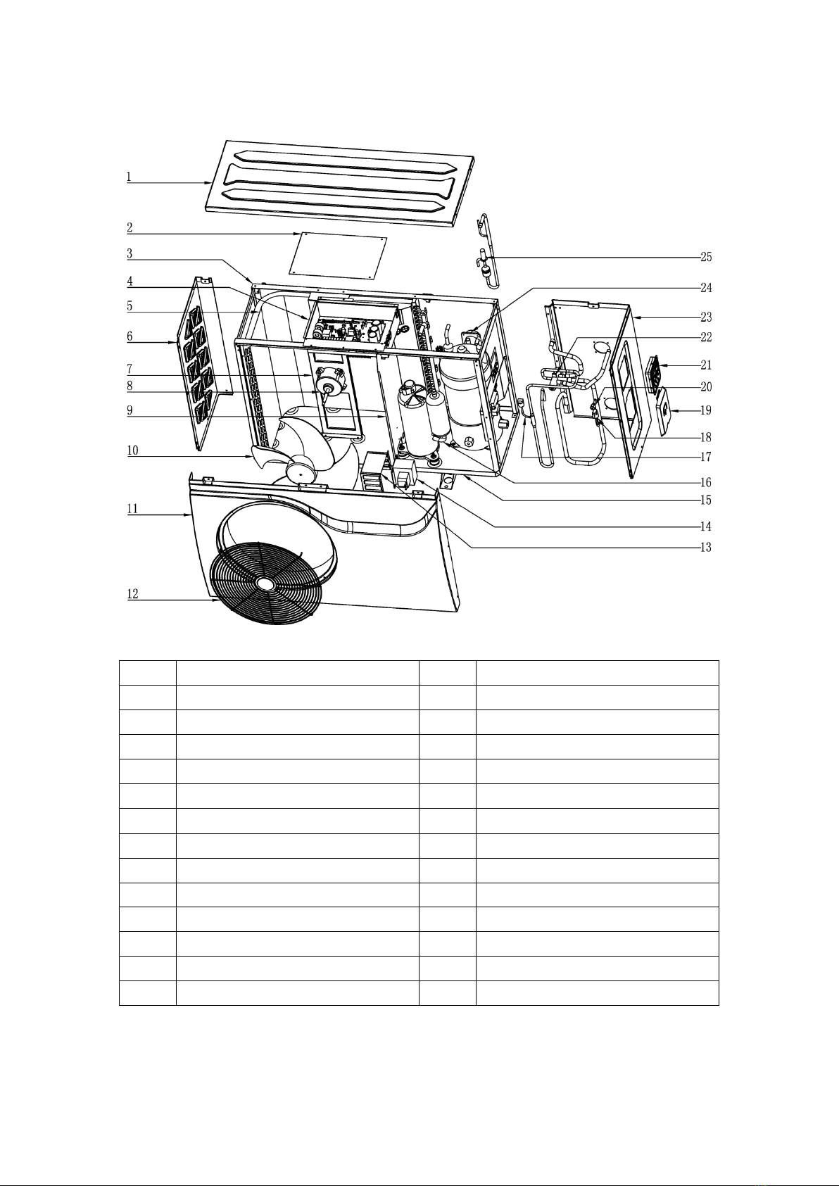
Explode View ......................................................................................................................................... 7
INSTALLATION ............................................................................................................................................... 8
Installation information.......................................................................................................................... 8
Condition of installation ......................................................................................................................... 8
Installation place.................................................................................................................................... 8
To perfect your installation .................................................................................................................... 8
Water connection .................................................................................................................................. 8
Electrical connection .............................................................................................................................10
Trial running..........................................................................................................................................10
OPERATING THE UNIT ...................................................................................................................................11
Controller Instruction............................................................................................................................12
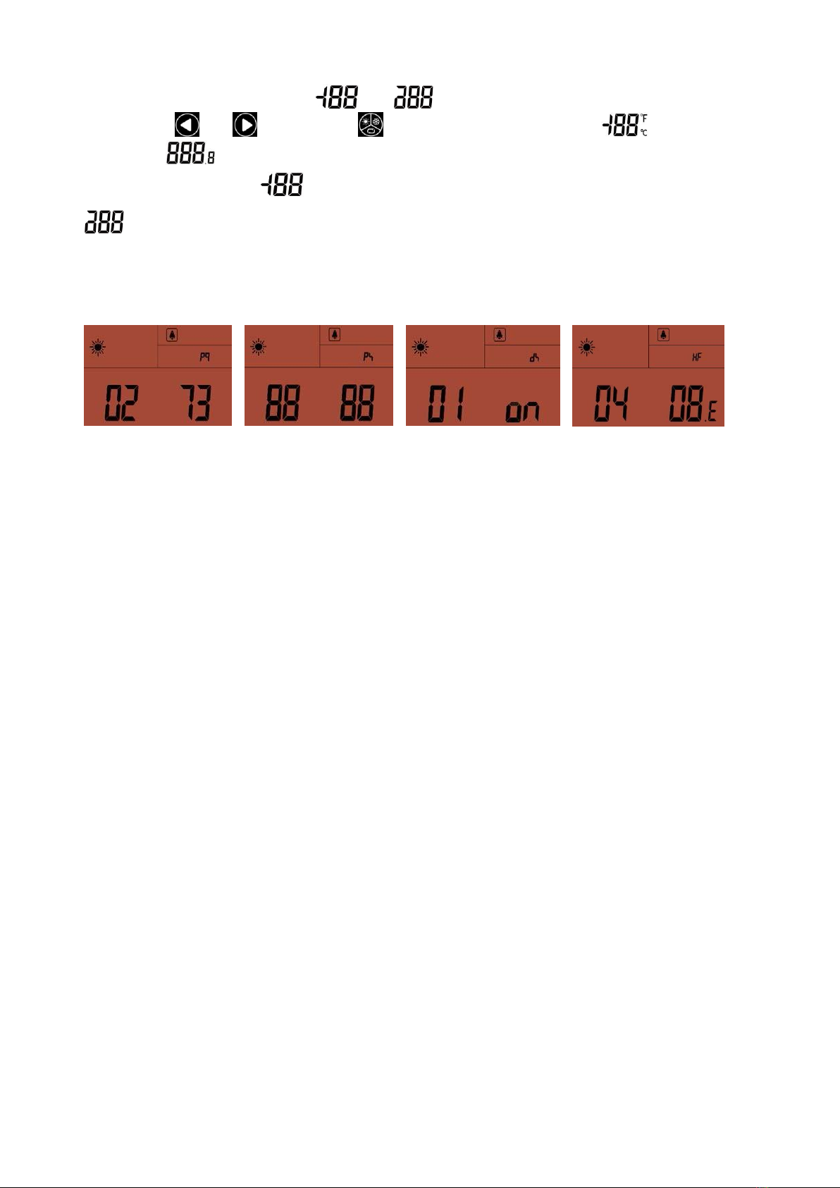
Display Instruction ................................................................................................................................12
Instruction for Function.........................................................................................................................13
Function Diagnosis ................................................................................................................................14
PARAMETER CHECKING AND ADUSTMENT ....................................................................................................15
Parameter list........................................................................................................................................15
Malfunctioning of the unit and maintenance.........................................................................................15
MAINTENANCE THE UNIT..............................................................................................................................18
Cleaning the pipe system in the heat exchanger ....................................................................................18
Cleaning the air system .........................................................................................................................18
Winter Shutdown/Lay-up ......................................................................................................................18
TROUBLESHOOTING......................................................................................................................................19
ENVIRONMENTAL INFORMATION ..................................................................................................................19
DISPOSAL REQUIREMENTS............................................................................................................................20
WIRING DIAGRAM ........................................................................................................................................21
Specification .................................................................................................................................................22
ENVIRONMENTAL INFORMATION...........................................................................................................23
DISPOSAL REQUIREMENTS ....................................................................................................................23
User Manual for APP.....................................................................................................................................27
READ THIS MANUAL CAREFULLY BEFORE STARTING UP THE UNIT. DO NOT THROW IT AWAY. KEEP
IT IN YOUR FILES FOR FUTURE REFERENCE.
BEFORE OPERATING THE UNIT, MAKE SURE THE INSTALLATION HAS BEEN CARRIED OUT
CORRECTLY BY A PROFESSIONAL DEALER. IF YOU FEEL UNSURE ABOUT OPERATION, CONTACT
YOUR DEALER FOR ADVICE AND INFORMATION.

2
INTRODUCTION
This manual
This manual includes the necessary information about the unit. Please read this manual carefully before
you use and maintain theunit.
The unit
The swimming pool heat pump is one of the most economical systems to heat the swimming pool
efficiently. Using the free renewable energy from the air and the earth it delivers up to five times more
energy in heating than a traditional heating system such as gas heater or electric element heater. So you
willsave 4/5cost of the traditional heating. The swimming pool heat pump lengthens your swimming
seasonand gives you comfort at a high level. You could enjoy swimming not only in summer, but also in the
spring, autumn and even through the winter season.
Ecological and economical heating
By making use of the renewable energy in the outside air, it consumes much less energy withlow
carbon emission. Use environment friendly advanced refrigerant R32 which has little to no effect on
Ozone.
Titanium heat exchanger
Advanced titanium heat exchanger ensures a long life span of heat pump free from corrosion and rust.
By using of titanium heat exchanger the heat pump could be applied with all types of water treatment
such as chlorine, mineral, bromine and salt water pools and spas.
Multiple functions
-Cooling and heating ,Auto functions available;
-Auto operation, Auto-restart, Auto defrost
-Timer on/off: no human attendance is required
- Wide ambient working condition: -15°C to46°C
Reliable operation
To guarantee the stable running and increase the sustainability of the unit multiple protection devices
have been built into pool heat pump which includes insufficient water flow protection,high/low
pressure protection, overload protection & compressor protection.
Safe use
The swimming pool heat pump works without oil, gas (petroleum) or other hazardous substance
which avoid potential risk that goes together. Moreover no gas (petroleum) connection or a fuel
tank is needed. No risk of intoxication, smell or pollution from leakage of such chemicals.
Self-diagnosis
When there is malfunction, the swimming pool heat pump will make self-diagnosis bydisplaying error
code from the control panel. The problem could be found out at a glance be referring to the
troubleshooting section of this manual.

3
SAFETY INSTRUCTIONS
Toprevent injury to the user, other people, or property damage, the following instructions mustbe
followed. Incorrect operation due to ignoring of instructions may cause harm or damage.
Install the unit only when it complies with local regulations, by-laws and standards. Check the main
voltage and frequency. This unit is only suitable for earthed sockets, connection voltage 220 –240 V ~ /
50Hz.
The following safety precautions should always be taken into account:
-Be sure to read the following WARNING before installing the unit.
-Be sure to observe the cautions specified here as they include important items related to safety.
-After reading these instructions, be sure to keep it in a handy place for future reference.
Do not install the unit yourself.
Incorrect installation could cause injury due to fire, electric shock, the unit falling or leakage of water.
Consult the dealer from whom you purchased the unit or a specializedinstaller.
Install the unit securely in a place.
When insufficiently installed, the unit could fall causing injury. When installing the unit in a small room,
please take measures (like sufficient ventilation) to prevent the asphyxia caused by the leakage of
refrigerant.
Use the specified electrical wires and attach the wires firmly to the terminal board (connection in such a
way that the stress of the wires is not applied to the sections).
Unit must be installed according to AS/NZS 3000:2018 wiring rules and the electrical connection must be
complete by a licensed electrician. Incorrect connection and fixing could cause afire.
Perform electrical work according to the installation manual and be sure to use a suitable circuit. If
the capacity of the power circuit is insufficient or there is an incomplete electrical circuit, it could result
in a fire or an electricshock and damage to the unit.
The unit must always have an earthed connection.
Never use an extension cable to connect the unit to the electric power supply.
Perform the installation securely and please refer to the installation instructions.
Incorrect installation could cause an injury due to possible fire, electric shocks, the unit falling, leakage of
water etc.
Do not move/repair the unit yourself.
Before proceeding with any maintenance, service or repair work, the product must be isolated from the
mains electrical supply. Only qualified personnel should carry out these tasks. Improper movement or
repair on the unit could lead to water leakage, electrical shock, injury or fire.

4
Do not install the unit in a place where there is a chance of flammable gas leaks.
If there is a gas leak and gas accumulates in the area surrounding the unit, it could cause an explosion.
Perform the drainage/piping work according to the installation instruction.
If there is a defect in the drainage/piping work, water could leak from the unit and household goods could
get wet and bedamaged.
Do not clean the unit when the power is ‘ON’.
Always shut ‘OFF’ the power when cleaning or servicing the unit. If not, it could cause an injury due to the
high speed running fan or an electricalshock.
Do not continue to run the unit when there is something wrong or there is a strange smell.
The power supply needs to be shut ‘OFF’ to stop the unit; otherwise this may cause an electrical shock or
fire.
Do not put your fingers or other items into the fan or evaporator.
The ventilator runs at high speed, it could cause seriousinjury.

5
ITEMS INSIDE PRODUCT BOX
Before starting the installation, please make sure that all parts are found inside the box.
The Unit Box
Item
Image
Quantity
Eco Full Inverter
Swimming pool heat
pump
1
Installation and
Operation Manual
1
Barrel Unions (40mm)
2
Winter Cover
1
Rubber foots for
anti-vibration
4
Water Drainage Pipe
1

6
OVERVIEW OF THE UNIT
Unit Dimension
\
MODEL
EFI 14
EFI 17
EFI 23
A
986
986
1076
B
668
668
720
C
366
366
442
D
405
405
456
E
608
608
628
F
106
106
116
G
380
380
330
H
189
189
219
I
123
123
158

7
Explode View
No.
Name
No.
Name
1
Top Cover
14
Reactance
2
Electric box cover
15
Bottom Panel component
3
Support frame
16
Inverter compressor
4
Electronic control components
17
High-pressure valve
5
Fin heat exchanger
18
Low-pressure switch
6
Left panel
19
Power waterproof cover
7
Motor bracket
20
Needle valve
8
DC fan motor
21
Controller
9
Middle panel
22
Four-way valve
10
Fan
23
Right panel
11
Front Panel
24
Titanium tube heat exchanger
12
Discharge grill
25
Electronic expansion valve
13
Reactance waterproof box

8
INSTALLATION
Installation information
The following information given here is not an instruction, but simply meant to give the user a better
understanding of the installation.
Condition of installation
The following information given here is not an instruction, but simply meant to give the user a better
understanding of the installation.
Installation place
Install the swimming pool heat pump on a flat, horizontal, and stable surface. Maintain 1 M of open space in
front of the discharge grids and 3 M on the outlet side of the ventilator. And reserve enough space to allow
access to temperature controller.
Make sure that the discharged air will not be breathed in.
To perfect your installation
--Avoid directing the flow of ventilated air towards a sensitive noise zone, such as room window.
--Avoid positioning pool heat pump on a surface that can transmit vibrations to dwelling.
--Try to avoid placing appliance under a tree or exposed to water or mud, which would be likelyto complicate
maintenance.
Water connection
The heat pump is connected to a filtration circuit with aby-pass.
It is imperative that the by-pass is placed after the pump and thefilter. The
by-pass generally consists of 3 valves.
This makes it possible to regulate the water flow which passes through the heat pump and to isolate the heat
pump completely for any maintenance work, without cutting the flow of filteredwater.

9
To channel condensation flows, we recommend that you install our condensate drain kit.
For this purpose the heat pump must be raised by at least 10 cm.
How to install the condensate drain kit?
1.
Install your heat pump by raising it by at least 10 cm using solid, moisture-resistant studs.
2.
Connect the exhaust hose to the drain hole located underneath the heat pump.
Hydraulic Connection
The filter must be cleaned regularly to ensure that the water in the system is clean and to avoid any
problems related to dirt or clogging of the filter.

10
Electrical connection
Electrical supply must correspond to that indicated on the appliance.
Unit must be earthed
Wiring must be completed by a licensed electrician
Set leakage protector according to local code
Connection cables have to be sized according to appliance power and installation requirements. Please
refer to below table:
Heat pump
Cable size
EFI 14
3x
2.
5mm
2/
AWG
14
EFI 17
3x
2.
5mm
2/
AWG
14
EFI 23
3x
4.
0mm
2/
AWG
12
The above wiring information is to be used as a guide only. Electrical connection must be made in accordance
with AS/NZS 3000:2018 wiring rules.
Use the cable glands and grommets provided inside the heat pump to routecables.
Trial running
If the length of your cable is more than 10 meters, we advise you to seek advice from a professional.
A voltage variation of ± 10% during operation is acceptable.
The power supply lines must be securely fastened.
The cable must be suitable for outdoor use.

11
After connecting water to the pool system, complete with a suitable by-pass and electrical connections by a
qualified electrician.
Be sure that:
1) Appliance is horizontal and on a firm base.
2) Water circuit is well connected (no leaks)
3) Electrical circuit is well connected (all cables tightened correctly at terminals and intermediate circuit
breaker), insulated and earthed correctly.
4) The installation requirements described previously are strictly adhered to.
ATTENTION: THE HEAT PUMP ONLY FUNCTIONS WHEN WATER FLOW IS PRESENT.
Then you can start up the heat pump following every point in the beloworder:
-Open by-pass valves
-Start pool system pump
-Turn on pool heat pump
-Set regulation
OPERATING THE UNIT
Operating the unit comes down to operating the digital controller.
ALWAYS ENSURE CONTROLLER IS DRY TO TOUCH.
NEVER PRESS THE BUTTONS OF THE DIGITAL CONTROLLER WITH A HARD, POINTED OBJECT.
THIS MAY DAMAGE THE DIGITAL CONTROLLER.
NEVER REMOVE OR SERVICE THE DIGITAL CONTROLLER YOURSELF, ASK A QUALIFIED SERVICE
PERSON TO DO THIS.

12
Controller Instruction
1. General
Input Voltage:DC12V
RS485
Communication
Short-Press for 1~5seconds,Long-Press for 5seconds.
No Button press for more than 30s,controller surface will exit to original normal.
User
can operate the controller only when the creen is lighton.
Back light of Screen is orange,characters and symbols areblack.
Operation temperature range for controller is -30~70℃。
2. Dial Set
On the back of controller board,there are 4 dials:
DP1
DP2
DP3
DP4
ON for beep sound
ON for sound whenwater
flow warning
ON for back light on
always
ON for self-diagonisestatus
OFF for no beep sound
OFF for no sound when
water flowwarning
OFF for back light onfor 30s
OFF for normal
3. Display and Operation Surface
Display Instruction
1. Instruction for Buttons
Start on/off:Short-press to turn.Also user can press this button to exit when they finish setting or checking
Running Modes:Short-Press to turn.Long-Press to into menu option
Increase:Tempreature set + or previous one
Decrease:Temperature set - or next one
Boost Running mode:Short-press to enter into
Smart Running mode:Short-press to enter into
Silent Running mode:Short-press to enter in

13
2. Intructions for Display Symbols
:Heating Pool mode
:Cooling Pool mode
:Auto run mode
:Boost run mode
:Smart run mode
:Silent run mode
:Heat Pump output capacity in actualtime
:wifi function
:Water in Temperature
:Water out Temperature
:Error Warning
3. Instruction for special display
When turn off the heat pump,screen only shows the last running symbol and data
shows 0. When heat pump has error warning,symbol displays and twinkles, water in area displays P
or
E, water out area displays Errorcode.
Instruction for Function
1.
Switch Modes
When heat pump is on,short-press to switch Heat/Cool/Auto,each mode is available for selecting
Boost/Smart/Silent threemodes.
2.
Set Temperature
When heat pump is on,short-press
or
into water temperature setting surface. Water in
area
temperature value twinkles,press
or
to select value,press to confirm and exit
current setting.No
any set up after 30 seconds,the controller will save the last setting and go back to original
surface.
3.
Set Parameter
When heat pump is on,Long-press into memu, displays Parameter Query,press
or
select
among Parameter Query/Parameter Setting/Debugging Status/History Fault.Short-press to
confirm your
selction and switch to ,press
or
select, displays the value.

14
When on status of Parameter Setting ,
and
display two“88”,it is asking you to enter your
password, press
and
to select, press to confirm.When password is right, displays
Parameter No. Displays related parameter value.
When on status of Debugging , displays the Number, 01 water pump debugging, 02 testing mode, and
displays ON or Off. The related mode symbol twinkles after entering into testing mode.
Display on each status:
Parameter Query Parameter Setting Debugging Status Error Query
Note:Value twinkles,means it is available for changing,or in verse
Function Diagnosis
When Heat Pump is off,Dial 4 switches to 1, give the heat pump power into status of function diagnosis
automatically.
Then dispaly will show each symbol and change every 1 second.

15
PARAMETER CHECKING AND ADUSTMENT
Parameter list
Some parameters can be checked and adjusted by the controller. Below is the parameterlist.
No.
Name
Instruction
1
Compressor running Frequency
Current hz
2
EEV Open degree
Current Value/5
3
Ambient Temperature
Current ℃
4
Outlet Water Temp.
Current ℃
5
Exhaust gas Temp.
Current ℃
6
Return gas Temp.
Current ℃
7
Coil Temp.
Current ℃
8
4-way Valve outlet Temp.
Current ℃
9
Water Circulaton Pump
0-off;1-on
10
4-way Valve Status
0-off;1-on
11
Standby
/
12
Standby
/
13
Standby
/
14
Standby
/
15
Standby
/
16
Running Current of Compressor
Current*10
17
Voltage
Current/10
18
Standby
/
19
Standby
/
20
Standby
/
21
Fan speed
Current/10
Malfunctioning of the unit and maintenance
When an error occurs or the protection mode is set automatically, the circuit board and thewired
controller will both display the errormessage.
Error
Meaning
Analysis
Diagnosis
Solution
P01
Water Flow failure
1.
No water flow;
2.
Flow switch failure;
3.
Water system block.
1.Check if water in valve is
closed or no
water in;
2.Check if flow switch is
blocked or
damaged;
3.Check if“Y”Shape filter
blocked.
1.
Open the valve;
2.
Change a new flowswitch
;
3.Clean or change a newfilter.
P02
High pressure
protection
1.Water flow is too small
2.
High-pressure switch is
damaged;
3.Refrigerant system block
;
4.EEV deadlock.
1.Check if water flow is not enough or
water pump flow is not enough;
2.Check if high-pressure switch is off;
3.Check if refrigerant system is blocked;
4.When heat pump is off and turn the
heat pump on and off to check if EEV
can be listenned by sound of reset.
1.Reinject water or change to a
new pump of larger water flow;
Change a new high-pressure switch;
3.Change a new filter;
4.Change a new EEV

16
P03
Low pressure
protection
1.Lack of gas;
2.Refrigerant system block
;
3.Exceed heat pump
operation range.
1.Check if gas system is leaking;
2.Check if filter is blocked;
3.Check ambient Temp. and water temp.
is over limitation.
1.Amend the leakage and
reinject the gas;
2.change a new filter.
P04
T3 Coil over heat
protection
1.Heat Pump fan blowing
area is blocked;
2.Evaporator is blocked;
3.T3 coil sensor position
was changed.
1.Check if the blowing area is open;
2.Check if the evaporator is blocked;
3.Check if the coil snesor resistance value
is correct.
1.Put away the blow area;
2.Clean the evaporator;
3.Change a new sensor.
P05
Exhausting gas
temperature
protection
1Lack of gas;
2.sensor position was
changed.
1.
Ceheck if refrigerant system is leaking;
2.
Check if the snesor resistance value is
correct.
1.Amend the leakage and reinject the
gas;
2.Change a new sensor.
P06
Outlet water
temperature
anti-freezing
protection
1.
lower water flow;
2.
heat exchanger
blocked;
3.
Y-shaped filter blocked
;
4.
Overlow load.
1.
check if air exists in water system;
2.
Plate heat exchanger if blocked;
3.
check if Y-shaped filter has block;
4.
check design of indoor water system if
reasonable,if have water bypass.
1.If drain valve has problem,change
a new one;
2.Blow plate heat exchanger with
water or high-pressure gas through
reverse direction;
3.Clean Y-shaped filter;
4.Water system must have bypass.
P07
Pipe
temperature
anti-freezing
protection
1.
sytem lack of gas;
2.
water sytem
has block;
3.
cooling system has
block.
1.
Check system if any leakage;
2.
Check Y-shaped filter has block;
3.
Check if cooling system filter has block.
1.Fix leakage and re-charge gas;
2.Clean Y-shaped filter;
2.Change filter.
P08
High-pressue 2
protection
High pressure switch 2
cuts
Check if high pressure switch 2 cuts
under unit OFF condition
Change high pressure switch 2
E01
Controller
communication
failure
Communication
cable cuts
Check communication cable if cut
Change connection cable or
re-connect
E02
TP1 exhaust gas
temperature
sensor failure
sensor temperature
deviation or
cuts
Check sensor resistance value or if
sensor cuts
Change sensor or re-connect
cable
E03
T3 coil
temperature
sensor failure
sensor temperature
deviation or cuts
Check sensor resistance value
or if
sensor cuts
Change sensor or re-connect
cable
E04
T4 ambient
temperature
sensor failure
Ensor temperature
deviation or cuts
Check sensor resistance value
or if
sensor cuts
Change sensor or re-connect
cable
E05
T5 liquid gas
temperature
sensor
sensor temperature
deviation or cuts
Check sensor resistance value
or if
sensor cuts
Change sensor or re-connect
cable
E06
TH return gas
temperature
sensor failure
sensor temperature
deviation or cuts
Check sensor resistance value
or if
sensor cuts
Change sensor or re-connect
cable
E07
TW water tank
temperature
sensor failure
sensor temperature
deviation or cuts
Check sensor resistance value
or if
sensor cuts
Change sensor or re-connect
cable
E08
T6 inlet water
temperature
sensor failure
sensor temperature
deviation or cuts
Check sensor resistance value
or if
sensor cuts
Change sensor or re-connect
cable
E09
T7 outlet water
temperature
sensor failure
sensor temperature
deviation or cuts
Check sensor resistance value
or if
sensor cuts
Change sensor or re-connect
cable
E10
Controller and
Drive PCB
Communicate
failure
Communication
cable cuts
Check communication cable if
cut
Change connection cable or
re-connect
This manual suits for next models
3
Table of contents
Popular Heat Pump manuals by other brands

Panasonic
Panasonic SXC09 3E5 Series installation manual

Haier
Haier HRG15 installation instructions

Panasonic
Panasonic WH-MDC09H3E5 quick guide

Solahart
Solahart ATMOS AIR 270 Operation & installation manual

Dimplex
Dimplex SI 22TU Installation and operating instructions

Dimplex
Dimplex LI 9AS Installation and operating instructions

Carrier
Carrier Performance 50VR-K installation instructions

York
York Ylha plus 12 installation manual

Rotex
Rotex RKHBRD011ADV17 RKHBRD014ADV17 RKHBRD016ADV17 installation manual

Nibe
Nibe F1345 Series Installer manual

Danfoss
Danfoss DHP-A user guide

Viessmann
Viessmann VITOCAL 350-A Installation and service instructions