Autocall TrueAlert ES A49SV-APPLW-O User manual

579-1237AC Rev. A
TrueAlert ES Addressable US/Weather Proof Wall Mount Speaker Notification Appliances
Installation Instructions
*05791237ACA*
Cautions, warnings, and regulatory information
Important: When the notification appliance emits light or sound, it indicates the possibility of an emergency situation that requires immediate atten-
tion of all occupants.
SAFETY: Always install, maintain, and test notification appliances within their specifications. Failure to follow all safety precautions and
instructions may result in loss of life and property due to non-functioning notification appliances. Some notification appliances use high
voltage. To avoid electrical hazards and avoid damage to appliances, make sure that the electrical power for the Notification Appliance
Circuit is disconnected at the control panel before installing, repairing, or internally adjusting any notification appliances. Even with
electrical power removed, some notification appliances (such as visible strobes) store a high voltage charge. The high voltage can cause
injury resulting in death from electrical shock. DO NOT TOUCH EXPOSED CIRCUITRY.
LOCATION REFERENCE: Location and quantity of appliances required must conform to the applicable local standards and guidelines
(the National Fire Alarm and Signaling Code (NFPA 72); ULC Standard CAN/ULC-S524, Installation of Fire Alarm Systems; the appropriate
model building codes, etc.) and specific requirements of the Local Authority Having Jurisdiction (AHJ). These notification appliances are
not intended for installation within hazardous locations as defined by the National Electrical Code (NEC) or NFPA.
Introduction
These appliances provide a speaker only (SO) or speaker/visible (S/V) warning of an alarm condition when activated from the control panel of a
compatible UL/ULC Listed, Autocall Fire Alarm System. Consult Autocall Fire Alarm panel documentation for compatibility information. The speakers
can be turned ON/OFF individually under compatible panel control.
Table 1: Products
Type Cover colors Models
Wall Mount
Speaker/Visible
(S/V) with cover
• Red
• White
Components:
A49SV-APPLW-O
A49SV-APPLW-O-BA
Covers:
A49SVC-WRFEU-O
A49SVC-WRFIRE-O
A49SVC-WRS-O
A49SVC-WWALT-O
A49SVC-WWBA-O
A49SVC-WWS-O
A49SVC-WWFIRE-O
A49SVC-WRBF-O
A49SVC-WRBC-O
A49SVC-WRBA-O
A49SVC-WRALT-O
A49SVC-WWBC-O
A49SVC-WWBF-O
A49SVC-WWFEU-O
Backplates:
A49MP-SVWR
A49MP-SVWW
Back boxes:
A49WPBB-SVWR
A49WPBB-SVWW
Wall Mount
Speaker Only
(SO) with cover
• Red
• White
Components:
A49SO-APPLW-O
A49SO-APPLW-O-BA
Covers:
A49SOC-WRFEU-O
A49SOC-WRBF-O
A49SOC-WRBC-O
A49SOC-WRBA-O
A49SOC-WWS-O
A49SOC-WWFIRE-O
A49SOC-WRBLANK-O
A49SOC-WRFIRE-O
A49SOC-WRS-O
A49SOC-WWBA-O
A49SOC-WWBC-O
A49SOC-WWBF-O
A49SOC-WWFEU-O
A49SOC-WWBLANK-O
A49SOC-WWALT-O
A49SOC-WRALT-O
Backplates:
A49MP-SOWR
A49MP-SOWW
Back boxes:
A49WPBB-SOWR
A49WPBB-SOWW
Kit contents: Appliance x1.
Number 8-1 inch thread forming screws x 4.
Not included:
Order a backplate separately for each appliance.
Order a back box, listed above, to mount the appliance assembly to the wall.
Order a cover, listed above, separately for each appliance.
Note: For information about TrueAlert ES appliance testing, see TrueAlert ES Addressable Appliances Testing and Application Guide (579-1049AC).
Strobe operation levels
The 49 S/V appliances have multiple strobe intensity levels. Levels W15, W75, W110, and W185 are rated for UL outdoor private mode applications.
Levels 15 and 75 are rated for UL indoor and uncontrolled wet Public Mode applications.
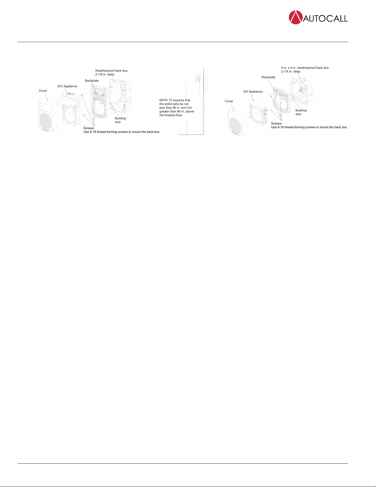
Back box mounting instructions
1. Select the mounting location and install the back box, see the back box installation instructions for more information.
2. Bring the building wiring through the rectangular opening in the backplate.
3. Connect the building wires to the backplate, see the wiring section.
4. Secure the backplate to the electrical box using the provided hardware. Install the backplate so that the contacts are above the opening for
the wiring.
5. Set the appliance settings. See Setting the address DIP switch.
page 2 579-1237AC Rev. A
TrueAlert ES Addressable US/Weather Proof Wall Mount Speaker Notification Appliances Installation
Instructions
6. To attach the cover to the appliance, carefully move the cover over the housing. Move the cover down over the housing and press it until it
snaps onto the housing.
7. Attach the assembled appliance to the backplate.
Figure 1: Back box mounting instructions
Unit removal or disassembly
1. Use a blade screwdriver to catch the latches on the left side of the cover, angling the head out from the appliance and then lifting. Repeat this
on each latch in turn, until the cover rotates away.
2. Insert a blade screwdriver into the gap between the housing and backplate at the bottom of the assembled appliance. Angle the head
towards the appliance and lift. When the housing moves toward you, lift and pull the appliance away with your hand.
Important: Ensure you do not compromise the gaskets when you disassemble the unit.
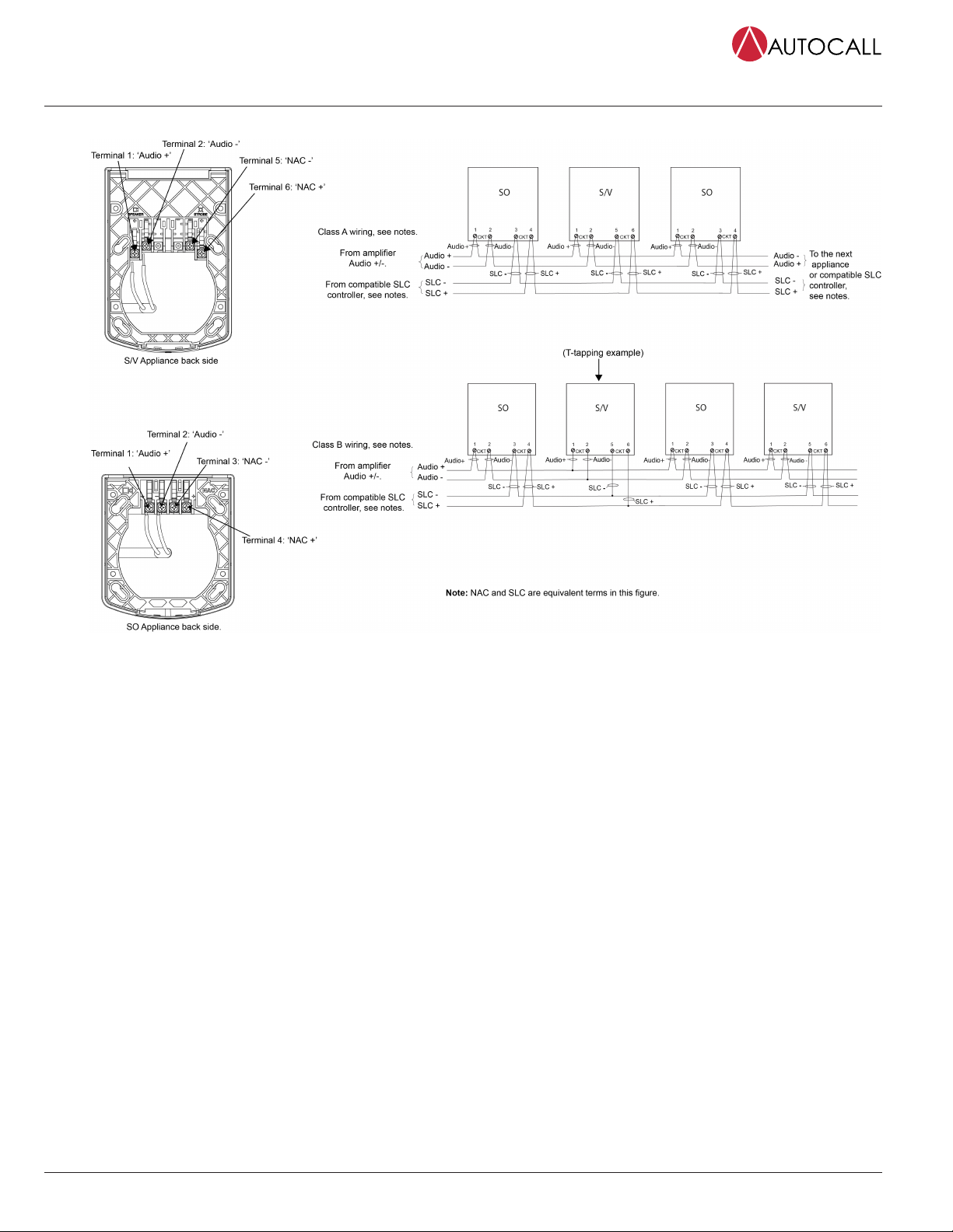
Wiring instructions
Warning: Make sure that all power is disconnected before starting the installation.
1. At the electrical box, connect the building wiring to the CKT + and CKT - terminals on the backplate.
2. To ensure proper continuity, use a torque wrench to tighten the terminal block screws to 12-15 inch-pounds.
3. Ensure that the correct polarity is maintained for each strobe unit.
4. SLC wiring must be twisted pair (TWP). CKT Terminals accept 2 Wires: 12-18 American wire gauge (AWG) TWP.
page 3 579-1237AC Rev. A
TrueAlert ES Addressable US/Weather Proof Wall Mount Speaker Notification Appliances Installation
Instructions
Important: Do not bring the conduit through the rear of the electrical box. Strip the lead insulation to 7/16 inch maximum.
Figure 2: Wiring instructions
Note: Wiring notes
a. Assign a maximum of 127 active appliances to a circuit. Assign a maximum of 63 active strobe appliances to a powered circuit.
The maximum wire resistance between appliances is 29 ohms. Refer to the field wiring diagrams of the driving compatible fire
alarm control panel for further instructions.
b. Notification appliances are rated using an individual module label.
c. Maintain the correct polarity on the terminal connections.
d. Terminals 1 through 6 each accommodate two wires, one wire going in and one wire going out to the next appliance.
e. These appliances are rated to the operating voltage limits of 23-30 VDC. The appliance can fail to operate as intended, and can
cause permanent damage to this equipment if it operates outside of these limits.
f. Only operate the TrueAlert IDNAC S/V and SO using a compatible power supply and amplifier.
g. T-tapping is not permitted for Class A wiring.
h. TrueAlert SLC wiring connections are supervised and power-limited.
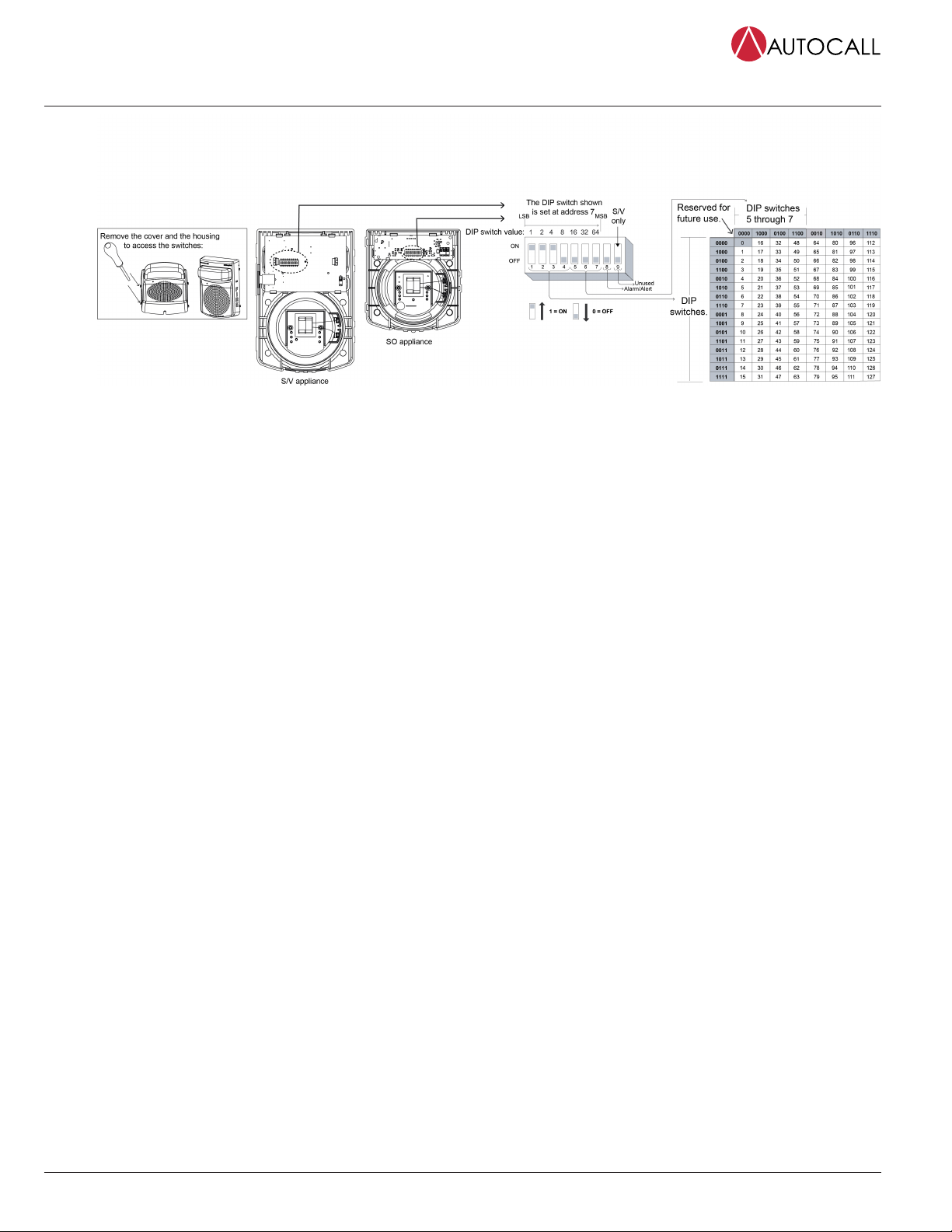
Setting the address DIP switch
Each addressable TrueAlert IDNAC notification appliance has a unique address that is set using an eight-position DIP switch (ADDR1). Assign up to 127
unique addresses an signaling line circuit (SLC), however, the total appliance loading available may be less due to appliance current requirements.
To set the address complete the following steps:
1. Complete the steps to disassemble the unit, see Unit removal or disassembly.
2. Use a non-metallic stylus, or the equivalent to set the switches.
3. Record the set address.
4. DIP switch position 8 determines whether this appliance is viewed by the system as an 'ALARM' (OFF) or 'ALERT' (ON) type of appliance.
Confirm the setting for the appliance at this address with the FACP system configuration documentation. DIP position 9 is not used (set to
OFF).
page 4 579-1237AC Rev. A
TrueAlert ES Addressable US/Weather Proof Wall Mount Speaker Notification Appliances Installation
Instructions
Figure 3: Setting the DIP switch address
Setting the strobe candela setting
1. The jumpers are factory set to FACP. Use this setting when programming the candela level at the 4100ES FACP. The candela setting is visible
through the slot on the side of the appliance.
2. For manual selection, remove the cover and slide the candela flag to the required setting. The candela setting is visible through the slot on
the side of the appliance. The settings are 15, W15,75, W75, W110, W185 candela, or FACP.
Note: To avoid a programming mismatch trouble, an authorized service personnel must program one of the 6 candela outputs for each
appliance. To set the candela through the Programmer, set it to FACP. For additional information refer to the ES Panel Programmer’s Manual
(574-849AC).

page 5 579-1237AC Rev. A
TrueAlert ES Addressable US/Weather Proof Wall Mount Speaker Notification Appliances Installation
Instructions
Audio circuit configuration for S/V and SO appliances
Move the wire harness position to the correct terminal post for audio circuit voltage and power tap selection. See Figure 4 and Table 4.
Figure 4: Setting the strobe and appliance configuration
Appliance specifications
Table 2: Environmental specifications
Specification Rating
Rated DC Control/Strobe Voltage Range SPECIAL APPLICATION 23-30 VDC
UL/ULC temperature rating Outdoor private: -40 °F to 150.8 °F (-40°C to 66°C)
Indoor and uncontrolled wet Public Mode: 32 °F to 122 °F (0°C to 50°C)
FM temperature rating -40 °F to 120 °F (-40°C to 49°C)
UL/ULC humidity range 95%, non-condensing at140 °F (60°C)
Connections Terminal for 18AWG to 12AWG
(0.82mm2 to 3.31mm2)
CAUTION: The appliance enclosures are available in red and white. Do not paint or otherwise alter the factory finishes in any way.
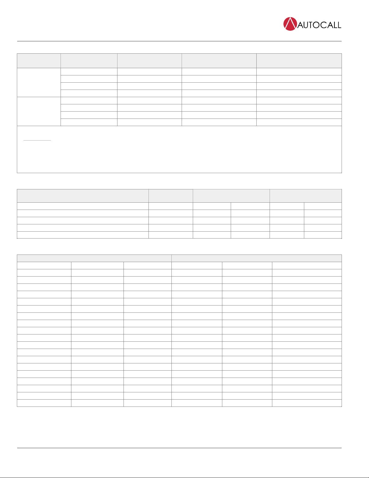
Table 3: Maximum RMS operating current
Candela selection Appliance type 23V*
(CD4) 15cd S/V 47 mA
(CD3) WP15 cd S/V 81 mA
(CD2) 75 cd S/V 100 mA
(CD1) WP75 cd S/V 187 mA
(CD6) WP110 cd S/V 230 mA
(CD7) WP185 cd S/V 298 mA
Speaker Only SO 15 mA
* For connection to IIDNAC SLCs
Table 4: Wall speaker specifications
Specification Rating
Input Voltage 25VRMS or 70.7 VRMS - Speakers are for connection to compatible fire
alarm audio circuits.
Power Taps via Jumper J1 1/4 W, 1/2 W, 1 W and 2 W
Frequency Response Fire Alarm 400Hz to 4000 Hz
579-1237AC Rev. A
© 2018 Johnson Controls. All rights reserved. All specifications and other information shown were current as of document revision and are subject to change without notice. Additional listings may be applicable, contact your local Autocall
product supplier for the latest status. Listings and approvals under Tyco Fire & Security GmbH, and the product names listed in this material are marks and/or registered marks. Unauthorized use is strictly prohibited. NFPA 72 and National
Fire Alarm Code are registered trademarks of the National Fire Protection Association (NFPA).
Table 5: TrueAlert Addressable Wall Mount S/V and SO Units - speaker jumper setting and output ratings (25 V or 70 V audio)
Voltage Jumper J1 to Tap Tap setting in Watts UL1480 reverberant at 10ft
SV/SO models
ULC-S541 anechoic at 3m
SV/SO models
E 1/4 78 80
F 1/2 81 83
G 1 84 86*
25V
H 2 87 89*
A 1/4 76 79
B 1/2 80 83
C 1 84 86*
70.7 V
D 2 87 89*
Note:
•Reverberant dBA measurements are a minimum UL rating based on sound level measurements made in UL’s reverberant test chamber.
• Anechoic dBA measurements are a minimum ULC rating based on sound pressure level measurements made in ULC’s anechoic test chamber.
• The sound pressure level decreases by 3 dB at an angular displacement of 25° from the line perpendicular to the speaker’s center. The SPL
decreases by 6dB at an angle of 35° from that line.
* Only marked settings may be used for ULC fire alarm applications.
Table 6: Outdoor private mode Candela (CD) rating for W15/W75/W110/W185
Straight out from
unit Vertical below unit Left/right horizontal
Candela 0° 45° 90° 45° 90°
WP15 Typical CD at 77 °F (25 °C) 69 25 18 32 12
WP75 Typical CD at 77 °F (25 °C) 240 100 60 119 47
WP110 Typical CD at 77 °F (25 °C) 300 118 74 160 58
WP185 Typical CD at 77°F (25°C) 445 169 105 228 75
Table 7: Percent of rated light output at 15 and 75 candela setting (Public Mode - room temperature)
Vertical dispersion Horizontal dispersion
Y-Plane Angle UL Req Output Typical Output X-Plane Angle UL Req Output Typical Output
0 100% 194% 0 100% 194%
5 90% 192% ±5 90% 203%
10 90% 132% ±10 90% 168%
15 90% 129% ±15 90% 155%
20 90% 145% ±20 90% 166%
25 90% 150% ±25 90% 169%
30 90% 112% ±30 75% 164%
35 65% 124% ±35 75% 151%
40 46% 114% ±40 75% 145%
45 34% 90% ±45 75% 121%
50 27% 91% ±50 55% 97%
55 22% 78% ±55 45% 83%
60 18% 72% ±60 40% 79%
65 16% 68% ±65 35% 70%
70 15% 75% ±70 35% 59%
75 13% 74% ±75 30% 50%
80 12% 68% ±80 30% 51%
85 12% 63% ±85 25% 45%
90 12% 45% ±90 25% 41%
This manual suits for next models
3
Table of contents
Other Autocall Speakers manuals


 instructions")

