Autojack Mig Master MIG130 Installation manual

SAFETY AND OPERATING MANUAL
Mig Master Welder
MIG130
ORIGINAL INSTRUCTIONS

2
MIG130
Welcome to Autojack!
Dear Customer, Congratulations on your purchase.
Before using this product for the first time, please be sure to
read these instructions for use.
They provide you with all the information necessary for using
the product safely and to ensure its long service life.
Closely observe all safety information in these instructions!
General Power Tool Safety Warnings 3
Symbol Chart 8
Technical Specification/Package Contents 9
Assembly 10
Operation 13
Maintenance/Troubleshooting 15
Autojack Guarantee 16
Declaration of Conformity 19
Machine Schematic 20
TABLE OF CONTENTS

3
MIG130
WARNING, please read all safety
warnings and instructions.
Failure to follow the warnings and instructions
may result in electric shock, fire and/or serious
injury.
Save all warnings and instructions for
future reference.
The term “Power tool” in the warnings refers to
your electric (corded) power tool or battery-
operated (cordless) power tool.
1. Work area safety
a) Keep work area clean and well lit.
Cluttered or dark areas invite accidents.
b) Do not operate power tools in explosive
atmospheres, such as in the presence of
flammable liquids, gases or dust. Power tools
create sparks which may ignire the dust or
fumes.
c) Keep children and bystanders away while
operating a power tool. Distractions can cause
you to lose control.
2. Electrical safety
a) Power tool plugs must match the outlet.
Never modify the plug in any way.
Do not use any adaptor plugs with grounded
power tools. Unmodified plugs and matching
outlets will reduce risk of electric shock.
b} Avoid body contact with grounded surfaces,
such as pipes, radiators, ranges and
refridgerators. There is an increased risk of
electric shock if your body is grounded.
c) Do not expose power tools to rain or wet
conditions. Water entering a power tool will
increase the risk of electric shock.
GENERAL POWER TOOL SAFETY WARNINGS
d) Do not abuse the cord. Never use the cord for
carrying, pulling or unplugging the power tool.
Keep cord away from heat, oil, sharp edges or
moving parts. Damaged or entangled cords
increase the risk of electric shock.
e) When operating a power tool outdoors, use an
extension cord suitable for outdoor use. Use of a
cord suitable for outdoor use reduces the risk of
electric shock.
f) If operating a power tool in a damp location is
unavoidable, use a residual current device (RCD)
protected supply. Use of an RCD reduces the risk
of electric shock.
3. Personal safety
a) Stay alert, watch what you are doing and use
common sense when operating a power tool. Do
not use a power tool while you are tired or under
the influence of drugs, alcohol or medication. A
moment of inattention while operating power
tools may result in serious personal injury.
b) Use personal protective equipment. Always
wear eye protection. Protective equipment such
as dust mask, non-skid safety shoes, hard hat, or
hearing protection used for appropriate conditions
will reduce personal injuries.
c) Prevent unintentional starting. Ensure the
switch is in the off position before connecting to
power source and/or battery pack, picking up or
carrying the tool. Carrying power tools with your
finger on the switch or energizing power tools that
have the switch on invites accidents.
d) Remove any adjusting key or wrench before
turning the power tool on. A wrench or a key left
attached to a rotating part of the power tool may
result in personal injury.

4
MIG130
e) Do not overreach. Keep proper footing and
balance at all times. This enables better
control of the power tool in unexpected
situations.
f) Dress properly. Do not wear loose clothing
or jewellery. Keep your hair, clothing and
gloves away from moving parts. Loose
clothes, jewellery or long hair can be caught in
moving parts.
g) If devices are provided for the connection
of dust extraction and collection facilities,
ensure these are connected and properly
used. Use of dust collection can reduce dust-
related hazards.
4. Power tool use and care
a) Do not force the power tool. Use the correct
power tool for your application. The correct
power tool will do the job better and safer at
the rate for which it was designed.
b) Do not use the power tool if the switch
does not turn it on and off. Any power tool
that cannot be controlled with the switch is
dangerous and must be repaired.
c) Disconnect the plug from the power
source and/or the battery pack from the
power tool before making any adjustments,
changing accessories, or storing power tools.
Such preventive safety measures reduce the
risk of starting the power tool accidentally.
d) Store idle power tools out of the reach of
children and do not allow persons
unfamiliar with the power tool or these
instructions to operate the power tool.
Power tools are dangerous in the hands of
untrained users.
GENERAL POWER TOOL SAFETY WARNINGS
e) Maintain power tools. Check for
misalignment or binding of moving
parts, breakage of parts and any other
condition that may affect the power
tool’s operation. If damaged, have the
power tool repaired before use. Many
accidents are caused by poorly
maintained power tools.
f) Keep cutting tools sharp and clean.
Properly maintained cutting tools with
sharp cutting edges are less likely to
bind and are easier
g) Use the power tool, accessories and
tool bits etc. in accordance with these
instructions, taking into account the
working conditions and the work to be
performed. Use of the power tool for
operations different from those
intended could result in a hazardous
situation.
5. Service
a) Have your power tool serviced by a
qualified repair person using only
identical replacement parts. This will
ensure that the safety of the power tool
is maintained.
b) If the replacement of the
supply cord is necessary, this has
to be done by the manufacturer
or its agent in order to avoid a
safety hazard.
Use power tools only with specifically
designated battery packs. Use of any other
battery packs may create a risk of injury or fire

5
MIG130
7
Additional Safety
Instructions for welders
Welders have many sources of danger. It
is therefore particularly important for the
welder to comply with the following rules
so as not to place themselves or others in
danger and to avoid endangering people
and equipment.
a)
Have all work on the mains voltage
system, for example on cables, plugs,
sockets, etc., performed only by trained
electricians. This particularly applies to
configuring intermediate cables.
b)
If an accident occurs, disconnect the
welding power source from the mains
immediately.
c)
If electric touch voltages occur, switch
off the welding set immediately and have
it checked by an expert.
d)
Always check for good electrical
contacts on the welding current side.
GENERAL POWER TOOL SAFETY WARNINGS
e) Wear insulating gloves on both hands for
welding. These offer protection from electric
shocks (idling voltage in the welding circuit),
harmful radiation (Heat and UV radiation) and
from glowing metal and slag spatter.
f) Wear firm, insulated footwear. Your
shoes should also protect you in wet
conditions. Open- toed footwear is not
suitable since falling droplets of glowing
metal will cause burns.
g) Wear suitable clothing, do not wear
synthetic clothes.
h) Do not look into the arc with
unprotected eyes, use only a welding
safety shield with the proper safety glass in
compliance with DIN standards. In addition
to light and heat, which may cause dazzling
and burns, the arc also gives off UV
radiation. Without proper protection, this
invisible ultraviolet radiation causes very
painful conjunctivitis, which will only be
noticeable several hours later. In addition,
UV radiation will cause sunburn-type
symptoms on unprotected parts of the
body.
i) Personnel or assistants in the vicinity of
the arc must also be notified of the
dangers and provided with the required
protection; if necessary install safety walls.
j) Ensure adequate ventilation for
welding, particularly in small rooms
since the process causes smoke and
harmful gases.
k) Do not carry out any welding work on
tanks that have been used to store gases,
fuels, mineral oil or the like, even if they
have been empty for a lengthy period of
time, since any residue will result in a
danger of explosion.

6
MIG130
l) Special regulations apply in areas where
there is a potential risk of fire and/or
explosion.
m) Welds that are exposed to large stresses
and must comply with safety requirements
may only be completed by specially trained
and approved welders. Examples of such
welds include pressure vessels, rails, trailer
hitches, etc.
n) It must be noted that the protective
conductor in electrical systems of
appliances may be destroyed by the
welding current in the event of negligence,
for example if the earth terminal is placed
on the welding set casing to which the
protective conductor of the electrical
system is connected. The welding work is
completed on a machine with a protective
conductor connection. It is therefore
possible to weld on the machine without
having connected the earth terminal to it.
In this case the welding current will flow
from the earth terminal through the
protective conductor to the machine. The
high welding current may cause the
protective conductor to melt.
o) The fuses on the supply cables to the
mains sockets must comply with the
relevant regulations (VDE 0100). To
comply with these regulations, only fuses
or circuit breakers suitable for the cross-
section of the cables may be used (for
earthing contact sockets max. 16 A fuses or
16 A circuit breakers). The use of too high
a fuse may result in the cable burning and
fire damage to the building.
GENERAL POWER TOOL SAFETY WARNINGS
8. Additional Safety Instructions for
Constricted and wet areas
When working in constricted, wet or
hot areas, use insulating supports and
intermediate layers as well as slip-on
gloves made of leather or other non-
conductive materials to insulate your
body against the floor, walls,
conductive parts of the machine and
the like.
If you use small welding transformers
for welding in places with an increase
electrical risk, for example in
constricted areas with conductive
walls, (tanks, pipes, etc.), in wet areas
(which make work clothes wet) and in
hot areas (perspiration on work
clothes), the output voltage of the
welding set when idling must not
exceed 48 V (effective value).
Therefore, the appliance may not be
used for these purposes because its
output voltage is higher than this.

7
MIG130
9. Additional Safety Instructions for safety
clothing
a) While working, the welder must protect his
entire body from radiation and burns by wearing
suitable clothing and a face guard.
b) Slip-on gloves made of a suitable material
(leather) must be worn on both hands. They must
be in perfect condition.
c) Suitable aprons must be worn to protect
clothing from sparks and burns. A safety suit and if
necessary, head protection must be worn if
required by the type of work in question, e.g.
overhead welding.
d) The safety clothing used as well as all
accessories must comply with the “Personal Safety
Equipment” directive.
10. Additional Safety Instructions for
Protection from radiation and burns.
a) Provide information about the risk to eyes at
the working site in the form of a poster with the
wording “Caution – do not look at the flames”.
Workplaces are to be screened off wherever
possible so that personnel in the vicinity are
protected. Unauthorized persons are to be kept
away from the welding work.
b) The walls in the immediate vicinity of
stationary workplaces should not have a light
color or a sheen. Windows up to head height are
to be protected against radiation passing
through them or reflecting off them, for example
by coating them with a suitable paint.
Do not store or use the equipment in wet
conditions or in the rain. Use the equipment only
indoors.
GENERAL POWER TOOL SAFETY WARNINGS
11. Using an Extension Cable.
a)
If an extension cable is required, use an
approved triple core extension cable
suitable for the power input of the tool.
b)
Grounded tools always require a three
wire extension cable.
c)
As the distance from the supply outlet
increases you must use a heavier gauge
extension cable. Using extension cables with
inadequately sized wire causes a serious drop
in voltage, resulting in loss of power and
possible tool damage.
d)
The smaller the gauge number of the wire
the greater the capacity of the cord.
e)
When using a cable reel, always unwind
the cable completely.

8
MIG130
SYMBOL CHART

9
MIG130
SPECIFICATION
MIG130
Mains Voltage
230V
Rated Max Supply Current
16 A
No-load Voltage
30 V
Input Power
3.91 KVA
Output Amperage @ Duty Cycle
60 A @ 60%
120 A @ 10%
Suitable Size Flux Cored Wire
0.6 –1.0 mm
Efficiency
85%
Insulation Class
H
Enclosure Protection
IP21S
Cooling Type
Fan
Weight
17 KG
Dimensions
465x235x398 mm
Package Contents
MIG130 Welder
1.8Mtr MIG Torch
1.2Mtr 200A Earth Clamp
Brush
Mask
Wire Spool
TECHNICAL SPECIFICATION
Intended Use
The flux cored welding set is designed for self-shielding flux cored welding using suitable wire.
The additional application of gas is not required.
The equipment is to be used only for its prescribed purpose. Any other use is deemed to be a
case of misuse. The user / operator and not the manufacturer will be liable for any damage or
injuries of any kind caused as a result of this.
Please note that our equipment has not been designed for use in commercial, trade or
industrial applications. Our warranty will be voided if the equipment is used in commercial,
trade or industrial businesses or for equivalent purposes.
10
MIG130
ASSEMBLY
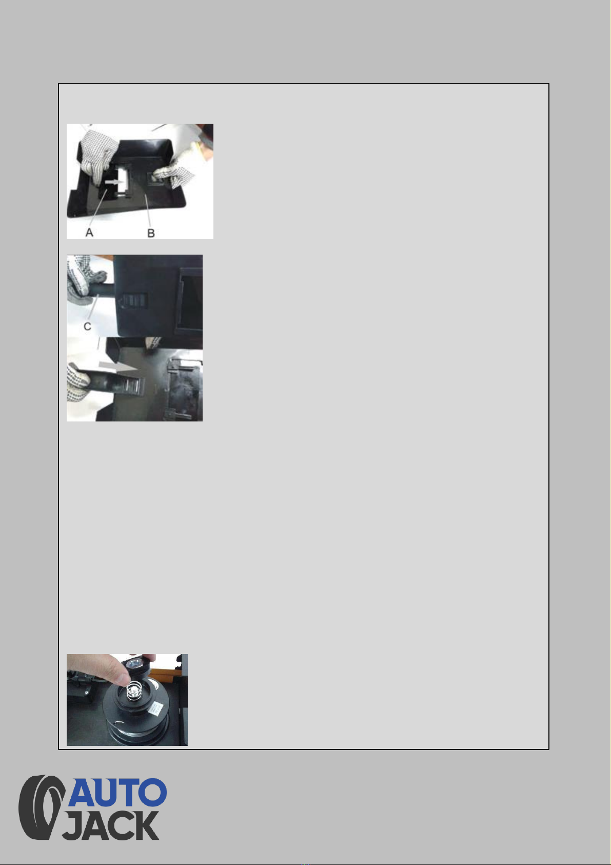
1.Fitting the welding screen
1.
Place the welding glass (A) over the frame for welding screen(B).
2.
Insert the handle welding mask hole.
2.Fitting the wire spool
1
Wire types
Various welding wires are required for different applications. The welding set can be used
with welding wires with a diameter of 0.9 mm. The appropriate feed rollers and contact
tubes are supplied with the set. The feed roller, contact tube and wire cross-section must
always match each other.
2
Wire spool capacity
Wire spools with a maximum weight of 0.45 kg can be fitted in the welding set.
3 Inserting the wire spool
1.
Unlock the housing cover by turning the fastening screw through 90° and flip open the
cover.
2.
Check that the windings on the spool do not overlap so as to ensure that the wire can
be unwound evenly.
3.
Place the wire spool on the spool holder. Ensure that the end of the welding wire is
unwound on the side of the wire guide, see arrow.

11
MIG130
4 Inserting the welding wire and adjusting the wire guide
1.
Pull the pressure roller spring and swing it upward.
2.
Pull the pressure roller holder(E) downwards.
3.
Swing the screws (F) 90 °and pull off upwards.
4.
Check the feed roller (G). The appropriate wire thickness must be specified on the top of
the feed roller (G). The feed roller (G) is fitted with two guide grooves. Turn the feed roller
(G) over if necessary or replace it.
5.
Position the feed roller holder (G) again and secure it.
6.
Remove the gas nozzle (10) from the torch (11) by turning it clockwise, unscrew the contact
tube (15). Place the hose package (9) on the floor as straight as possible pointing away from
the welding set. (See page 8)
7.
Cut off the first 10 cm of the welding wire to produce a straight cut with no shoulders,
warping or dirt. Deburr the end of the welding wire.
ASSEMBLY

12
MIG130
ASSEMBLY
8.Push the welding wire through the guide tube
(C) between the pressure and feed rollers (G) into the hose package mounting (H).
Carefully push the welding wire by hand into the hose package until it projects out of the
hose package by approx. 1 cm at the torch (11).
9.
Push the pressure roller holder(E) upwards and Pull the pressure roller spring(D) and
swing it downward.
10.
Screw the appropriate contact tube (15) for the welding wire diameter on to the torch
(Fig. 11) and fit the gas nozzle (10), turning it clockwise.
11.
Set the adjusting screw for the roller brake (I) so that the wire can still be moved and the
roller stops automatically after the wire guide has been braked.

13
MIG130
At this point, you are ready to begin welding.
Turn the welder on and ensure that your
workpiece is clean of rust or dirt and attach the
clamp to it. Make sure that the gas regulator is
attached to your bottle if necessary and turn it
anti-clockwise to meet the demands of your weld
whilst pressing the torch trigger. The current will
need to be adjusted as you are welding to find
the correct variables to match your wire feed
speed.
OPERATION
To begin welding, you must first connect your welder up to a 230V supply using the
plug provided and plug the torch in to the torch connection on front panel. The first
image below shows where the input is for the mains supply.
Next, you will need to install the welding wire if applicable, to do this, you must lift
the side panel and locate the wire feed motor. The wire size needed will depend on
your workpiece but you will need the corresponding roller and tips for the wire size
fitted, e.g. a 1mm roller, lining and tips will be used with 1mm wire. To fit the wire,
you put the wire feed reel on the hub of the motor and tighten it accordingly. Once
this has been done, you can push the wire through the rollers and then the lining,
ensuring it is not too tight (if the wire is too tight between the rollers it can snag and
stop feeding/cause too much resistance on the motor) and press the trigger on the
torch for it to start feeding. The wire should be fed through until it comes through
the nozzle by a few cm. Then the correct size tip can be screwed onto the nozzle.
The above listed techniques are both adequate for welding depending on your workpiece.
The image to the right shows a few
types of welding techniques that are
administered when MIG welding.
The pushing weld is when the torch is
angled against the direction of the
weld.
The pulling weld is when your torch is
angled towards the direction of the
weld.

14
MIG130
Setting
Since the welding set must be set to suit the specific application, we
recommend that the settings be made on the basis of a test weld.
Setting the welding current
The welding current can be set to 2 different levels using the welding current
adjustment switch (6). The required welding current depends on the material
thickness, the required penetration depth and the welding wire diameter.
Setting the wire feed speed
The wire feed speed is automatically adjusted to the current setting. The final
wire feed speed setting can be made on the welding wire speed controller (5). It
is advisable to start with the medium setting and to re-adjust the speed as
necessary. The required quantity of wire depends on the material thickness, the
penetration depth, the welding wire diameter and also the size of the gap to be
bridged between the workpieces you wish to weld.
OPERATION

15
MIG130
MAINTENANCE
The following points will aid with keeping your welder in good condition to
ensure peak performance:
Make sure that torch consumables are checked and replaced regularly
Keep the welder in a dry place when not in use
Check that the earth clamp can clamp sufficiently, replace if necessary
Make sure all cables are in good condition with no nicks or
degradation to the sheathing
Regularly clear metallic dust from inside of the machine (use a low-
pressure air gun)
Check all connections are usable with no oxidization or wear
Number
Fault
Failure cause
Troubleshooting
1
Overheat Light
Poor ventilation of
power supply leads to
overheating protection
Improve ventilation
Excessive ambient
temperature
Automatic recovery after
temperature drop
Exceeded rated duty
cycle
Automatic recovery after
temperature drop
2
Motor fan not
working or is
slower than usual
Faulty power switch
Replace switch
Faulty fan
Replace fan
Wire broken
Check wires
3
Wire feed motor
not working
Potentiometer (knob)
broken
Replace potentiometer
(knob)
Nozzle blocked
Change nozzle
Rollers too loose
Tighten rollers
4
No pilot arc
Earth cable faulty
Change earth cable
Earth clamped on
dirty/rusty metal
Connect to clean
workpiece
5
Arc unstable
Incorrect tips
Change to correct tip
Power cable too thin
Use thicker power cable
Wire feed resistance
too large
Clean/replace the liner or
torch cable
TROUBLESHOOTING

16
MIG130
AUTOJACK GUARANTEE
1.
Guarantee
1.1
Autojack guarantees that for a period
of 12 months from the date of purchase
the components of qualifying products
(see clauses
1.2.1 to 1.2.8) will be free from defects
caused by faulty construction or
manufacture
1.2
During this period, Autojack, will
repair or replace free of charge any
parts which are proved to be faulty in
accordance with paragraph 1.1
providing that:
1.2.1
You follow the claims procedure set
out in clause 2.
1.2.2
Autojack and its Authorised
Dealers are given reasonable
opportunity after receiving notice of
the claim to examine the product.
1.2.3
If asked to do so by Autojack or its
Authorised Dealer, you return the product
at your own cost to Autojack’s or the
supplying Authorised Dealer’s Premises,
For the examination to take place clearly
stating the Returns Material Authorisation
Number given by Autojack or an Authorised
Dealer.
1.2.4
The fault in question is not caused by
industrial use, accidental damage, fair
wear and tear, wilful damage, neglect,
incorrect electrical connection, misuse,
alteration or repair of the product without
approval.
1.2.5
The product has been used
in a domestic environment only.
1.2.6
The fault does not relate to
consumable items such as blades,
bearings, drive belts orother wearing
parts which can reasonably be
expected to wear at different rates
depending on usage.
1.2.7
The product has not been
used for hire purposes.
1.2.8
The product has been
purchased by you, as the guarantee
is not transferable from a private
sale.

17
MIG130
AUTOJACK GUARANTEE
2.
Claims Procedure
2.1
In the first instance please
contact the Authorised Dealer who
supplied the product to you. In our
experience many initial problems
with machines that are thought to be
fault due to faulty parts are actually
solved by correct setting up or
adjustment of the machine. A good
Authorised Dealer should be able to
resolve the majority of these issues
much more quickly than processing a
claim under the guarantee. If a return
is requested by the Authorised Dealer
or Autojack, you will be provided with
a Returns Material Authorisation
Number which must be clearly stated
on the returned package, and any
accompanying correspondence.
Failure to provide a Returns Material
Authorisation Number may result in
item being refused delivery.
2.2
Any issues with the product
resulting in a potential claim under
the guarantee must be reported to
the Authorised Dealer from which it
was purchased within 48 hours of
receipt
1.3
If the authorized Dealer who
supplied the product to you has been
unable to satisfy your query, any
claims made under this guarantee
should be made in a letter setting out
the date and place of purchase, giving
a brief explanation of the problem
which has lef to the claim. This letter
should be then sent with proof of
purchase to Autojack. If you include a
contact number with this it will speed
your claim up.
1.4
Please note that it is essential
that the letter of claim reaches
Autojack on the last day of this
guarantee at the latest. Late claims
will not be considered.

18
MIG130
AUTOJACK GUARANTEE
3.
Limitation of Liability
3.1
We only support products for
domestic and private use. You agree
not to use the product for any
commercial, business or resale
purposes and we have no liability to
you for any loss of profit, loss of
business, business interruption or
loss of business opportunity.
3.2
This guarantee does not confer
any rights other than these expressly
set out avoice and does not cover any
claims for consequential loss or
damage. This guarantee is offered as
an extra benefit and does not affect
your statutory rights as a consumer.
4. Notice
This guarantee applies to all product
purchased from an Authorised Dealer of
Autojack within the United Kingdom. Terms
of guarantee may vary in other countries.

19
MIG130
DECLARATION OF CONFORMITY
CE DECLARATION OF CONFORMITY
Toolsave
Unit C, Manders Ind Est.,
Old Heath Road, Wolverhampton,
WV1 2RP.
Declares that the Mig Master MIG130 Welder
is in compliance with the regulations included in theDirectives:
2006/42/EC
EC DECLARATION OF CONFORMITY
Certificate for EC-type examination delivered
by AV Technology Ltd. Unit 2 Easter Court,
Europa Boulevard, Warrington, Cheshire,
WA5 7ZB
(Certificate No.: GB/1067/5862/16)
Person who declares: Bill Evans
27/08/2020
The Director

20
MIG130
1. Power Cable 11.Wire Spool 21.Overheat LED
2. Earth Clamp 12.Handle 22.Wire Speed Knob
3. Welding Torch 13.Latch 23.Current Adjust Knob
4. Front Panel 14.Top Cover 24.Power Switch
5. Base Panel 15.Transformer 25.Roller and Tips Holder
6. Control PCB 16.Rear Panel
7. PCB Holder 17.Cooling Fan
8. Middle Panel 18.Foot
9. Wire Feeder 19.Right Side Panel
10.Left Side Panel 20.Potentiometer
MACHINE SCHEMATIC
Table of contents
Other Autojack Welding System manuals


Popular Welding System manuals by other brands

Lincoln Electric
Lincoln Electric ACTIVE8 Operator's manual

Everlast
Everlast Cyclone 262 Use guide

MAGNAWELD
MAGNAWELD RS 200 MK user manual

RINCO ULTRASONICS AG
RINCO ULTRASONICS AG Standard 3000 operating instructions

Xcel-Arc
Xcel-Arc RazorWeld Razor TIG320 ACDC operating manual

Lincoln Electric
Lincoln Electric PRECISION TIG 275 IM702-A Operator's manual


 Operator's manual")
Lincoln Electric
Lincoln Electric RANGER 250 GXT (AU) Operator's manual

Lincoln Electric
Lincoln Electric liquidarc Maxmig 330R operating manual

Sealey
Sealey SUPERMIG255.V2 instructions

ENEL
ENEL 150A user manual

Snap-On
Snap-On MIG220 owner's manual

Buffalo Tools
Buffalo Tools HIT140 Assembly & operating instructions