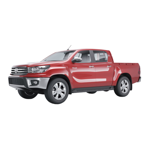
Avia D60 User manual

DEARDRIVER,
ThisManualshouldacquaintyou withthecorrectoperation and routine
maintenance ofyournewvehicleAVIA.
Italsoprovidestheimportantsafetyinformation.
Werecommend you toread it thoroughlyand tofollowinstructionsand
warningsmentioned.
Wewouldbepleasedif you managetomake afull useofitsadvantagesand
possibilities.
Webelieve thatthevehicleAVIA will serve you manyyears toyourcomplete
satisfaction.
AviaAshokLeyland Motors s.r.o.
Beranových14
Praha -Let any
CzechRepublic

2
Description
Interior.................................................4
Keys.....................................................6
Doors..................................................6
Electricallyactuatedwindows*.........7
Instrumentboard-gauges...............8
Indicatorlights....................................8
DisplayofAdBlueLevel...................11
Combinedleverswitch...................12
Enginebrake....................................13
Controllers........................................14
Cruise control...................................16
Vehicleheightadjustmentbyremote
control*..............................................17
Diagnosticsockets..........................17
Ignition switch and steeringlock...18
Gearshiftlever..................................19
Steering wheeladjustment.............19
Heatingandventilation...................20
Air-conditioning*..............................22
Seats.................................................24
Headrestraints................................25
Sleepcouch......................................25
Seatbelts..........................................26
Rear-viewmirrors............................28
Rear-viewmirrorsremotecontrol*28
Headlightslevellingdevice.............29
Cabininteriorlighting......................29
Digitalclock*.....................................30
Vehicledocumentation Listofcontents
Thevehicleequipmentpartsmarked
with * havebeen factoryinstalledon
certainmodelsoraredeliveredas
optiononly.
Ifyousell yourvehicle,rememberto
overhand the completevehicledocu-
mentationtoanewowner.
Warning!
nThetextsinframes named
"Warning!"mustbe unconditional-
lyobserved.
Operation Manual
Togetacquainted withthe vehiclepro-
perly,itisnecessarytoread through
the"OperationManual"and allmanu-
als,whichweredeliveredtogetherwith
yourvehicle(e.g.operatinginstructi-
onsfortheuseofautoradio, tachogra-
ph,batterywarrantycard,etc.).
ServiceBooklet
Thevehicledocumentation also con-
tains the "ServiceBooklet",inwhich
youcanfind:
nvehicleidentificationdata
nguarantee conditions
nwarrantycardanddataon the owner
nrecordsonregularserviceinspecti-
ons
nservice jobsandmaintenancein-
tervals
nbodyconditionrecords
nspecialservicingandmaintenance
ndirectoryofauthorized servicestati-
ons
Information

3
Socket/cigarettelighter..................30
Sunvisors.........................................30
Cupholder........................................31
Ashtray..............................................31
Clothes hooks,glove
compartment....................................31
Bonnet...............................................32
Toolsandequipment......................33
Hydrauliccabintilting......................34
Instructions forcabintilting............34
Cabintiltingatspecialversions.....35
Chassisc/wcabin...........................36
Operatinginstructions
Check beforethe drive....................38
Vehiclerunning-in...........................38
Maintenance.....................................38
Starting theengine..........................39
Duringdriving...................................40
Stopping theengine........................41
Idlerun..............................................41
Engine...............................................42
Belttensioning.................................43
Lubrication system..........................44
Turbocharger....................................45
Fueltank...........................................46
Fuel....................................................46
Draining the fuel
filter....................................................46
AdBluefluidtank..............................47
AdBlue fluid......................................47
Cooling system................................48
Airfilter..............................................49
Steering............................................49
Gearbox............................................50
Clutch................................................51
Frontaxle..........................................52
Rearaxle...........................................52
Brakesystem...................................53
Servicebrake....................................54
Checking thebrakelining...............56
Brakesysteminspections..............56
Anti-blocking-system...................57
ASR....................................................57
Emergencybrake.............................58
Parking brake...................................58
Windshieldwasherandwipers.....60
Tyres and wheels............................61
Transportofloads...........................62
Electronicvehicleheightadjustment
(ECAS)*.............................................63
Draining thecondensatefromair
tanks..................................................64
Basicrules forthetrailercoupling.65
Electricalequipment.......................67
Location ofbattery...........................68
Battery...............................................69
Batterycircuitbreaker......................69
Alternator...........................................69
Headlamps andlights-location...70
Vehiclecare......................................71
Troubleshooting
Engine...............................................73
Electricalequipment.......................77
Monoblockhydraulicpower
steering.............................................78
Brakes...............................................78
Towing,vehiclerecovery.................80
Sparewheelholder(L,E,S,G)......81
Wheel chock (L,E,S,G)..................81
Sparewheelholder(K,N)..............82
Wheelchock (K,N)..........................82
Changing the wheel........................84
Replacing bulbs...............................85
Fuse box...........................................91
Useofjumpercablestostart the
engine...............................................93
Technical data
Engine...............................................95
Undercarriage..................................96
Dimensions ofchassisc/wcabin.98
Weightsandaxleloads..................99
Wheelturningdiameter................101
Tiresinflation pressures...............102
Maximumspeedsandclimbing
abilities...........................................103
Operationfillings...........................104
VehicleIdentificationNumber......105
Vehiclelabels.................................106
INDEX............................................107

DESCRIPTI ON
4
Interior
FN0015a
5
7
982 4 17 63111
26 19 20 16 15 14 27 22 21 23 24 20
25
18 28
13
10
12

DESCRIPTI ON
5
1Combinedleverswitch
-turnsignals
-sidemarkerlights
-lowbeam
-high beam
2Combinedleverswitch
-wipers
-washers
-enginebrake
3Controllers
-frontfog lamps
-tail fog lamps
-displayofAdBlueLevel
4Controllers
-emergencyflasher
-rear-viewmirrorsheating
5Controllers
-power-take-off drive(PTO)*
-differentiallock
-superstructurelighting*
-air-conditioning*
-cruise control
-cruise control-off /on
-cruise control-set/resume
6Measuring instrumentsand indicatorlamps
7Digitalclock*
8Heatercontrol
9Adjustableheatervents
10Windowlift mechanism*
11Dooropening and locking
12Ignitionswitch
13Parkingbrake
14Headlampsbeamadjustment
15Mainrear-viewmirrors
remotecontrol*
16Gearshiftlever
17Horn
18Loudspeaker
19Ashtray
20Storage compartments
21Steering wheelpositioning lever
22Clutch pedal
23Servicebrakepedal
24Acceleratorpedal
25Seatbeltsheightadjustment*
26Storagebox(c/wcover*),
fuse box
27Cigarettelighter
2812 Vsocket
29Sun visor
30Digitaltachograph*
31Autoradio*
32Domelight
29 30 3231
FN0011

DESCRIPTI ON
6
Doors
2
1
4
3
5
B
A
FN0030
Keys
FN0040FN0020
Fromoutside
Bothdoorscanbeunlockedand locked
fromoutsidebythekeywhich you insert
and turninthelock (item1). Graspthe
handlegrip(item2)and pull ittoward
you toopenthedoor.
Unlocking - insertthekey,giveit 90°
turntowards thefaceofthe vehicleand
back intothe initialpositionwhenyou
can remove it.
Locking - insertthekey,gentlyturnit
towardstherearofthevehicleandback
intotheinitialposition.
Frominside
n(item4)
A-doorunlocked
B-doorlocked(whenthedoorislocked
inthatmanner, itcannotbeopened
neitherfromtheoutside,norfromthe
inside).
nPull thelever(item3)toopenthe
door.
nTurnthehandle(item5) toopenorto
shutthewindow.
nYourvehicleisdeliveredwithtwo
keys-youshouldkeeponeinasafe
placeoutsidethe vehicleasaspare
one.
nKeysareprovidedwithalabel,on
which the key numberisstamped.You
shouldkeepthe labelinasafeplace
outsidethevehicleandputdownthe
numbersomewhere.
nIf the vehicleisfittedwiththeanalo-
guetachograph,the keytoopenitis
deliveredwiththe vehicle.

DESCRIPTI ON
7
Electricallyactuated windows*
Centraldoorlocking*
Use thecentraldoorlocking tolock orto
unlock bothdoorssimultaneouslyfrom
thedriver´sside.
nThewindowscanbe lowered when
theignition isinposition "ON" only.
nThewindowsloweringisactive only
whenthebuttonisholddepressed.
nThecontrolbuttons aresituatedon
thetop ofthedoor.
nBothside windowscan be control-
led fromthe driver´splace.
nOnlythewindowon the RHsidecan
be controlled fromthe co-driver´sside.
nThecontrolbutton (item1)-forthe
windowonthedriver´sside.
nThecontrolbutton (item2)-forthe
windowontheco-driver´sside.
2
1
Warning!
nRememberalwaystoremove
thekeyfromtheignition switch
beforeleaving thevehicle.
nTake carethatthe tailgateand
side dooroftheboxbody areloc-
kedproperly.It isnotallowed to
transporttheloadswhich do not
allowasafeclosingofthedoor.
Shouldthebox bodybedamaged
duetothetailgateorsidedoor
closedwrong,themanu-facturer
does notprovideanyguarantee for
it.
FN0050
Warning!
nDo notleave yourfingerson the
windowglass whenclosingit-the
mechanismcan develop the force,
whichmaycauseinjury.
nThelowering button musn´t be
heldpushed downif the doorwin-
dowisfullyinitsextremestop
positions.If disregarded,thewin-
dowloweringsystemcanbedam-
aged.
nPushthe frontpart oftherocker
switchtoopen the windows,pushthe
otherhalfoftherockerswitchtoshut
the windows.

DESCRIPTI ON
8
Instrumentboard-gauges Indicatorlights
1Tachometer
2Enginespeed-indicator
3Airpressuregaugeof1st brakecircuit
4Airpressuregaugeof2nd brakecircuit
5Fuelgauge,indicatorlight
6Coolantthermometer,
indicatorlight
7Group ofindicatorlightsI
8Group ofindicatorlightsII
9Group ofindicatorlightsIII
Turnsignals
nTheleftortherightindicatorlight
flasheswhenyouoperatetheturnsig-
nallever.
nAshortintervalofflashing indicates
adefectivebulbintheturnsignallight
(replace itimmediately).
Highbeam
Itlightswiththehighbeamon.
Batteriescharging
nItlightswhentheignition isturned
"ON" and itmustgooutafterstarting
theengine.
58
6
1
7
2
4
3
FN0065N5
9
FN0065N4

DESCRIPTI ON
9
Parking brake
nItlightswhentheparkingbrakeis
applied and atlowairpressureinthe
parkingbrake circuit.
nIfit lights,donotmoveoffor ifit lights
upon the move,stopandproceedper
Chapter Troubleshooting.
n If itdoesnot gooutafter starting or
itlightsupduring driving,movethe
vehicleasafedistanceofftheroad,
shuttheengineoffandproceedper
Chapter Troubleshooting.
ABS(vehicle)
ABS(trailer)
nItlightswhentheignition isturned
"ON" (tocheckthefunction), it must go
outafterashort while.
nIfitdoesnotgooutafterashort while
orlightsupon the move,itisnecessary
tostopand proceedperChapter Trou-
bleshooting.
Brake system
malfunction
nItlightswhentheignition isturned
"ON" (tocheckthefunction), afterthe
airbrake systemcircuitisfully
pressureditmustgoout
nIfitdoesnotgooutafterashort while
orlightsupon the move,itisnecessary
tostop and proceedperChapterTrou-
bleshooting.
ASR*
nItglowswhilstASR isinoperation
nSvítí připoruše systémuASR.Ne-
fukčnostsystémuASRnemávlivna
běžnýprovoz vozidla.
Wearofbrakepads
nItlightswhenthebrakepads wear
exceedsthemax.allowablelimit. Adapt
thedrivingspeedandproceedper
Chapter Troubleshooting.
SignalisationofAdBlue
liquidlevel(reserve)in
thetank
nIt lightswhentheAdBluelevelinthe
tank islow(cca 12l).
nTopuptheAdBlueliquidatnextdie-
selre-fuelling
nSimultaneouslywarningbulblights
up „Engine -warning orengine
maintenance“.

DESCRIPTI ON
10
Seatbelt*
Itremindsyou ofnotbuckling bythe
seatbelt.
Differentiallock
Itlightswhen thedifferentiallock isON.
PTO*
Power-takeoffdrive(PTO). Itlights
whenthePTOison.
Reverse light
Itlightswhenthe reversespeedis
engaged.
Trailerturnsignals*
nTheylightwhentheturnsignalsare
switchedon andatraileriscoupled.
nAshort flashingintervalindicatesa
faultybulbintheturnsignallight(repla-
ce the faultybulbimmediately).
Engine- stop
nItlightswhentheignition isturned
"ON" (tocheckthefunction), it must go
outafterashort while.
nItlightsataseriousdefectofthe
engine.
nIf itdoesnot goout after ashortwhile
orifit lightsuponthe move,moveasafe
distanceoffthe road, stoptheengineand
proceedper Chapter Troubleshooting.
Stop light
nItcomeson whilstbrakes arebeing ap-
pliedandabulbofbrakelightsisdefective.
nReplacethefaultybulbimmediately.
Lowbeam
Itlightswiththelowbeamturnedon.
Cabintilting
Itlightswhenthecabindoesnotrest
properlyinitsrearlocation(correctit
immediately).
Airfilter(polluted)
nItlightswhen thefiltercartridgehas
beenclogged.
nItisnecessarytoreplacethefilter
cartridge.
FN0065N5
FN0065N5
Pneumaticsuspension*
/yellowcontrollight/
Glowingif thetailpartofthevehicleis
outsidethedrivingposition(level).
Failureinthe pneumatic
suspension system*/red
warning light/
nGlowing if thereisasystemfailure.
nIfitdesn´t gooff after shorttime-out, or
itstartsglowing whiledriving,thevehicle
mustbehaltedand it mustbeproceeded
followingthechapterFailures -repairs.

DESCRIPTI ON
11
Glowing
Itlightswhentheignition isturned„ON“.
Engine-warninglight
nIt lightswhen theignitionis
turned "ON" (tocheckthefunction), it
mustgooutafterashort while.
nItcomes on whenamalfunction or
defectontheenginecomponentoccurs
or“effective”leveloffluidAdBlueis
lowerthan12 litres. Simultaneously
warning bulblightsup „Signalisa-
tion ofAdBlueliquidlevel(reserve)in
the tank.
nIfitdoesnotgooutafterashort while
orifitlightsup onthemove,moveasafe
distanceoffthe road,stoptheengine
andproceedperChapter Troublesho-
oting.
nIfitflasheswiththe ignitioninposi-
tion "ON"forabout30seconds,itis
necessarytoproceed perChapterTrou-
bleshooting.
nIfitdoesnotgooutafterashort while
oritflashes,proceedperChapterTrou-
bleshooting.
Warning!
Inordertopreventcrystallization
of AdBlueoncomponentsofthe
SCRsystem,acertainamountof
AdBlueremaininthe tank–so
called unusableamount–
approx. 9l.
SCRsystemmalfunction
nItlightswiththeignitioninposition
"ON" (tocheckthefunction),it mustgo
outafterashort while.
nItlightswhenafaultormalfunction in
theSCR(SelectiveCatalyticReduc-
tion)systemoccurs.
nIfthe warninglightflashes,the fluid
AdBlue inthetank islowerthan10 l.It
isnecessarytorefilltheAdBlueatthe
nearestoccasion.
nIfitdoesnotgooutafterashort while
orflashesevenaftertoppingupthe
AdBluefluid,it sinecessarytoproceed
perChapterTroubleshooting.
Youshallstarttheengineonlyafterit
goesout.
DisplayofAdBlue Level
IftheAdBluetank isemptied,then
afterthefirst engine stoptheout-
putoftheengineisreduced for
next drives.Thisstagelastsuntil
theAdBluetank isre-filled.
nSignalscontinuoslyAdBlue levelin
the tank.
nIfthe AdBluetank isemptied,war-
ning light "SCR systemmalfuncti-
on" startsflashing.
Warning!
172_7287p3
FN0120

DESCRIPTI ON
12
nThe audiblesignallingisactivewhen
the lightsareonandthedoorisopen.
3Low/ highbeamchanging
nToturnonthehighbeam,push the
leverawayfromthesteering wheel(the
indicatorlightwill comeontoindicate
thehigh beamfunction).
nPull thelevertotheinitialposition to
change overtothelowbeam.
4Headlightflasher
nMove theleverslightlytowardthe
steering wheel(the high beamindica-
torlightwill comeon).
nHeadlightsareonuntilyourelease
thelever.
1Turnsignals
Turnsignalsareactive whentheigniti-
onisinthe position "ON".Move the
leverperpedicularlytowardsthe stee-
ring wheelaxistoswitch theturnsig-
nalson.
rightturnsignal-leverup
left turnsignal-leverdown
2
Side markerlightsandlowbeam
Turntherotaryendof the levertoswitch
themon.
Thelights,whose symbolisagainst
themark,areon:
OFF
lightsoff
sidemarkerlightson
lowbeam(and/orhigh beam) on
Combined leverswitch
3
2
1
4
FN0100

DESCRIPTI ON
13
FN0110
8
7
6
5
5Windshieldwasher
nWindshieldwipersand washerare
active whenthe ignition isturned"ON".
nPushtheswitch attheend ofthe
controllever toturnon the washer. The
washerpumpwilloperateuntil you
releasethe switch.
6Windshieldwipers
Turntherotaryendof the levertoswitch
thewiperson:
OFFwipersoff
INT intermittentwiping(youcanselect
anywipingintervalbytherotary
ring insteps-item7)
LO lowspeedandcontinuouswiping
HI high speed andcontinuouswiping
7Intermittentwiping interval
control
Thewipinginterval isthe shortestinthe
positionF,increaseitbyturningthe
ring.
8Enginebrake
Position 0-movethecontrolleraway
fromyou and down-the engine brake
isoff.
Position 1-move thecontrollertoward
Warning!
nForthesake ofproperopera-
tion the engine brake has tobe
switched on (switched off)atleast
once aweek.Itslifetimewill be
prolongedbythismeasure.
nDepressthe acceleratorpedal
toputtheenginebrakeautoma-
ticallyoutoffunction.
youanddown-the engine brake isacti-
vatedwhenthe servicebrake isap-
plied.
Position 2-movethecontrolleraway
fromyou andup-theenginebrake
works whenthe acceleratorpedalis
released(inthespeedzoneabove the
idlerun).
Position 3-movethecontrollertowards
youandup-combinedfunction.

DESCRIPTI ON
14
Controllers
1Powertake-off drive *
nItcanbeengagedon vehicleat
standstill andafterthe engine speed
drops -afterabout6s.
nWhentheengineisrunning,depress
theclutchpedaltoengage thePTO.
nTheindicatorlightcomesonto
indicatethe PTOengagement.
2Differentiallockon/off
nItcanbeengaged on vehicleat
standstill andafterthe engine speed
drops -afterabout6s.
nUseitonlyforthe necessarilyneeded
timetoovercometheharddriving
conditions.
nThe indicatorlightcomeson to
indicatethedifferentiallock enga-
gement.
Warning!
Positions 1and 2can be engaged
whentheairpressureexceeds0.55
MPa-otherwise the engagement
cannotbe guaranteed.
Warning!
Operatethe heatingforthe
necessarilyrequiredtimeonly.
.
Werecommendyoutoswitchthe
differentiallockon /off once a
week atleast -hereby theservice
lifewillincrease
FN0125
3
128
5
6
4
711109
3Emergency flasher
nThebulbintheswitch indicates the
function.
nItcanbe turnedon evenwiththe
ignitionoff.
4Mainrear-viewmirrors
heating *
nItisindicatedbythebulbintheswitch.

DESCRIPTI ON
15
9Resume/reduce
nIt resumesthespeed alreadyseton
thecruisecontrol.
Thiscanalsoreducetheengine speed
duringdriving orinthePTOregime.
10Permanent(main)
nItactivates the cruisecontrolorPTO
regimespeedsetting.
11Adjust/increase
nItstoresthe instantaneous speed
ofthe cruisecontrol.
Thiscontrolswitchcan alsoincrease
theenginespeed duringdriving orin
thePTOregime.
nWhenthediagnostictestis
performed,anothermalfunctioncode
will enterwhenpushed.
Horn
Thehornswitch issituated inthemiddle
ofthe steering wheel.
5Tail fog lamps
nThetail foglampscanbeturnedon
onlywhenthelowbeamorfrontfog
lamps areon.
nWithregardtoadazzlingeffect, it can
be turnedon onlyinfog,heavyrainor
snow.
nThebulbinthe switchcomes on to
indicatethefunction.
6Fogheadlights
nFogheadlightscan beturned on
whenthesidemarkerlightsand low
beamand/orhighbeamareon.
nThebulbinthe switchcomes on to
indicatethefunction.
7Loading spacelighting*
Thebulbintheswitchcomesonto
indicatethefunction.
8Air-conditioning *
nThecooling equipmentworkswith
theenginerunning only.
nTheair-conditioningdoesnotwork
whentherotaryswitchofthe fan isoff.
nThebulbintheswitch indicates its
function.
FN0135

DESCRIPTI ON
16
Cruisecontrol
Warning!
nWhen the cruisecontrolisnot
used,the"permanent(main)"control
button10 mustbe switchedoff.
nThe vehiclespeed canbe
influencedbydrivinguphill orbythe
loadweight.Forthatreasonusethe
cruisecontrolonlywhendrivingon
levelgroundorinslighthillyterrain.
Setting the PTOspeed on
vehicleatstandstill
nPushthebutton 10 to activate thePTO.
nPushandholdthebutton 11 "adjust/
increase"depressed(theadjustablespeed
range850÷2,500 rpm)to increasethespeed
-holdthebuttondepressed to increase the
PTO speed gradually - whenthe buttonis
depressedrepeatedly, thePTOspeed
increases byabout25 rpmsteps.
nPushthebutton9"resume/reduce"to
activatethespeed1,200rpmautomatically.
nBypressing the button11“adjust/
increase”850rpmwillbeautomatical-
lyset.
nOtherrpmvaluesmaybe setupon
specialrequestbythemanufacturer.
Adjustmentof cruise control
nPushthebutton 10 toactivatethe
cruise control.
nWhenthedesiredspeedhas been
achieved,pushbrieflythe button 11
"adjust/increase"-nowthespeedis
storedandmaintainedbytheengine
withoutapplying theacceleratorpedal.
nThespeed can beincreased by
depressing theacceleratorpedal-after
releasing it, thecruise controlfunction
isresumed(however,firstthecruise
controlmustbeactivated).
nAll functionswillbecancelledby
depressingthe clutch orbrake pedal
and/orbyswitching off thebutton 10.
Theresuming ofthecruise control
function canbeperformedwhenyou
pushbrieflythebutton 9 "resume/
reduce",itmeansthatthecruise control
neednotbesetagain.
nIfthe exhaustbrake’sstalkisinthe
position 1,2or3and ifvehiclespeed
exceedstheset-upspeedaboutap-
prox.3km/h(riding downhill)theex-
haustbrakeisautomaticallyapplied.
Whenthedesired speedisreached the
exhaustbrakewill comeout.
nThecruisecontrolallowsyou to
maintainadesiredspeed(enginespeed
-bothon themove and inthe PTO
regime)-withoutactuatingthe
acceleratorpedal.
nUse three controlbuttonslocatedon
thecentral paneloftheinstrumentboard
tocontrolit.
nThecruise controlstartstooperate
when thespeed reachesabout48km/h
and inthePTOregimeup to48 km/h(it
canbeselected).
FN0136
1110
9

DESCRIPTI ON
17
2
FN0133a
Diagnosticsockets
nDiagnosticsocketsaresituated
underthe storageboxintheinstrument
board.
nTheyareaccessibleafterremovalof
thestorageboxbottom,whichisrele-
asedbyturning the tworotaryholders
(senseofrotation isshownontheco-
ver).
1SocketfortheABS,
ECASdiagnostics
2Socketfortheengine
diagnostics
Vehicleheightadjustmentbyremotecontrol*
nOperatedbyremotecontroldevice,
placed intheholderontherearwall of
thecab, inextendedcabversionsatthe
driver´sseat.
FN0134_b
System"switch-on" -indicated
bycontrollampon theremote
controldevice
Memory1 -memoryinput,move
tosavedposition
Memory2 -memoryinput,move
tosavedposition
Automaticadjustmenttonormal
(operational)drivingheight.
Move "Upwards"
Move "Downwards"
STOP-theoperation -raising or
lowering the pneumaticsuspen-
sion -isimmediatelyhalted..
DCS00054
nOperatingand moredetailed in-
structions forhandling the pneu-
maticsuspension can be found in
thechapter"Operatingguidelines"
Warning!
1

DESCRIPTI ON
18
Ignition switch and steering lock
Switch positions
n"LOCK"position
Onlyinthispositionthe key canbe
insertedand removed.Onlytachogra-
ph,electricclock orradioarepowered.
Thesteering shaft will beautomatically
lockedinthisposition.
n"ACC"position
Steeringisunlocked,electriccircuits
connectedthrough theignition switch
arenotpowered. Whenturning theigni-
tion from "ON" intothisposition,the
enginewill bestopped.
FN0140
Warning!
Ifafteramomentanyindicator
light,atwhich itsowntestwas
activated,remainson,proceed per
Chapter"Troubleshooting".
nPosition "ON"
Theindicatorlights(see Fig.) ofbattery
charging,brakesystemmalfunction,
parking brake,ASR function,glowing,
ABS,coolanttemperatureand reserve
fuelamount,engine -stop,engine -
warning,engine-maintenance, SCR
and ECAS systemmalfunction will come
on.Afterseveralsecondsonlytheindi-
catorlightsofbatterycharging,parking
brakeand/orglowing and theoperation
fluidslevelsdependent, alsotheindica-
torlightsofthefuelminimumleveland
theAdBluefluidminimumlevelremain
on.Iftheairpressureinthebrakesys-
temisinsufficient, theindicatorlightof
thebrakesystemmalfunction remains
ON. Whentheparking brakeisapplied
itswarning lampwill stayon. Whenthe
glowing lightgoes out,theengineis
readytobestarted. Electriccircuitscon-
nectedviaignition switch arepowered.
FN015cu1

DESCRIPTI ON
19
nPull thepositioning levertowards
youtorelease thesteering wheeland
adjustthesteering wheelintothe
desiredposition.
nAfterthe desiredsteering wheel
position has been achieved,pushthe
positioning leverasfarasitgoes.
Warning!
Itisnotpermitted toadjustthe
steering wheelduringdriving.
FN0170
Steering wheeladjustment
Warning!
nTheignitionswitchfunction is
securedwiththebatterycircuit
breakeron.
nDonotswitchoffthebattery
circuitbreakerordonotdiscon-
nectbatteryclampstoavoidda-
mage toalternatororsomeelect-
ricconsumers.
n"START" position
Theenginecanbestartedonlywhenno
gearspeedisshifted.
Donotdepress theacceleratorpedal
whilestarting.
The positionisnotarrested.When
starting repeatedly,movethekeyback
toposition "ACC" - thispreventstostart
thealreadyrunning engineand avoids
damagetostarter.
Gearshiftlever
Typeof Numberof
gearbox gearspeeds
ZF 6S850 6
Engagegearspeedsmechanicallyby
thegearshiftleverwiththeclutch pedal
depressed.
FN0160 FN0161

DESCRIPTI ON
20
Heating and ventilation
1Heaterfan control
2Airflowdirectioncontrol
3Heatervalvecontrolknob -regulation
oftemperatureoftheairflow
4Regimeofaircirculation
nThecabinisheatedbythehot-water
heating.Itcanbe used alsoforheating
ofcoolantinthecoolingandheating
circuitsafterstartingtheengine.
nTheheateriscontrolled byheater
controlelementsontheinstrument
board.
nByturningtheheating controlknob
(item3)youwillregulatevolumeofcold
andhot airflowingintothecab(turnthe
controlknobtothe red zonetosupply
thehotair).
nUsethecontrolknob(item1)toad-
justthefanspeedand thus theair
volumecirculating throughthesystem.
Theairflowspeed can besetinfour
steps.
nThecontrolknoboftheairflow
direction(item2)allowsyou tochange
thedirectionofairflow(way ofcabin
heating).
nPushthebutton(item4)toturnon/
offtheregimeofcirculatingairinthe
cabin.
tocrewheads
tocrewfeetandheads
tocrewfeet
tofeet,windshieldandside windows
towindshieldand sidewindows
nDeflectthefins (item5) at airventsto
change theangleofairflow.
Theairvolumeemittedfromindividual
ventsiscontrolled bythumbwheels
(item6).
31 24 FN0185
This manual suits for next models
9
Table of contents
