AWE SPD2H User manual

G01
OWNERS MANUAL
MODEL SPD2,3 (H)
REVERSE OSMOSIS
WATER PURIFICATION SYSTEM
INSTALLATION
OPERATION
MAINTENANCE
TROUBLESHOOTING
Applied Water Engineering, Inc.
2759 South 300 West Suite G
Salt Lake City, UT 84115 USA


G01
SPD Owner's Manual
1
DESCRIPTION
The Model SPD2 or SPD3 is a reverse osmosis (RO) type water purification system designed for on
line, or demand use, for applications such as the supply of hemodialysis machines.
Typically the RO is used with other equipment upstream, such as granular activated carbon filters and a
water softener.
The reverse osmosis system splits the incoming feed water into two streams: A) The product stream
which has been microfiltered by passage through the membrane and which contains less than four
percent of the feed salt concentration, and B) the reject stream which is concentrated in the matter
removed from the product stream. The ratio of the product water to the feed water is called the
recovery ratio. This ratio is approximately 50%.
IDENTIFICATION OF ITEMS IN SYSTEM
The major items in the SPD model are the prefilters, the submerged high pressure pump, and the spiral
wound reverse osmosis modules. The reverse osmosis modules are mounted vertically in the rear of
the system and are accessible from the back and right side by removing a screwed on cover. The other
items are identified in the photographs and minimally below.
Moving counterclockwise from the top left of Figure 1, Front Inside View, we identify the following items
:
The Filter Vent Valve is used after filter replacement to vent air to drain.
The Pump Vent Valve is used after start-up to vent air in the pump housing to drain.
The Annulus Drain Valve is opened during rinsing following disinfection to empty the otherwise dead
volumes in each module.
The Product Dump Solenoid Valve sends product water to drain when ionic quality is below limit or
when toggled by the mute switch.
The Reject Pressure Regulator controls the pump outlet pressure by relieving excess reject water to the
pump inlet stream.
The Product Return Check Valve returns unused product water from the distribution loop to the pump
inlet stream and prohibits flow in the reverse direction.
The Product to Tank Valve is opened during disinfection and returns product water to the disinfection
tank. Normally it is closed.
The Product Pressure Regulator maintains product water backpressure by dumping
excess product water into the pump inlet stream. There may be two regulators in parallel on the SPD3.
The Submerged Pump boosts the inlet water pressure to about 195 PSI before application to the RO
modules.

G01
SPD Owner’s Manual
2
The Main Shut Off Valve stops all feed water flow and is closed when the prefilters need to be changed.
Normally it is left open.
The Prefilter Housings, (not visible in photograph), have replaceable 5 micron rated spun polypropylene
filter elements inside for removing sediment from the feed water.
The Feed Solenoid Valve opens when the system is operated in normal mode. Otherwise it is closed.
The Feed Pressure Regulator reduces incoming water pressure to about 20 PSI.
The Filter P Switch turns on the prefilter LED lamp if excessive pressure drop occurs.
The Disinfection Check Valve lets the water from the tank into the pump inlet stream during disinfection
and prohibits the flow of feed water the other way during normal operation.
The Venturi uses high pressure reject water to lift water from the disinfection tank into the pump during
disinfection.
The Fill Tank Solenoid Valve is opened when the "Fill Tank" pushbutton is pressed during normal
operation. It closes automatically when the disinfection tank is full. The keyswitch must be in the
clockwise position for operation.
The Capillary is a short length of 1/4" OD tubing that sets the amount of the reject flow to drain.
The Flush Valve bypasses the capillary and increases the reject flow to drain when opened. Normally it
is closed or partially open to limit recovery.
The Reject Check Valve imposes a backpressure on the reject water to drain standpipe flow. This
forces the water to flow preferentially to the disinfection tank when the reject to tank valve is open.
The Reject to Tank Valve returns reject water to the disinfection tank when opened. It is normally
closed.
The Venturi Supply Valve is opened during disinfection and supplies high pressure reject water to the
venturi. Normally it is closed.
The Disinfection Tank is filled with product water and disinfectant or other chemicals for disinfection or
chemical cleaning.

G01
SPD Owner's Manual
3
Figure 1
FRONT INSIDE VIEW
(With Prefilter Sumps Removed)
Feed Solenoid
Valve
Feed Pressure
Regulator
Filter
P Switch
Venturi
Fill Tank
Solenoid Valve
Flush Valve
Reject to Tank Valve
Venturi Supply Valve
Disinfection Tank
Main Shut Off
Valve
Filter Vent Valve
Pump Vent Valve
Annulus Drain Valve
Product Dump
Solenoid Valve
Product Return
Check Valve
Product Pressure
Regulator
Submerged Pump
Reject to Drain
Check Valve
Reject Pressure
Regulator
Disinfection
Check Valve
Capillary

G01
SPD Owner’s Manual
4
Figure 2 shows the view in the left side "wet" compartment if the control panel cover is removed. Inside
we identify:
The Feed Pressure Switch A senses the water pressure prior to the feed water solenoid to allow starting
of the high pressure pump .
The Feed Pressure Switch B senses the water pressure in the pump inlet manifold. If pressure is lost
here the system will shut down on low feed pressure.
The Pump Outlet Pressure Switch is normally closed and opens if there is excessive pump outlet
pressure. This could be caused by excessive pump inlet pressure or a severely clogged RO modules.
The switch will trigger a high pressure shutdown of the system.
The Product Conductivity Probe measures the electrical conductivity of the product water from the RO
modules.
The Pump Wiring Box encloses the wire connections to the submerged pump power cable.
The Pump Torque Clamp transfers the start up torque of the pump to the system frame.
Figure 3 shows the view in the right side of the control panel where the electrical controls are located.
The Keyence programmable logic controller is the brain of the system.
The Main Control Fuse protects the primary of the control transformer.
The In Line Fuse protects the primary of the conductivity monitor transformer.
The Conductivity Transformer taps into 115 volts on the primary of the control transformer to power the
conductivity monitor circuit. In newer systems this is located on the conductivity monitor
The Conductivity Monitor measures feed and product conductivity and alarms on high product
conductivity.
The Franklin Pump Control Box contains the components used in starting and running the pump motor
and it has an overload reset button protruding out the bottom.
The Contactor is the heavy duty relay R1 that applies high voltage to run the submerged pump.

G01
SPD Owner's Manual
5
Figure 2
LEFT VIEW INSIDE CONTROL COVER
Figure 3
Electrical Controls
Feed Pressure
Switch A
Feed Pressure
Switch B
Pump Outlet
Pressure Switch
Pump Wiring Box
Pump Torque Block
Franklin Pump
Control Box
Control Transformer
Main Control Fuse
In Line Fuse
Keyence PLC
Contactor
Conductivity
Transformer
Auxiliary
Circuit Board
Conductivity
Monitor

G01
SPD Owner’s Manual
6
The Control Transformer reduces the incoming 220 volts to a safe 24 volts to operate the level
switches, solenoid valves, etc.
The Auxiliary Circuit Board rectifies and regulates 24 volts AC into the 24 volts DC needed for the
Keyence and its inputs and also mounts an opto-isolator for using the alarm output from the conductivity
monitor as an input to the Keyence.
The control panel is shown in Figure 4.
The Pressure Gauges indicate the pump inlet, pump outlet, and product delivery pressures.
The Red LED Warning Lamps illuminate if there is a low feed pressure shutdown, a high pump outlet
pressure shutdown, a high conductivity alarm, or a prefilter pressure drop alarm.
The Conductivity Monitor indicates the electrical conductivity of the feed water or product water.
The Adjustment Cover gives access to controls for calibrating the conductivity probes and setting the
conductivity alarm level.
The Monitor Selector Switch determines whether the meter displays the product conductivity or 0.1
times the feed conductivity.
The Circuit Breaker Power Switch serves as the main on-off control of the system.
The Operation Mode Switch selects whether the system is operating in the normal service and rinse
mode or in disinfection mode. The key lock must be clockwise to enable.
The Keylock prevents unauthorized personnel from using the system in disinfection or accidentally filling
the tank.
The Fill Tank Pushbutton opens the product solenoid valve to fill the disinfection tank with product
water. The key lock must be clockwise to enable.
The Alarm Mute pushbutton silences the audible alarm. In later models it also opens and closes the
Product Dump Solenoid if held down for 3 seconds.
The Product Water Flowmeter indicates the amount of product water the system is producing.
The Prefilter P Gauge indicates the differential pressure across the sediment prefilter elements.

G01
SPD Owner's Manual
7
Figure 4
CONTROL PANEL
Pressure Gauges
Product Flowmeter
P Gauge
Alarm Horn
Mute Button
Low Feed Pressure
(Flashes if high pressure)
High Conductivity
Prefilter Pressure Drop
Monitor & Alarm
Adjustments
Product Dump
Conductivity
Monitor
Monitor Selector
Switch
Power Switch
Fill Tank Button
Key Switch
Mode Selection
Switch

G01
SPD Owner’s Manual
8
WATER FLOW IN SYSTEM
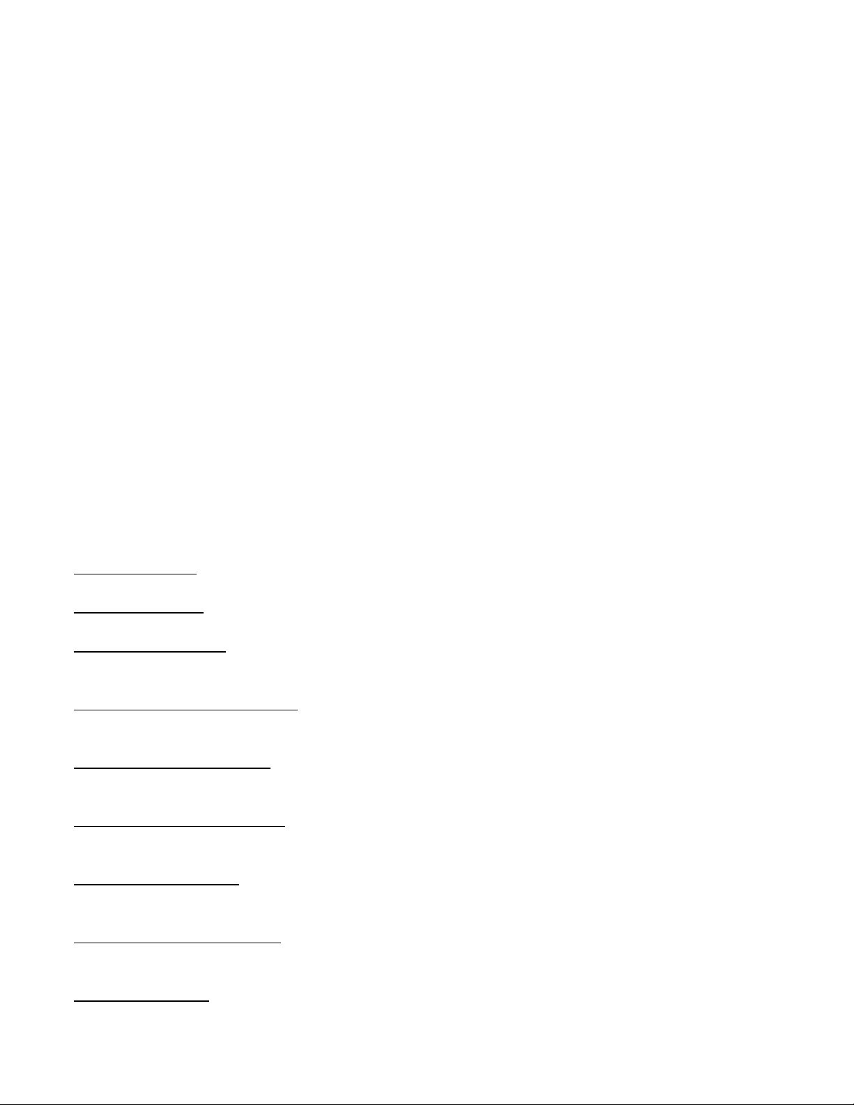
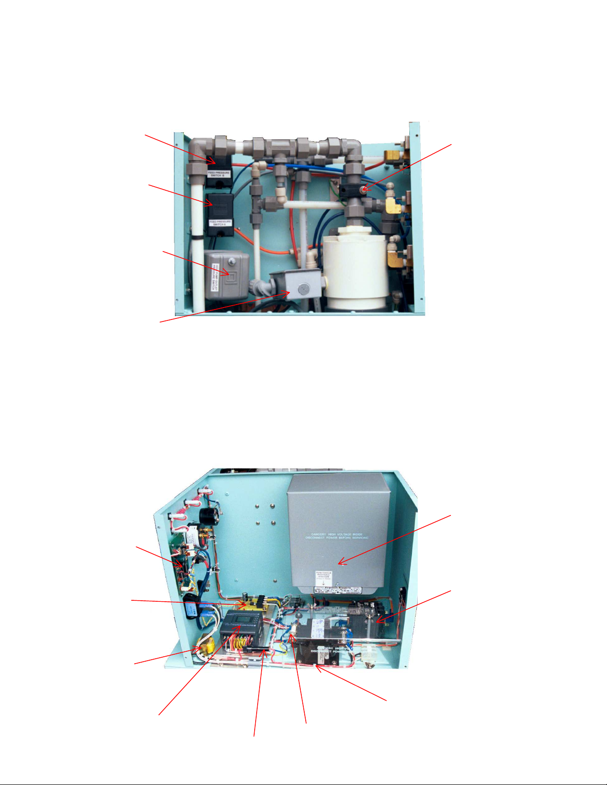
The operation of the system is best studied with the prefilter housings removed and the top cover off.
Refer to the attached water flow schematic, Figure 5.
Feed water enters the system through a 3/4" MPT bulkhead and passes the main shut off valve before
entering the prefilters. After the prefilters the water passes through the feed water solenoid valve and
then through the feed pressure regulating valve. Then it joins any product or reject recycle flows and
enters the bottom of the submerged pump. The pump inlet pressure is sensed at this point.
The high pressure water comes out the top of the pump, tees to the pump outlet pressure gauge, and
goes to the bottom side of the 1st module. The reject water from this module is the feed for the second
module. The reject water from the second module is the feed for the third module. The reject from the
third module passes through a strainer and then splits. A portion of the water passes through the short
1/4" OD tubing capillary, through a spring loaded check valve, and then goes to the drain standpipe.
Another portion passes through the pressure control valve and joins the pump inlet flow. When the
green flush valve is opened, the capillary is bypassed and drain flow increases. When the reject to tank
valve is opened, the reject water that would otherwise flow to drain is directed into the disinfection tank.
In disinfection mode, a portion of the high pressure reject water passes through the green handled
venturi supply valve to drive the venturi. The venturi lifts the water from the tank into the pump.
The product water from the two or three RO modules is manifolded together and sent through the
flowmeter, a check valve, and then exits the system. The product line also tees to drain through the
product dump solenoid valve and tees to the disinfection tank through both the fill tank solenoid valve
and the product to tank valve.
Unused product water from the distribution loop returns at a 3/4" MPT bulkhead, a check valve, and
product back pressure regulator(s). Discharge from the regulator(s) goes back into the pump inlet
manifold. If two or more SPD units are in parallel, a product return solenoid valve is also in line. This
valve opens whenever the submerged pump runs.
Each RO module has a tap to the annulus volume just below the chevron brine seal. ¼” tubing from
these taps lead to check valves the outlet of which are manifolded and connected to a SS annulus drain
valve. Opening this valve during rinsing positively drains this otherwise dead space.

G01
SPD Owner's Manual
9
FIGURE 5

G01
SPD Owner’s Manual
10
INSTALLATION
General: The RO system should be located indoors in a location protected from excessive heat, cold,
or dust. The system must sit on a level floor and space in front and to both sides should be provided for
service. See outline dimensions in Figure 6.
Electrical: The system requires a source of grounded 220 volt, 60 Hertz ("H" model is 50 Hertz), 1
phase power. The power conduit should enter the rear of the system at the nominal 3/4" conduit hole
(1.06 inches actual diameter). In addition to the two power wires, a good ground wire of the same size
must be connected.
The electrical power connects to a two position terminal block inside the right hand side of the system.
The control box cover, held on by eight 6-32 Phillips screws must be removed. Then undo the two wing
nuts to remove the clear high voltage guard. Make certain that the screw terminals that clamp the
power wires are very tight. Connect the ground wire to the screw stud where the other green ground
wires are attached.
Drain: Waste water exits the RO system through a rubber sleeve connection that fits nominal 1 & 1/2
inch drain pipe (actual OD is 1.9 inches). The rubber sleeve connection tightens with a hex head (5/16"
or 8 mm across flats) screw on the SS band clamp. Use a long socket extension or a nut driver to
loosen the clamp. Remove the existing stub pipe placed for shipping.
The drain pipe can be run level or with a slight downward pitch to a "U" trap and into a sanitary sewer
line.
Feed Water: Presoftened and dechlorinated feed water enters the system at a 3/4" FPT plastic fitting
on the left side. Do not undersize the feed water piping to this point. A minimum pipe/tube/hose ID of
3/4 inch is recommended.
If the seal cone union provided is used, no TFE tape is required on the inlet fitting. However, it is
mandatory that the 3/4" MPT user connection have a smooth and beveled ID to match the seal cone.
Good installation practice allows for the inlet piping to be easily removed if service and access is
required. In general, a flexible inlet connection that does not transmit constant strain on the pipe joint is
preferred. If rigid piping is used, positioning should be exact and threaded unions should be used to
allow disassembly and correction of potential pipe thread leaks.
Product Water Outlet: The product output flow from the system exits at a 3/4" MPT nipple. The same
piping considerations expressed for the feed water connection above also apply to this fitting.
Product Water Return: Unused product water returns to the RO system at this 3/4" MPT connection. It
is recommended that initially this connection not be made until any piping debris in the distribution loop
is flushed to drain. If the product line is run dead ended, without a return from the loop, a bypass
assembly from product outlet to product return must be used.

G01
SPD Owner's Manual
11
INITIAL START UP
First open the prefilter vent valve. Turn on the feed water to the system and then open the main shut
off valve. After a few minutes the air in the prefilter will escape and the vent valve can be shut.
Make certain the mode switch is in the "Service & Rinse" position and turn on the system at the circuit
breaker/power switch. Before shipment a wire was detached from the Keyence PLC so the pump will
not start. Turning on the system does open the feed solenoid valve however and commences water
flow.
Open the green flush valve to hasten the purging process.
Open the pump vent valve and the annulus drain valve to expel air from the housing. Close it after a
minute or two.
After some time the air will all be displaced and a small flow through the product water flowmeter will
commence.
Now close the green valve and turn off the system. Remove the control cover and reattach the brown
wire to Keyence output terminal #502.
Now turn on the system. There will be a loud noise as the motor contactor is pulled in and the pump
should start.
If the low feed warning light comes on and the pump stops, turn the system on and off again to reset it.
After several minutes, the operation should stabilize with about 20 PSI of feed water pressure, 185 to
195 PSI pump outlet pressure, and up to 50 PSI product pressure.
Check for leaks.
Before the system is used productively, it should be put in a disinfection cycle.
Disinfection Instructions
Need for Disinfection: While the reverse osmosis membrane is an efficient physical filter for the
removal of bacteria and viruses in the feed water, the ability to deliver near sterile water with low
pyrogenicity is dependent upon periodic disinfection of the RO membrane and all portions of the product
water pathway. Assurance of bacteriological quality also requires regular sampling and testing of the
product water for pyrogen level with an LAL test.
Since any chlorine that might have been in the feed water was removed prior to the RO system, there is
nothing in the water to inhibit the growth of bacteria. Bacterial growths on the feed side of the
membrane can reduce output quantity and quality. Bacterial growths on the product side of the
membrane or anywhere on inside surfaces downstream constitute a biofilm that will release pyrogens
and live bacteria.

G01
SPD Owner’s Manual
12
Chemicals for Disinfection: The recommended disinfectant to use is RenalinTM or MinncareTM, both
products of Renal Systems, Inc. HDC Medical makes a similar formula with the trade name
PeracidinTM. These are near identical formulations of a mixture of hydrogen peroxide and peracetic
acid.
Research has shown that a 36 minute exposure to a 1% RenalinTM solution will give a 6 log reduction in
bacteria level on an RO system. It is much faster and more effective than other chemical disinfectants.
Indeed it is considered to be a cold sterilant. A 1% RenalinTM solution can be left in contact with
otherwise clean membranes for 12 hours maximum without membrane damage.
Up to 2% formaldehyde solution can also be used for disinfection. However it must be left to soak a
much longer time and is slower to rinse out. Formaldehyde also causes a temporary flux (output) loss
that persists for hours.
Never use chlorine bleach on this RO system!
Chemical test strip kits are available for checking the concentration achieved and for testing for residual
disinfectant after rinsing.
Acid Clean First:. If the feed water supply contains any traces of oxidized iron or manganese, an acid
cleaning should be performed prior to disinfection with MinncareTM. This is necessary to prevent a
membrane chemical attack for which the iron acts as a catalyst.
Problem oxidized iron and manganese are typically evident by reddish brown (iron) or black
(manganese) particulates collected on the prefilter elements. Examination of the inside of fittings
downstream of the prefilter will indicate the extent of deposits to be expected on the membrane. If the
deposits are heavy, use of a finer 1 micron prefilter may be warranted.
Acid cleaning is done following a similar procedure as disinfection (Page 14) and is discussed further on
Page 22.
The volume of water contained in the RO membrane modules, piping, and disinfection tank is about 35
liters. So to attain a 1% MinncareTM concentration, some 350 ml of Renalin concentrate is required.
Normally formaldehyde comes as a 37% solution. So a 2% concentration would require almost 2 liters
of concentrate.
Disinfection Procedure Overview: To be effective, a proper level of disinfectant must be introduced to
all portions of the feed water path downstream of the prefilters and all portions of the product water
path. Note that to accomplish this, disinfectant flow must be forced into the reject and product pressure
regulators. When the flush valve is open, there is no flow through the reject regulator. When either the
product to tank valve, the product sample valve, or the product dump valve are opened, there is no
pressure to force the disinfectant through the product regulator valves. So these valves must be closed
part of the time to cause the disinfectant to enter the regulators.
The same concern occurs during rinsing. When water is flowing through the regulator valves, any
disinfectant is going back into the pump inlet rather than to drain. So the flow through the regulators
should be made after the majority of the disinfectant is already rinsed out.

G01
SPD Owner's Manual
13
Some amount of disinfectant “rebound” will occur. This is when a disinfectant residual reappears after a
period of RO shutdown even though it was not present earlier. Rebound is minimized in the SPD RO
due to use of Circserts and the annulus drains, but still exists. This is because of disinfectant trapped in
the dead ended tubing to the pressure gauges, or anywhere that was not or cannot be properly rinsed.
Hazards of Leaks: The recommended MinncareTM disinfectant is very corrosive to most metals and
several plastics. If any of the diluted disinfectant leaks to the outside at tubing connections, the spilled
disinfectant has the potential of destroying the fitting over time. So any leaks must be hand rinsed
copiously and dried.

G01
SPD Owner’s Manual
14
Detailed Disinfection Procedure
1) The SPD RO system, the product water distribution loop, and the inlet hoses to the attached dialysis
machines are disinfected together.
2) Insert key and turn keylock clockwise. Remove the front cover. With the system running normally in
the "Service & Rinse" mode, press the "Fill Tank" pushbutton.
When the tank is full, the solenoid valve filling it with product water will close.
3) Switch the mode from "Service & Rinse" to "Disinfection." The RO will need to be turned off and on
again to restart. As soon as it starts, open the Venturi Valve.
4) Then open the Product to Tank and the Reject to Tank Valves.
Now all the solution is circulated to and from the 5 gallon disinfection tank. If the tank looks too
full to accept the volume of disinfectant required, the Reject to Tank Valve can be closed briefly
to lower the level.
5) Inspect for any leaks.
6) Put on gloves and eye protection.
7) Measure out 350 ml of Renalin into a suitable container, and add the disinfectant to the 5 gallon jug.
Do not spill!!!!! Any spills of Renalin concentrate must be copiously rinsed and wiped up with a
sponge, towel or vacuum.
The disinfectant should be circulating through the pump, membrane modules, and back to the
disinfection tank. The disinfectant in the product water will cause the high conductivity alarm
lamp to illuminate.
8) After a couple of minutes, open the Flush Valve about 1/3 of the way. Operate the system for at
least 5 minutes in this fashion.
9) Open the Annulus Drain Valve for about 15 seconds.
This exposes the hidden annular volumes (dead spaces) in the membrane modules to
disinfectant.
10) Close the Product to Tank Valve.
The disinfectant laden product water will now flow through the distribution loop , the product
pressure regulators, and back to the pump inlet.
11) Open the Product Dump Valve for 10 seconds.
The SPD system has a Product Dump Solenoid Valve which opens automatically at high product

G01
SPD Owner's Manual
15
conductivity (during Service and Rinse) and can be opened and closed manually by pressing the
Mute button for 3 seconds.
12) Turn on the connected dialysis machines in a rinse mode.
When the tank empties the SPD will shut off. Note the time.
13) Turn off the dialysis machines. Turn off the Power Switch/Circuit Breaker on the SPD system.
Switch the Mode Rocker Switch from “Disinfection” to “Service and Rinse” position. Close the Product
to Tank and the Venturi Valves.
14) Allow the disinfectant to soak at least 40 minutes to kill all microorganisms.
15) When it is time to rinse, turn on the system Power Switch and note the time.
16) Manually open the Product Dump Valve.
The Product Dump solenoid Valve will open because of the high product conductivity of the
product water. However it will close again as the conductivity falls. For faster rinse the Product
Dump Valve must remain open.
17) Open the flush valve as much as possible (without letting the machine shut off due to low pump inlet
pressure) to hasten the initial rinse.
The progress of the rinsing is indicated by the product water conductivity falling relative to what it
normally is.
18) After the product conductivity is within 1 or 2 microSiemens/cm of the normal value, close the Flush
Valve.
19) Open the Annulus Drain Valve for about 1 minute.
20) Cycle the Pump Vent Valve open for about 2 minutes.
21) Wait another 10 minutes and close the Product Dump Valve.
This will rinse out the distribution loop and product pressure regulator circuit but will, after a
delay, temporarily cause the product conductivity to rise.
22) Turn on the attached dialysis machines. Note the product water conductivity.
Now to rinse the disinfection tank and fluid paths to and from it.
23) Open the Product to Tank Valve for 30 seconds.
24) Push the Fill Tank pushbutton.
25) When the tank fills up with product water and shuts off the solenoid, once again put the mode
switch in “Disinfection.”

G01
SPD Owner’s Manual
16
26) Start the RO system by turning the Power switch off and on again.
27) Immediately open the Venturi Valve.
28) Open the Product Dump Valve.
29) Open the Reject to Tank valve for about 10 seconds.
The tank will quickly empty with no water returning to it and the system will shut down.
30) Put the Mode switch back in Service position. Using the key, turn the Disinfection Lock switch CCW
to normal and store the key.
31) After 5 minutes, start the system again by toggling the Power Switch off and on again.
There will probably still be a slight residual of disinfectant (rebound) which is detectable by the
Product water conductivity quickly falling to a low value, but higher than that noted in Step 21.
After a minute or two longer the conductivity should fall to the lower value.
32) Check for disinfectant residual at the drain of each dialysis machine.

G01
SPD Owner's Manual
17
NORMAL OPERATION
Normally the RO system is turned on in the morning, allowed to run all day, and turned off at the end of
the day. It should be allowed to operate for 10 minutes after each start up before the water is used for
productive purpose.
During normal operation, the pump inlet pressure gauge should read up to about 20 PSI, the pump
outlet pressure gauge should read about 190 to 200 PSI, and the product pressure will read up to 50
PSI. When all the product water is all used or sent to drain, the product pressure will be near zero.
The product water flowmeter should show the rated output in liters per minute of product flow with room
temperature feed water and proportionately less with cold feed water. The product flow is greatest
when the product pressure is minimal.
The reading of the product water conductivity monitor should be 4% or less that of the feed conductivity.
This is equivalent to a rejection of 96% or greater.
ALARM CONDITIONS
There are three warning lamps that indicate an abnormal alarm condition.
The Low Feed Pressure lamp will illuminate and the system will stop if the feed water pressure has
fallen low enough (to about 2 PSI) to trip out either feed pressure switch A or B. The system will remain
in this condition until it is manually turned off and on again with the power switch.
Low feed pressure shutdowns should not be tolerated. Whatever is causing the inadequate feed water
flow should be corrected.
After a 30 second start up delay, the High Conductivity lamp will be illuminated whenever the product
water conductivity exceeds the alarm point. The factory set alarm point is 20 ppm but the alarm point
can be adjusted to a more appropriate value as required. High conductivity will also cause the product
dump valve to open.
The Prefilter Pressure Drop lamp will be illuminated whenever the prefilter elements have been
operated beyond a 15 PSI pressure differential (this is the high end of the green band on the P
gauge). The lamp will stay illuminated until the system is turned off and on again. The lamp is an
indication that it is time to change the prefilter elements.
The Low Feed Pressure will flash on and off and the system will shutdown if the pump outlet pressure
exceeds 205 PSI. The system will remain in this condition until it is manually turned off and on again.
Any of these alarm conditions will also cause the audible alarm to sound. Pushing the Mute pushbutton
will silence the alarm for 2.9 minutes.
OTHER SHUTDOWNS
If there is a gross electrical short, the circuit breaker/power switch will trip and shut the system off. The
rocker handle of the switch will then be in a middle position between on and off. After letting the switch

G01
SPD Owner’s Manual
18
cool down for several minutes, turn all the way off and then on again to restart.
The Franklin pump electrical power box has an overcurrent thermal sensor that will trip if the pump
motor draws excessive current. The button is on the bottom of the box. The overload button is
accessible after removing the control panel cover, see Figure 3. After allowing several minutes for cool
down, press the red button to reset.
The control fuse will open if there is a short in the low voltage control circuitry. The fuse must be
replaced to resume operation.
The occurrence of any of these shutdowns indicates something was wrong. Resetting the protective
device will likely merely allow the shutdown to repeat. So service is indicated.
MONITORING SYSTEM OPERATION
A log of pertinent operating conditions should be kept so the condition of the RO system and especially
the membranes is tracked. Doing so reveals trends that help insure preventative maintenance is
performed rather than emergency service. It also provides a record that indicates the system is
performing as expected.
ELECTRICAL CONTROLS
Description: Refer to the enclosed electrical schematic, Figure 7. The incoming electrical power all
passes through the two pole circuit breaker/power switch. From there power is supplied to the pump
contactor (R1) and to the control transformer. A primary tap on the transformer supplies 115 volts AC to
the conductivity monitor through an inline fuse. The secondary side of the transformer provides 24 volts
AC.
An auxiliary circuit board rectifies and regulates the 24 volts for use by a Keyence PLC (programmable
logic controller). This board also contains an opto-isolator for accepting the alarm output voltage from
the conductivity monitor.
The Keyence PLC runs a program written for the SPD system. The program can be changed on a
personal computer with the Keyence software loaded. A cable connection allows transfer of the
program to the Keyence. The ladder logic program and inputs and outputs used by the Keyence are in
Appendix A.
The Keyence outputs operate the solenoid valves, lights, alarm and R1 with 24 VAC. To achieve
maximum life from the relay contacts in the Keyence, varistors are placed around all coils.
If the Keyence PLC were to fail, emergency operation could be achieved by jumpering the outputs on
the PLC that control the feed solenoid and R1. See troubleshooting.
Relay contactor R1 applies power to the Franklin Control Box. This box contains a thermally actuated
overload, a starting capacitor, a running capacitor, and a potential relay. At first power is applied to both
the start and the run windings. The coil of the potential relay responds to the voltage on the run winding
and opens up the start winding when this voltage is high enough. Some current in the start winding is
This manual suits for next models
1
Table of contents
Popular Water Filtration System manuals by other brands

AQUA FORTE
AQUA FORTE EconoSieve instruction manual

Aqua Medic
Aqua Medic NR 5000 Operation manual

HomePlus
HomePlus UltraPlus+ UP-12 Owner's manual and installation instructions

System air
System air Fantech HERO HS300 Installation and operation manual

Greenlife
Greenlife Biovitor Installation and maintenance instruction

AIR GAP
AIR GAP AG110-003 quick guide