BANGGOOD GT01 User manual
G P S Tracker U s e r
Ma
nu
a
l
GT01

1
Directory
1 LED Status ........................................................................................................... 2
2 Work Mode......................................................................................................... 3
3 Wiring connections.......................................................................................... 3
4 Connect the Relay............................................................................................ 4
5 The Place of the tracker in the Vehicle..................................................... 4
6 Work Mode......................................................................................................... 5
7 Tracker Default Work Mode......................................................................... 5
8 Command ........................................................................................................... 6
9 Specification.....................................................................................................14
10 Special Command ..........................................................................................15

2
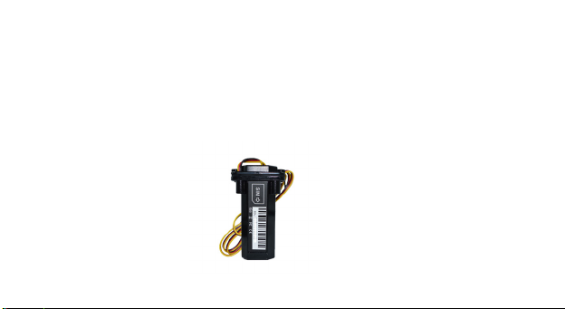
GPS/GSM Tracker is a vehicle remote positioning device with built-in GPS/GSM/GPR
S technology in compact size. It can transmit the longitude and latitude coordinates to your
cell phone by the SMS. User could use the coordinates to find its location on the Google
maps or other map software. The tracker also uploads position data to a designated server t
hrough GPRS. User can look for real-time location-tracking and historical track through th
e our web base server.
1LED Status
Orange LED--- GSM signal status
Light On = GSM work Flash = No GSM network or SIM card not detected
Blue LED: GPS signal status
Light On = GPS work Flash = GPS No Work or No GPS Signal
Red LED: Battery status
Flash = Charging/Working Light Off = No Power

3
2Work Mode
This tracker have two work mode which is SMS and GPRS Mode. SMS mode is for off l
ine tracking by Mobile phone. GPRS Mode is for on line tracking by computer and mobi
le phone .
3Wiring connections
Red - (+)12V -24V
Black – ground (-)
Yellow – SOS button (-)Connect other side of switch to ground (-)
White- engine immobilizer (-) (optional connection)
Green - ACC detect, stop battery charge while vehicle off

4
4Connect the Relay
The white cable is control the fuel of the car and connects pin 86 of relay which is a coil
end. Pin 85 of the relay which is another coil end connects fuel channel to supply 12V po
wer (please note working volt of the relay is consistent with working volt of the product).
Pin 30 and Pin 87a are always closed ends and connect fuel channel power circuit in seri
es. Please install wire in a correct way. supplier will not be responsible for device damag
e caused by wrong installation.
5The Place of the tracker in the Vehicle
Front windshield decorative below the covert
Front panel (skin for non-metal material) around the shadow
Rear window below decorative

5
6Work Mode
This tracker have two work mode which is SMS and GPRS Mode. SMS mode is for off
line tracking by Mobile phone. GPRS Mode is for on line tracking by computer and
mobile phone .
7Tracker Default Work Mode
The Original password of the tracker is : 0000
6
The Default battery switch is : OFF
The Default work mode is : Sleep Mode
The Default Voice is : ON
About the Alarm information, The Tracker will send all of the alarm information to the
first pre-saved number except the SOS Alarm that send it to all 1, 2 ,3 pre-saved number
8Command
Set Controller phone number
Command: * controller phone
number * user password
*Sequence number (1-3) **
Eg: 1390000000000001-3
Reply: SET USER NUMBER 1-3 OK
Note:
1.Tracker can have three pre-saved number
2.New Number can cover the old number
3.No pre-saved number also can control the tracker, but alarm information only to pre-saved number
Work Mode Exchange Eg: 7000000
7
SMS Mode Command:700+ user
password
GPRS Mode Command:710+
user password
Reply: SET MODE OK, CURRENT MODE: SMS
Eg: 7100000
Reply: SET MODE OK, CURRENT MODE: GPRS
Change user password
Command: 777+new password
+old password (4 figures)
Eg: 77712340000
Reply: SET USER PASSWORD OK
Request the single position
Command: 666+ user password
eg: 6660000
Reply: when the tracker receive the command, then
will send the position with longitude and latitude
Request location with Google
map URL link
Command 1: 669+ user password
Eg: 6690000
Reply: When the tracker receive the command, tracker
will send a Google link to the sender
Daily Report
Command: 665+user
password+HHMM
Eg: 66500001022
Reply : SET DAILY REPORT OK

8
Close timing report: 665+user
password+OFF
Eg: 6650000OFF
Reply : SET DAILY REPORT OFF
Note:
HH stands for hour with defined range of [00, 23]. MM stands for minute with defined range of [00,
59].
SOS Alarm
When press the SOS button more
than 3 seconds, it will call and
send location to three controller
Phone number , the information state is "STA TE:
SOS"
Geo- Fence
Turn On Geo-fence
Command: 211+ password
Eg: 2110000
Reply: GEO-FENCE ON
Set Geo Fence Command: 005+user password+Rzzz.z
Eg: 0050000R1.0 (1000M) Reply: GEOFENCE ON
Turn geo-fence off
Command: 210+ password
Eg: 2100000 Reply: GEO-FENCE OFF

9
Battery low voltage alert
While device detect internal battery is low power, it
will send the position message with STA TE: Power
Low Alarm
Cut Fuel
Open Cut Fuel Command: 940 +
user password
Eg : 9400000
Reply : POWER OFF OK
Close Cut Fuel command : 941 + user password
Eg:9410000
Reply : POWER ON OK
Alert while power off
Open the power off alert
Command: 010 + user password
Eg: 0110000
Reply: POWER ALARM ON
Close the power off alert Command: 011 + user
password
Eg: 0110000
Reply: POWER ALARM OFF
Tow alarm Eg: 181000015 (15 seconds)
Table of contents


