Barnstead International 1305 Series User manual

EASYpure®II RF
OPERATION MANUAL
AND PARTS LIST
Series 1305
Model D7031
100-240 Volts
LT1305X1 • 8/22/05

Safety Information ..............................................................................................................................................4
Alert Signals..................................................................................................................................................4
Warnings ......................................................................................................................................................4
Introduction..........................................................................................................................................................6
General Specifications ........................................................................................................................................7
Dimensions and Clearance Requirements. ..................................................................................................7
Electrical Requirements ................................................................................................................................7
Feedwater Requirements..............................................................................................................................7
Product Water ..............................................................................................................................................7
Environmental Conditions ............................................................................................................................8
Declaration of Conformity ............................................................................................................................8
Unpacking ..........................................................................................................................................................9
Installation ........................................................................................................................................................10
Locating Unit ..............................................................................................................................................10
Cartridge Installation ..................................................................................................................................11
Controls ............................................................................................................................................................12
Power Switch ..............................................................................................................................................12
Control Panel ..............................................................................................................................................12
Switches......................................................................................................................................................12
Display..................................................................................................................................................12
Operational Modes......................................................................................................................................13
Run Mode ............................................................................................................................................13
Standby ................................................................................................................................................13
Idle Mode..............................................................................................................................................13
Initial Operation ................................................................................................................................................14
Storage Reservoir Filling and Cartridge Rinse Up......................................................................................14
Normal Operation ..............................................................................................................................................15
Operation ....................................................................................................................................................15
Water Draw-Off ..........................................................................................................................................15
Feedwater Replenishment ..........................................................................................................................15
Maintenance and Servicing ..............................................................................................................................16
System Sanitization ....................................................................................................................................16
Cleaning the Resistivity Cell ......................................................................................................................18
General Cleaning Instructions ....................................................................................................................20
Cartridge Replacement ..............................................................................................................................20
Cartridge Removal ......................................................................................................................................21
0.2 Micron Final Filter Replacement ..........................................................................................................21
Ventgard Cap Replacement........................................................................................................................21
Fuse Replacement......................................................................................................................................22
Unit Shutdown ............................................................................................................................................22
Troubleshooting ................................................................................................................................................23
Error Conditions ..........................................................................................................................................25
Replacement Parts............................................................................................................................................26
Consumables ..............................................................................................................................................26
General Maintenance..................................................................................................................................26
Safety Stock................................................................................................................................................27
Wiring Diagram..................................................................................................................................................28
Ordering Procedures ........................................................................................................................................29
One Year Limited Warranty ..............................................................................................................................32
2
Table of Contents

3
Figures
Figure 1: EASYpure II RF Front ........................................................................................................................10
Figure 2: EASYpure II RF Back ........................................................................................................................10
Figure 3: Cartridge Installation ..........................................................................................................................11
Figure 4: Control Panel ....................................................................................................................................12
Figure 5: Disconnecting Resistivity Cell ............................................................................................................18
TABLE OF CONTENTS

4
Safety Information
Warning
Warnings alert you to a possibility of
personal injury.
Caution
Cautions alert you to a possibility of
damage to the equipment.
Note
Notes alert you to pertinent facts and
conditions.
Alert Signals Your Barnstead EASYpure®II RF has been designed
with function, reliability, and safety in mind. It is your re-
sponsibility to install it in conformance with local electri-
cal codes. For safe operation, please pay attention to
the alert signals throughout the manual.
This manual contains important operating and safety
information. You must carefully read and understand the
contents of this manual prior to the use of this equip-
ment.
Water purification technology employs one or more of
the following: chemicals, electrical devices, mercury
vapor lamps, steam and heated vessels. Care should be
taken when installing, operating or servicing Barnstead
products. The specific safety notes pertinent to this
Barnstead product are listed below.
Warnings
To avoid electrical shock, always:
1. Use a properly grounded electrical outlet of
correct voltage and current handling capacity.
2. Do not place the EASYpure II RF directly
over equipment that requires electrical serv-
ice. Routine maintenance of this unit may
involve water spillage and subsequent electri-
cal shock hazard if improperly located.
3. Replace fuses with those of the same type
and rating.
4. Do not disassemble water lines or remove
cartridges where spilled water could contact
equipment that requires electrical service.
Electrical shock hazard could result.
5. Disconnect from the power supply prior to
maintenance and servicing.
To avoid personal injury:
1. Do not use in the presence of flammable or
combustible materials; fire or explosion may
result. This device contains components
which may ignite such materials.

2. Do not use in the presence of highly corrosive
substances such as bleach or acid baths; fire
may result.
3. This device is to be used with water feeds only.
Sanitizing/cleaning agents must be used in
compliance with instructions in this manual.
Failure to comply with the above could result in
explosion and personal injury.
4. Avoid splashing disinfecting solutions on cloth-
ing or skin.
5. Ensure all piping connections are tight to avoid
chemical leakage.
6. Carefully follow manufacturer’s safety instruc-
tions on labels of chemical containers and ma-
terial safety data sheets.
7. Refer servicing to qualified personnel.
8. Ensure adequate ventilation.
9. Depressurize system prior to opening cartridge
access door or removing top cover.
5
SAFETY INFORMATION

The Barnstead EASYpure II RF is a batch-fed water puri-
fication system designed to provide Type I reagent-grade
water with extremely low organic carbon content. It uses
a three-stage deionization process combined with a 0.2
micron final filter to polish pretreated water (distilled,
deionized, or reverse osmosis) to produce water with a
resistivity of up to 18.2 megohms-cm and with a total
organic carbon content of less than 10 ppb. Water resis-
tivity is continuously sensed by a resistivity cell and dis-
played on a digital display.
The EASYpure II RF is designed to be a bench mounted
unit. If wall mounting is required, contact Barnstead
International customer service for information on a wall
bracket and mounting accessory.
6
Introduction
EASYpure II RF

Dimensions and Clearance Requirements
EASYpure II RF dimensions - 12" W X 19" D X 18 1/8" H (30.5 cm X 48.3 cm X 46.0 cm).
Clearances:
Sides - 4" (10.1 cm) minimum to allow air flow
Above - 12" (30.5 cm) minimum for reservoir replenishment
Cartridge replacement requires that you be able to access the back of the unit and open the cartridge
access door (total depth, unit + open door, = 34") (86.4 cm).
Storage Reservoir Capacity - Approximately 6.5 liters usable, 7.0 liters total
Electrical Requirements
The EASYpure II RF is equipped with two power cords and corresponding fuses taped to each power cord to
be plugged into a grounded electrical outlet of the appropriate voltage.
Model D7031: 100-240 VAC +5% -10%, 47-63 Hz.
Feedwater Requirements
The EASYpure II RF requires water pretreated by either distillation, deionization or reverse osmosis.
TOC - Less than 1.0 ppm
Turbidity - Less than 1.0 N.T.U.
Temperature - 40°F - 104°F (4.4°C - 40°C)
Silica - Less than 1 ppm
TDS (CaCO3) -
RO - Less than 50 ppm
DI - Less than 100 ppm
Distilled - Less than 2 ppm
Product Water
Quality
Resistivity: ASTM Type I
TOC: 5-15 ppb
Flow Rate: greater than or equal to 0.8 LPM with a new final filter
7
General Specifications

Environmental Conditions
Operating: 4°C - 49°C; 20% - 80% relative humidity,
non-condensing. Installation Category II (overvoltage) in
accordance with IEC 664. Pollution Degree 2 in
accordance with IEC 664.
Altitude limit: 3,500 meters.
Storage: -25°C - 65°C; 10% to 85% relative humidity.
Declaration of Conformity
Barnstead International hereby declares under its sole responsibility that
this product conforms with the technical requirements of the following
standards:
EMC: EN61000-3-2 Limits for Harmonic Current Emissions
EN61000-3-3 Limits for Voltage Fluctuations and
Flicker
EN 61326-1 Electrical Equipment for Measurement,
Control, and Laboratory Use; Part I:
General Requirements
Safety: EN 61010-1 Safety Requirements for Electrical
Equipment for Measurement, Control
and Laboratory Use; Part I:
General Requirements
per the provisions of the Low Voltage Directive 73/23/EEC, as amended
by 93/68/EEC.
The authorized representative located within the European Community is:
Electrothermal Engineering, Ltd.
419 Sutton Road
Southend On Sea
Essex SS2 5PH
United Kingdom
Copies of the Declaration of Conformity are available upon request.
8
GENERAL SPECIFICATIONS

Unpacking
Remove the unit from its shipping container and
ensure that the following items are removed from the
packaging materials before discarding:
a) EASYpure II RF unit
b) Ventgard®reservoir cap (CV703X4A)
c) North American power cord with attached fuse
bag (CRX72)
d) European power cord with attached fuse
(CRX70)
e) Operation Manual (LT1305X1)
9
Unpacking
Note
Cartridges and the 0.2 micron final filter
are not provided with the EASYpure II
RF and must be ordered separately:
EASYpure Kit Ultra low Organics
Deionized Feed (No Final Filter)
Part No. D502124
EASYpure Kit Ultra low Organics
Distilled or RO Feed (No Final Filter)
Part No. D502125
EASYpure Kit Type I Deionized Feed
(No Final Filter)
Part No. D502126
EASYpure Kit Type I Distilled or
RO Feed (No Final Filter)
Part No. D502127
0.2 Micron Final Filter
Part No. D3750

Locating Unit
1. Place the EASYpure II RF on a bench top con-
venient to your work area, noting the
Clearance Requirements. If wall mounting is
required contact Customer Service.
2. Using 1/2" I.D. tubing and tubing connectors
(user supplied), connect the overflow drain tub-
ing (lower left corner of the rear of the unit) to
an atmospherically vented sink or floor drain. If
an atmospherically vented sink or floor drain is
not accessible, a bucket or other container
may be placed on the floor beneath the
EASYpure II RF’s location and emptied when
full.
10
Installation
Figure 1: EASYpure II RF Front Figure 2: EASYpure II RF Back
Warning
Do not place the EASYpure II RF
directly over equipment that
requires electrical service. Rou-
tine maintenance of this unit may
involve water spillage and subse-
quent electrical shock hazard if
improperly located.
Warning
Do not use in the presence of flam-
mable or combustible materials; fire
or explosion may result. This de-
vice contains components which
may ignite such materials.
Warning
This device is to be used with water
feeds only. Sanitizing/cleaning
agents must be used in compliance
with instructions in this manual.
Failure to comply with the above
could result in explosion and per-
sonal injury.

Cartridge Installation (See Fig. 3)
1. Open cartridge access door in the rear of the unit
by pushing the door latch down.
2. Remove a new Pretreatment cartridge (part num-
ber D50230 or D50231) from its plastic bag.
3. Wet the o-rings with water on both end caps.
4. Press the upper end cap into the pretreatment
position until it bottoms out.
5. Lower the cartridge and insert the lower end cap
into the lower socket until it is firmly seated.
6. Repeat steps 2 - 5 with the Ultrapure cartridge
(Catalog No. D50233) and then the EASYpure
High Purity/Low TOC (Catalog No. D50229) or
Ultrapure cartridge, placing them in positions 2
and 3.
7. Close cartridge access door. This serves to veri-
fy the cartridges have been properly seated.
11
INSTALLATION
Note
The upper end cap is the one with the
right-angle turn and the two flanges.
The lower end cap extends straight
out from the cartridge. (See Fig. 3.)
Note
The two flanges on the end cap
should be able to slide down on each
side of the keyway wall.
Figure 3: Cartridge Installation
12
Power Switch
The power switch on the EASYpure II RF is located on
the back right side of the unit directly above the power
cord receptacle.
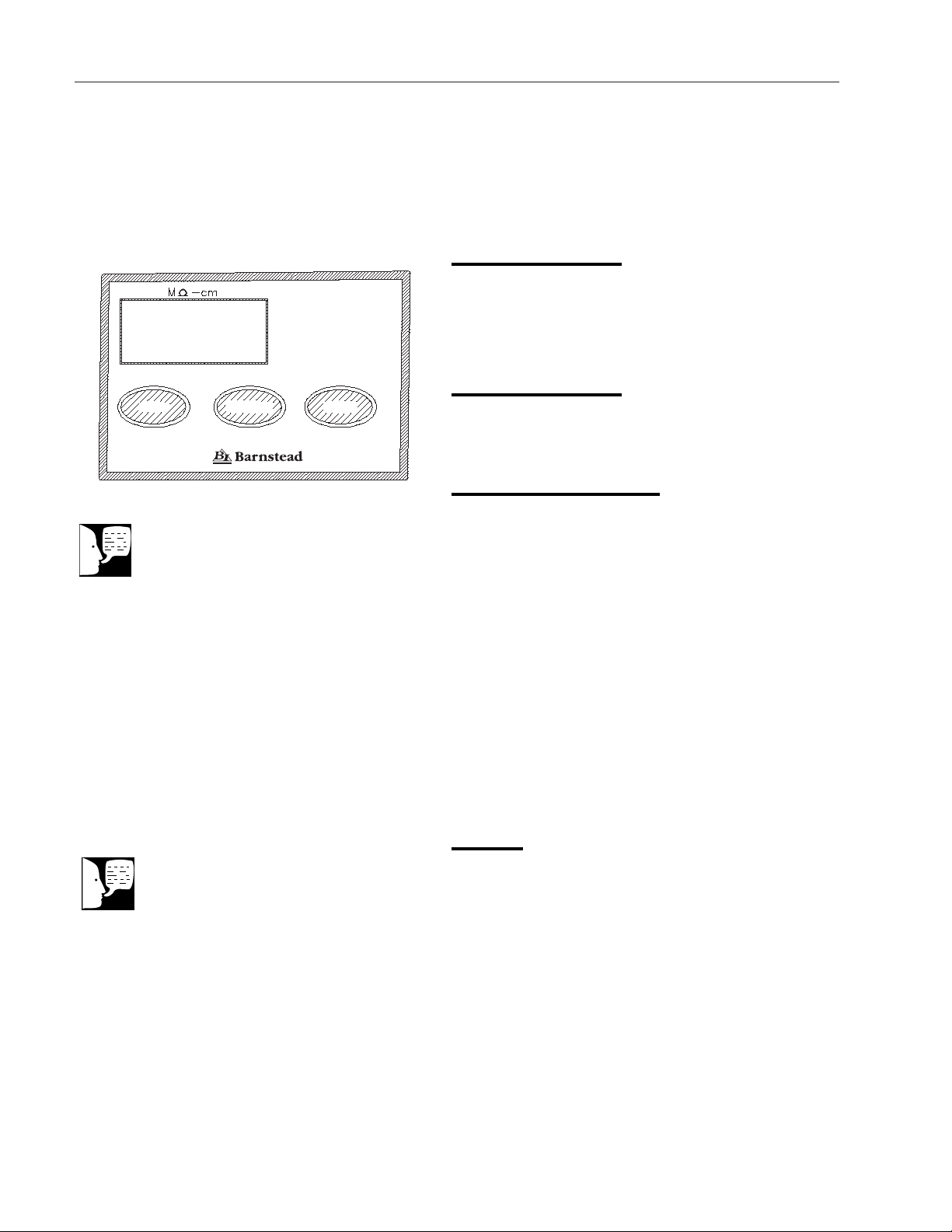
Control Panel
The EASYpure II RF control panel incorporates three
switches and a digital display.
Switches (See Fig. 4)
When the main power switch is on, the three switches
on the control panel function as follows:
1. START: Pressing the START switch when the
unit is in either the stop (“IdL”) or standby
(“SbY”) mode will put the unit into run mode.
2. STANDBY: Pressing the STANDBY switch
when the unit is in either the start (run) or
stop (“IdL”) mode will put the unit into a stand-
by mode.
3. STOP: Pressing the STOP switch when the
unit is in either the start (run) or standby
(“SbY”) mode will put the unit into a stop
(“IdL”) mode.
Display
In addition to displaying the temperature compensated
(25°C) resistivity in megohms, the display also indi-
cates operational modes and error indicators. The fol-
lowing is what can appear on the display:
SbY Er1
rEC Er4
IdL Er5
Add
Controls
Figure 4: Control Panel
STOP STANDBY START
Note
On initial start-up, the purity meter may
display “Er.1”. This is caused by air in
the cell and should soon be replaced
by a resistivity reading. If “Er.1” does
not go out after the pump has run for a
minute or if it appears any time while
the EASYpure II RF is in operation,
refer to the “Troubleshooting” section of
this manual.
Note
On initial power-up, the display will run
the following sequence:
- Model type is scrolled -RF
- The display’s LEDs will light up,
- Followed by the unit software
revision,
- Finally, IdL will be displayed.
Operational Modes
Run Mode
Since not all qualities of permissible feedwater will reach
maximum resistivity after one pass through the unit’s car-
tridges (especially as the cartridges near exhaustion), the
EASYpure II RF has two operational modes; run and
standby.
In the run mode, the pump continuously recirculates water
through the cartridges. It is recommended that the
EASYpure II RF be left in the run mode during the day. In
the run mode, the purity meter display indicates the resis-
tivity of the water available for draw off. Allow the water’s
resistivity to rise to the desired purity before drawing off
water.
STANDBY (“SbY”)
In STANDBY (“SbY”) mode, the pump will restart for ten
minutes out of every hour (i.e 50 minutes off, 10 minutes
on). The display reads “rEC” which indicates recircula-
tion. This will allow the unit to produce high quality water
quickly upon being placed in the run mode. It is recom-
mended that the EASYpure II RF be placed in the
STANDBY mode during non-work hours. At the end of
the work day, press the STANDBY switch on the front of
the EASYpure II RF to place the unit in STANDBY mode
for the night. “SbY” will appear on the display.
Idle Mode (“IdL”)
“IdL” indicates the unit is powered and waiting to be
placed in Run or STANDBY mode.
13
CONTROLS
Note
When the unit is first put in the Run
Mode, the display will show 10.0 for
a few seconds. This is an arbitrary
number that indicates the unit is run-
ning. Any number that appears after
10.0 indicates purity.
Note
Do not put unit into Idle Mode or
turn off the EASYpure II RF during
non-work hours. Doing so will allow
bacterial growth and other contami-
nation of the water in the system.
As a result, the system will require
a lengthy rinse-up period at the
beginning of the work day to
achieve high-quality product water.
Note
If the unit is in standby and power
to the unit is turned off or lost, the
unit will return to standby once
power is restored.

Storage Reservoir Filling and
Cartridge Rinse Up
To fill the reservoir:
1. Remove the molded plastic Ventgard cap.
2. Carefully pour pretreated feedwater into the reser-
voir until the water is level with the top of the sight
gauge on the front of the unit (See Fig. 1). Replace
the Ventgard cap.
3. The power connection is located on the right side of
the unit, in the upper back corner.
4. Determine which power cord you need (this will be
based on your country and outlets available in your
lab). Both North American and European power
cords are provided with the unit.
5. Remove the fuse holder, install the fuses included
with the power cord to be used, and reinstall holder.
6. Verify power switch is turned off and attach recepta-
cle end of power cord into the power socket.
7. Plug other end of power cord into facility power.
Turn main power on at power entry module.
8. Place suitable container under draw-off valve. Open
draw-off valve.
9. Press START and rinse one complete reservoir vol-
ume of water through the cartridges to drain.
10. Close draw-off valve.
11. Remove hose barb connection from draw-off valve.
Keep hose barb for future use.
12. Remove the new 0.2 micron final filter assembly
from its bag and insert it into the draw-off valve.
Gently tighten, turning the filter to the right.
13. Refill the reservoir with pretreated water.
14. Open the draw-off valve and flush second reservoir
volume of water through the 0.2 micron final filter.
Initial Operation
Note
Cartridge rinse up procedure must be
followed after each cartridge and/or fil-
ter replacement.
Note
In the event that you overfill the feed-
water reservoir, allow the excess water
to drain from the reservoir through the
overflow drain tubing before replacing
the Ventgard cap. This will prevent
wetting the filter element.
Note
For more demanding applications
where low TOC water is required, a
third reservoir volume rinse of the car-
tridges and filter may be necessary.
Teflon®is a registered trademark of DuPont
Warning
Use a properly grounded electri-
cal outlet of correct voltage and
current handling capacity.
Warning
This device is to be used with water
feeds only. Sanitizing/cleaning
agents must be used in compliance
with instructions in this manual.
Failure to comply with the above
could result in explosion and person-
al injury.
Note
It is suggested that Teflon®tape be
applied to the threads of the 0.2 micron
final filter to ensure a tight seal.
14

Operation
1. Remove the Ventgard cap. Do not allow water
to enter the Ventgard cap.
2. Carefully pour pretreated feedwater into the
feedwater reservoir until the water is level with
the top of the sight gauge. Replace the
Ventgard cap.
3. Turn main power on at power entry module.
4. Press the “START” button on the front of the
EASYpure II RF. The EASYpure II RF’s pump
will begin to run and the purity meter will dis-
play “10.0” followed by the number indicating
the resistivity of the water in megohm-cm.
5. Allow the water’s resistivity to rise to the
desired purity before drawing off water.
Water Draw-Off
1. Remove the protective cap from the 0.2
micron final filter bell.
2. Depress the draw-off lever.
3. When draw off is complete, lift the draw-off
lever and replace the protective cap on the 0.2
micron final filter bell.
Feedwater Replenishment
As water is drawn off from the EASYpure II RF, the feed-
water reservoir will require refilling. This will be indicated
by a low water level in the sight gauge or by the message
“Add” on the display. To refill the reservoir:
1. Repeat steps 1 and 2 from “Operation” above.
2. Allow the water’s resistivity to rise to the
desired purity before drawing off water.
15
Normal Operation
Note
When the unit is first put in the Run
Mode, the display will show 10.0 for a
few seconds. This is an arbitrary num-
ber that indicates the unit is running.
Any number that appears after 10.0
indicates purity.
System Sanitization
Frequency of cleaning is difficult to determine because of
variability in feedwater and usage. Cleaning is necessary
when residual deposits are evident inside the feedwater
reservoir or if a new 0.2 micron final filter clogs rapidly
after installation even though the cartridges were properly
rinsed before the 0.2 micron final filter was installed. To
sanitize the EASYpure II RF, remove the 0.2 micron final
filter and attach the hose barb that came installed on the
unit. The purification cartridges must be removed and
replaced with empty cartridges. These must be ordered
separately. Contact Barnstead International and order part
number D7034.
1. Drain the system.
a. Place the 0.2 micron final filter over a sink or
place a bucket or other suitable large container
under the filter and draw off water as described
under Water Draw-Off in the Operation sec-
tion of this manual. Draw off water until the
water level in the feedwater reservoir is lowered
to the point that the reservoir float switch dis-
ables the pump. Lift draw-off valve to closed
position.
b. Disconnect the power cord from the power
entry module.
c. Turn the unit around to provide access to the
drain plug on the lower edge of the back panel.
d. Place the drain plug over a sink, or place a
bucket or other suitable large container under
the drain plug. Remove the drain plug by turn-
ing it while pulling until it comes out.
e. Drain remaining water from the reservoir and
system.
f. Replace the drain plug, taking care to fully
insert it into the drain tubing.
g. Remove cartridges and install empty cartridge
tubes (part number D7034) according to the
instructions in Cartridge Replacement.
16
Maintenance and Servicing
Warning
Disconnect from the power supply prior
to maintenance and servicing.
Do not disassemble water lines or re-
move cartridges where spilled water
could contact equipment that requires
electrical service. Electrical shock haz-
ard could result.
Refer servicing to qualified personnel.
Note
The cartridges will still contain water
when removed. Therefore, you will
want to have a sink, bucket or other
waterproof container available to place
them in after removal.
Note
Asmall amount of water will drain from
the cartridge when it is disconnected
from the lower socket. Plug the car-
tridge’s lower opening with your finger
to minimize water spillage while you
finish removing the cartridge.
Note
Used cartridges may be recycled. See
P.U.R.E. information packed with new
cartridges.
Note
Drain plug is not attached to unit; use
care when removing it over an open
drain to avoid dropping it into the
drain.

h. Remove 0.2 micron final filter and install the
hose barb that was shipped with the system.
2. Remove Ventgard cap and pour 6 liters of pre-
treated feedwater into reservoir.
3. Add 10ml to 20ml of household chlorine bleach
(5.25% sodium hypochlorite) to reservoir.
4. Reconnect power cord to the power entry mod-
ule and turn unit on. Press the “START” button
and put unit into Run Mode.
5. Allow the unit to recirculate the disinfecting
solution for thirty minutes. Cycle the draw-off
valve to sanitize the valve.
6. Drain the system as described in step 1 of this
section.
7. Refill the reservoir with suitable feedwater and
recirculate the water through the system for ten
minutes.
8. Drain the system as described in step 1 of this
section.
9. Remove the empty cartridge tubes according
to the instructions in the Cartridge Removal
section. Drain and retain the empty cartridge
tubes for future use. Remove the hose barb fro
the draw-off valve.
10. Install and rinse new cartridges according to
the instructions in the Cartridge Installation
section. Do not reinstall used cartridges or 0.2
micron final filter (they may contain large
amounts of bacteria.)
11. Install and rinse new 0.2 micron final filter
according to the instructions in the 0.2 Micron
Final Filter Replacement section of this man-
ual.
12. Reconnect power cord to the power entry mod-
ule and turn unit on. Press the “START” but-
ton.
17
MAINTENANCE AND SERVICING
Warning
Avoid splashing disinfecting solutions
on clothing or skin.
Ensure all piping connections are tight
to avoid chemical leakage.
Ensure adequate ventilation.
Carefully follow manufacturer’s safety
instructions on labels of chemical con-
tainers and material safety data
sheets.
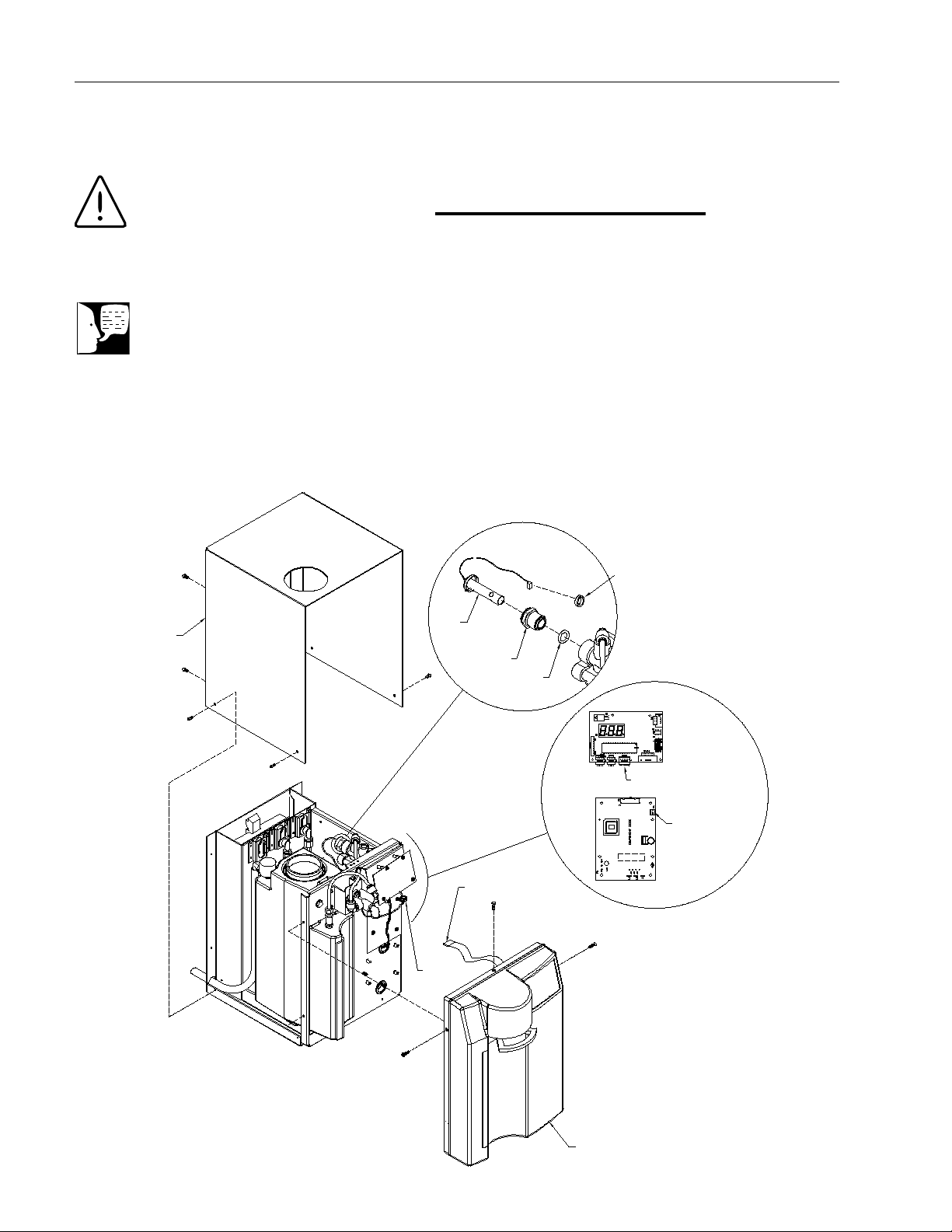
Membrane Switch Lead
Remove Front Cover
and Screws
Remove Top
Cover and Screws
Meter Board Display Board
Disconnect Cell
Lead From Here
Disconnect Membrane
Switch Lead From Here
EMI Filter
EMI/RFI
Suppression Filter
(one loop around filter)
Cell
Bushing
O-ring
Cleaning the Resistivity Cell
1. Turn off the EASYpure II RF. Remove the
power cord.
2. Depressurize the system by opening the unit
dispenser draw-off valve, allowing water to
drain until no more flows from the valve.
3. Remove the Ventgard cap.
4. Remove the screws securing the EASYpure II
RF top cover.
18
MAINTENANCE AND SERVICING
Warning
Depressurize system prior to opening
cartridge access door.
Note
Ensure you have an o-ring (part #
GSX29) available prior to cleaning
resistivity cell.
Figure 5: Disconnecting Resistivity Cell

5. Remove the cover by lifting it straight up.
6. Remove the 0.2 micron final filter. Carefully remove
the front cover screws and pull the cover off.
Disconnect membrane switch lead from the display
board (see Fig. 5).
7. Disconnect the cell lead from the meter board,
remove the EMI/RFI suppression filter and gently
pull the cable out of the EASYpure II RF frame.
Note orientation.
8. Unscrew and remove the cell.
9. Carefully remove and discard the o-ring before
cleaning the cell.
10. Wash the cell in a mild detergent solution followed
by a 10% Hydrochloric or 10% Sulfuric acid solu-
tion (follow acid manufacturers warnings and rec-
ommended handling procedures found on package
labels and Material Safety Data Sheets). This may
be done in an ultrasonic cleaner or with a soft
brush.
11. Thoroughly rinse the cell in deionized or distilled
water following the detergent and/or acid cleaning.
12. After cleaning, reinstall with the replacement
o-ring on cell (part # GSX29).
13. Reinstall the cell and hand tighten. Reroute the
cable up through the housing, reinstall the EMI/RFI
suppression filter (loop wire 1 time around filter)
and reconnect cell lead to meter board.
14. Reinstall membrane switch lead. While lifting dis-
pense handle, replace the front cover. Reinstall the
0.2 micron final filter.
15. Reinstall the EASYpure II RF top cover.
16. Reinstall the Ventgard cap and 0.2 micron final fil-
ter.
17. Reattach the power cord and reconnect the unit to
the power supply.
18. Refill the reservoir with feedwater and operate nor-
mally.
19
MAINTENANCE AND SERVICING
Caution
The cell electrodes are etched to
improve wetting characteristics. Do not
mechanically abrade or damage this
surface (i.e. do not clean with a wire
brush, sandpaper, etc.).
Do not immerse the entire cell assem-
bly in cleaning solution, only the elec-
trode portion.
Warning
Carefully follow manufacturer’s safety
instructions on labels of chemical con-
tainers and material safety data
sheets.

General Cleaning Instructions
Wipe exterior surfaces with lightly dampened cloth containing
mild soap solution.
Cartridge Replacement (See Fig. 3)
The frequency with which you will need to replace cartridges is
dependent on your feedwater characteristics, your purity require-
ments, and your daily usage. Replace the cartridges when the
product water purity drops below acceptable levels of resistivity
or when organic levels become too high.
Remember, used cartridges can be recycled; See P.U.R.E. infor-
mation packed with your new cartridges.
Cartridge Removal
1. Turn off the EASYpure II RF and depressurize system
by disconnecting unit feedwater, opening draw-off
valve and allowing water to drain from the unit until
draining ceases.
2. Open the cartridge access door in the rear of the unit by
pushing back the door latch.
3. Remove the cartridge in the pretreatment position by
pulling the cartridge straight up until the upper socket is
in the keyhole of the keyway. Next pull the cartridge
straight out.
4. Remove a new Pretreatment cartridge (Part No.
D50230 or D50231) from its plastic bag.
5. Wet the o-rings with water on both end caps.
6. Press the upper end cap into the pretreatment position
until it bottoms out.
7. Lower the cartridge and insert the lower end cap into
the lower socket until it is firmly seated.
8. Repeat steps 3-7 with the EASYpure ULTRApure (Part
No. D50233) cartridge, placing it in position 2 and the
EASYpure High Purity/Low TOC (Part No. D50229)
cartridge, placing it in position 3. Be sure to remove
and replace one cartridge at a time.
20
MAINTENANCE AND SERVICING
Warning
Depressurize system prior to opening
cartridge access door.
This manual suits for next models
2
Table of contents
Popular Water Filtration System manuals by other brands

Range Master
Range Master TSA1 quick start guide

AquaticLife
AquaticLife 420343 Installation, operation, maintenance guide

Bluewater
Bluewater Pro Series user manual

AlkaViva
AlkaViva UltraWater Elita CT-700 user manual

Pure-Pro
Pure-Pro RO103TDS user manual

PureAir
PureAir Ecozone Cumulus PA-CUM-10 user manual


Aqua Medic
Aqua Medic Systemfilter 2000 Operation manual

Pure-Pro
Pure-Pro HRO-400 user manual

Pure-Pro
Pure-Pro RS-106M user manual

Welbilt
Welbilt FRYMASTER PF80L Installation, operation and maintenance manual

Power Fist
Power Fist 8723298 user manual

Bluebird
Bluebird Blue Moon RO Instruction handbook for installation, operation and maintenance