Barnstead A1011 User manual

1
Classic
Electrically Heated Stills
OPERATION MANUAL
AND PARTS LIST
SERIES 495
Model Numbers
A1011 A1015
A1013 A1016
60004 • 5/5/04

2
Safety Information ..............................................................................................................................................3
Alert Signals ......................................................................................................................................................3
Warnings ..........................................................................................................................................................3
Introduction..........................................................................................................................................................5
Evaporator ........................................................................................................................................................5
Condenser ........................................................................................................................................................6
Features Provided ............................................................................................................................................6
Electric Heat......................................................................................................................................................6
Low Water Cut-Off ............................................................................................................................................6
Still Heat Control ..............................................................................................................................................7
Unpacking ..........................................................................................................................................................8
Installation ..........................................................................................................................................................9
Siting ................................................................................................................................................................9
Accessories ......................................................................................................................................................9
Plumbing Connections ......................................................................................................................................9
Electrical Connections ....................................................................................................................................11
Operation ..........................................................................................................................................................13
Initial Startup ..................................................................................................................................................13
Initial Operation ..............................................................................................................................................13
Deconcentrator Adjustment ............................................................................................................................14
Normal Operation............................................................................................................................................15
Maintenance and Servicing ..............................................................................................................................17
Cleaning Methods ..........................................................................................................................................17
Disassembly for Cleaning ..............................................................................................................................18
Theory of Operation ..........................................................................................................................................21
Troubleshooting ................................................................................................................................................22
Tests for Condenser Leaks ............................................................................................................................22
Condenser Test for Scale. ..............................................................................................................................23
Heating Element Test and Replacement ........................................................................................................24
Heating Elements............................................................................................................................................26
Troubleshooting Chart ......................................................................................................................................27
Parts List ..........................................................................................................................................................28
Accessories for Electric Stills ............................................................................................................................37
Ordering Procedures ........................................................................................................................................39
Warranty ............................................................................................................................................................40
Table of Contents

3
This manual contains important operating and
safety information. The user must carefully
read and understand the contents of this manu-
al prior to the use of this equipment.
Water purification technology employs one or
more of the following: chemicals, electrical
devices, mercury vapor lamps, steam and heat-
ed vessels. Care should be taken when
installing, operating or servicing Barnstead
products. The specific safety notes pertinent to
the Barnstead Electrically Heated Stills are list-
ed in safety information section.
Your Barnstead Electrically Heated Still has
been designed with function, reliability, and
safety in mind. It is the user’s responsibility to
install it in conformance with local electrical
codes. For safe operation, please pay attention
to the alert signals throughout the manual.
Warnings
To avoid electrical shock, always:
1. Ensure that the equipment is connect-
ed to electrical service according to
local and national standards. Failure
to properly connect may create a fire
or shock hazard.
2. Do not connect unit to electrical ser-
vice until instructed to do so.
3. Disconnect from the power supply
prior to maintenance and servicing.
To avoid personal injury:
1. Do not use in the presence of flamma-
ble or combustible materials; fire or
explosion may result. This device con-
tains components which may ignite
such materials.
Safety Information
Alert Signals
Warning
Warnings alert you to a possibili-
ty of personal injury.
Caution
Cautions alert you to a possibili-
ty of damage to the equipment.
Note
Notes alert you to pertinent
facts and conditions.

4
2. Use this device with water feed only.
Sanitizing/cleaning agents must be used
in compliance with the instructions in
this manual. Failure to comply with the
above could result in explosion and per-
sonal injury.
3. Avoid splashing disinfecting solutions on
clothing or skin.
4. Ensure all piping connections are tight
to avoid leakage of chemicals.
5. Always depressurize chemical lines
before disassembly.
6. Ensure adequate ventilation.
7. Follow carefully the manufacturers’ safe-
ty instructions on labels of chemical
containers and Material Safety Data
Sheets (M.S.D.S.).
8. “Caution: Hot Surface. Avoid Contact.”
9. Refer servicing to qualified personnel.
SAFETY INFORMATION

5
Introduction
Barnstead electrically heated water stills are
available in four sizes; 1, 2, 5 and 10 gallons
per hour of distilled water. The distilled water
produced by the stills contains not more than
1.0 ppm total solids, with a pH value of 5.4 to
7.2 and an electrical resistance of not less than
300,000 ohms at 25°C when the stills are
operated on most potable water. The stills are
designed to use not more than 9 gallons of
cooling water and feedwater combined, for
each gallon of distilled water produced. The still
consists of: an evaporator with its heat supply,
a condenser, and devices to control the water
level and salt concentration in the evaporator, a
Q baffle for pyrogen removal and a low water
cutoff control. The operating characteristics for
each size still are shown in the Installation
Diagram.
Evaporator
Still evaporators are the vertical, cylindrical
double-wall type with air-insulating space. The
evaporators are built sufficiently high and wide
to provide ample vapor disengaging space and
operation at low velocity.
The evaporator shell is of polished stainless
steel. The inner shell (boiler) is fabricated of
copper, brass and bronze. The evaporator
cover is brass, finished in polished nickel and is
provided with a Q baffle. All surfaces that
contact the vapor and distillate are coated with
pure tin to prevent metallic contamination. A
water level sight glass is provided on all 5 and
10 gph stills.

6
Condenser
Still condensers are the horizontal type, slightly
inclined and atmospherically vented for final
elimination of volatiles. The condensers are fab-
ricated of copper and brass and are finished in
polished nickel. All surfaces that contact the
vapor and distillate are coated with pure tin to
prevent metallic contamination. A distillate
delivery tube of block tin is provided to connect
the distillate outlet of the condenser to a storage
tank or other suitable container.
Features Provided
All stills are equipped with a deconcentrator to
continuously deconcentrate impurities from the
evaporator and retard scale formation. A con-
stant level device with hot well arrangement is
provided for evaporator water level control and
for primary elimination of volatile impurities. All
stills are equipped with a drain valve. Cooling
water discharge piping is provided between
the cooling water outlet of the condenser and
the constant level device. Self-resetting solid
state low water cutoff controls prevent the heat-
ing elements from burning out in a low water sit-
uation.
Electric Heat
Electrically powered, immersion type heaters are
used to give complete heat transfer and maxi-
mum heating efficiency.
Low Water Cut-Off
Electric current to the still heating elements is
controlled by an ON/OFF switch and a self-
resetting low water cutoff. The solid state low
water cutoff is designed to prevent damage
caused by low water conditions in the still
evaporator.
Figure 1
Electrically Heated Still
INTRODUCTION
Note
Heater life may be reduced
when operated above maximum
stated voltage. Operation of still
at a voltage less than the stated
voltages will cause a drop in still
output. Electrically heated stills
wired for 240 volts AC, 2 or 3
wire, will operate on 208 volts, 2
or 3 wire respectively with resul-
tant 25 percent drop in distillate
capacity. Special heaters for
208 volts are needed to obtain
rated still output. The electric
heaters will burn out if operated
in air. To eliminate the possibility
of heating element burnout, a
solid state low water cutoff con-
trol is provided.
Condenser
Distillate
Outlet
Cooling Water/
Feedwater
Inlet Tube
Constant Level
Device
Preheated
Feedwater Tube
Q-Baffle
Deconcentrator
Valve
Evaporator

7
When the water level is at a safe level in the still
evaporator (the water level is above the immer-
sion type heaters and makes contact with the
probe), the circuit across probe terminals 1 and
2 at the terminal board (TB1) is completed. The
completion of this circuit, after a two-second
delay to prevent contactor chatter, will start the
contactor to energize the contactor coil to con-
nect the heater service to the still. Opening of
the probe circuit (water no longer makes contact
with the probe) will stop the contactor without
delay.
The Barnstead solid state low water cutoff is
designed to prevent damage caused by low
water conditions in the evaporator of Barnstead
electrically heated water stills. The low water cut-
off consists of the Barnstead Solid State Low
Water Control, a probe assembly for installation
on Barnstead stills, and still heat control (contac-
tor).
Still Heat Control
The heat control consists of a cabinetized con-
tactor designed for wall mounting. The contactor
cabinet has a removable cover and knockouts
for conduit connections. The contactor is provid-
ed to control the heat supply to the still heating
elements, as determined by the low water cutoff
controller. The contactor coil operates from a 115
VAC, 50/60 hertz, single phase electrical service
and derives its control voltage at terminals 6 and
11 at the terminal board in the low water cutoff
control cabinet. See Figure 8 for information on
the contactor size required for a given size still
and the available heating service. Unpack the
still carefully so as not to damage any of the
parts. Ensure that all parts are removed from the
container before discarding the packing materi-
als.
INTRODUCTION

8
Unpacking
Unpack the still carefully so as not to damage any
of the parts. Ensure that all parts are removed
from the container befoer discarding the packing
materials.

9
Siting
Move the still evaporator to the operating location
and install the evaporator so that it is level and
plumb.
Accessories
All operating and convenience accessories
purchased with the still should be installed after
the still has been assembled on its mounting and
before connecting the service lines to the still.
Plumbing Connections
Ensure that all fittings are tight in the still and still
accessory piping and connect the water and
waste service to the still as shown in the installa-
tion diagram.
Installation
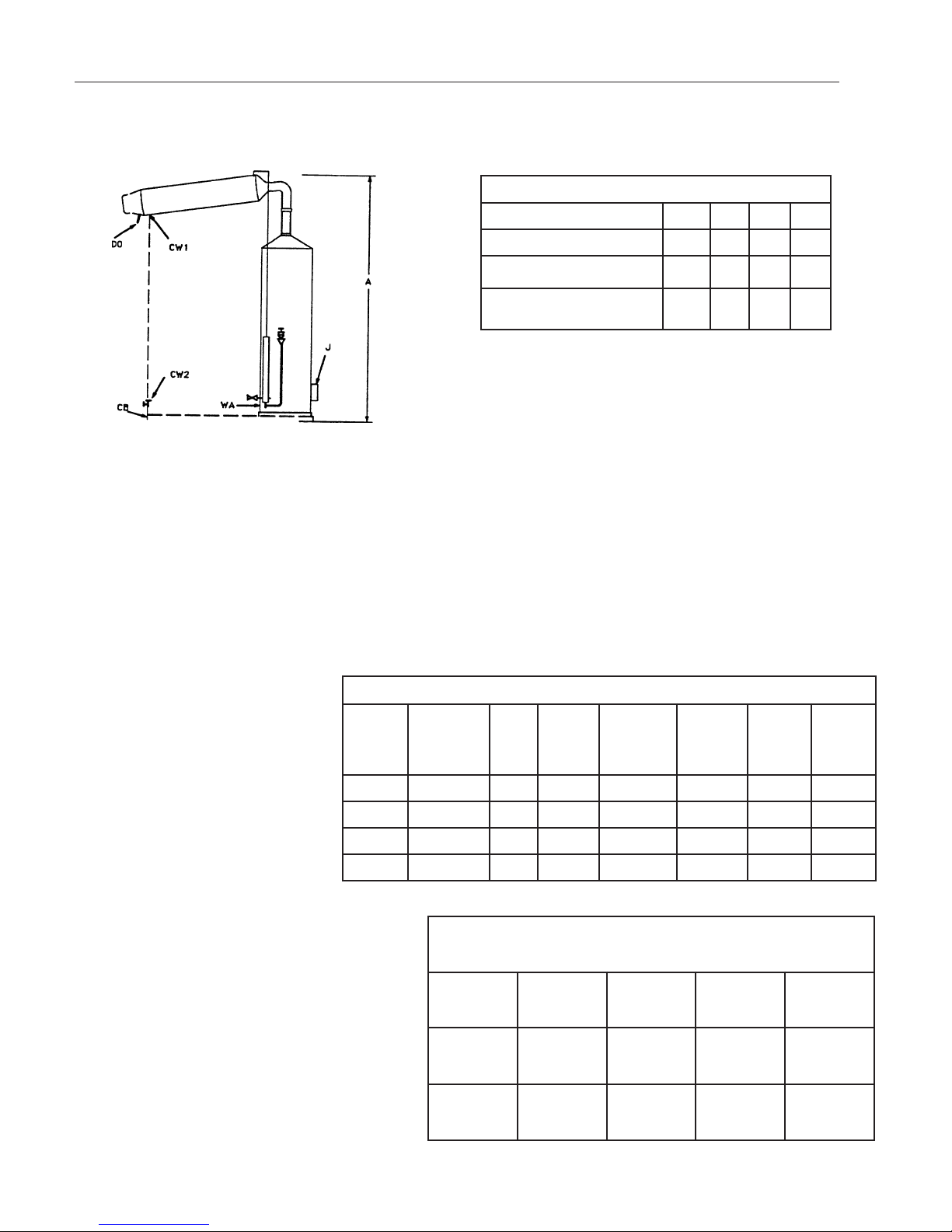
Bench Dimensions in Inches
Electric Heat
Still Cap (GPH) 1 2 5 10
Dimension A* 20 35 45 58
Dimension B 22 23 35 43
Dimension C 10 11 14 14
Figure 2
Top View
* Overall height includes enough
clearance to facilitate condenser
removal.
Note
The still is not designed to sup-
port the service piping. Ensure
that the service piping is ade-
quately supported. If no control
valves were purchased with the
still, a shutoff valve and throt-
tling valve should be installed in
the cooling water supply line,
just before the still.
10
stnemeriuqeRtaeHcirtcelE
ledoM
rebmuN
llitS
yticapaC WK
taspmA
V021
eriW2
esahP1
taspmA
V042/V021
eriW3
esahP1
taspmA
V8o2/021
eriW4
esahP3
taspmA
V042
eriW3
esahP3
taspmA
V084
eriW3
esahP3
1101AHPG16.23221ANANAN
3101AHPG26AN6271ANAN
5101AHPG531AN756333AN
6101AHPG0162ANAN376633
tnemeriuqeRerusserPtelnIdnaretaWgnilooC
llitS
yticapaC HPG1HPG2HPG5HPG01
gnilooC
retaW
tnemeriuqeR
rh/L03
HPG8
rh/L16
HPG61
rh/L151
HPG04
rh/L303
HPG08
retaWtelnI
erusserP
isp09-04
3.6-8.2
mc/gk
2
isp09-04
3.6-8.2
mc/gk
2
isp09-04
3.6-8.2
mc/gk
2
isp09-04
3.6-8.2
mc/gk
2
sehcnIniseziSeniLecivreS
)HPG(yticapaCllitS12501
ylppuSretaWgnilooC-WC4/14/14/18/3
etsaW-AW2/12/14/34/3
gnittifretawdeeftnemtaerterP
)ylnosllitstnemtaerterprof( 8/38/38/38/3
Notes
CW-1: Cooling water inlet connection 1, 2 and GPH
stills (water supply pressure - 40 to 90 psi.)
CW-2: Cooling water inlet connection on 10 GPH still
(water supply pressure - 40 to 90 psi.
CB: Channel base, supplied on 10 GPH stills.
J: Junction box for heating element connections on elec-
trically heated stills.
DO: Distillate outlet.
WA: Waste line must be atmospherically vented and
gravity flow.
Figure 3
Front View
INSTALLATION

11
Electrical Connections
Connect the electrical heating service to the still as
shown in Figure 14. The heating service terminal
board is located inside the junction box at the base
of the still. Customer must supply adequate on-off
control for electrical heating service.
Make the electrical connection to the terminal
board in the low water cutoff control cabinet as
shown in Figure 9 and in accordance with the fol-
lowing instructions:
1. Remove the low water cutoff cabinet front
panel. To remove the panel, remove the
two lower screws in the front of the cabi-
net and press firmly down at the bottom
center of the panel to free the panel from
the cabinet. The panel fits tightly in the
cabinet. Do not attempt to pry the panel
from the cabinet.
2. Connect the low water cutoff probe wires
to terminals 1 and 2 with #18 AWG strand-
ed wire. Connect the outer shield wire of
the probe to terminal #1 and the center
wire of the probe to terminal #2. Solder
and tape the connections. At the evapora-
tor both wires should protrude through the
grommet in the probe shield which is
secured in place with 2 screws over the
cutoff access hole in the evaporator cas-
ing.
3. Connect the still heat control contactor coil
to terminals 6 and 11.
4. Connect a 3-wire, 115-VAC, 60-hertz elec-
trical service to terminals 9 (AC high), 7
(AC low), and the ground screw just below
the terminal board. This electrical service
will provide control voltage for the low
INSTALLATION

12
water cutoff controls and the contactor
coil (see See Figure 9).
5. Connect the heater electrical service
to the contactor (see Figure 9). See
the still wiring diagram when connect-
ing the still heating elements to the
contactor - the heater electrical ser-
vice requirements will be indicated on
the nameplate decal at the base of the
still evaporator.
6. Install the front panel on the low water
cutoff cabinet and install the cover on
the contactor cabinet.
INSTALLATION
13
Initial Startup
The first time that the still is started, or after
cleaning, operate the still as follows:
1. Close the drain valve.
2. Open the deconcentrator valve slightly.
3. Open the cooling water inlet valve.
4. Open the cooling water throttling valve
about 1/2 turn.
5. When water begins to issue steadily
from the deconcentrator valve, turn on
the still heat supply.
6. When the still begins to produce distilled
water, close the deconcentrator valve
and adjust the cooling water throttling
valve until a puff of steam issues from
the condenser vent. Discard the first two
hours production of distillate to allow the
still to clean itself out.
7. Adjust the deconcentrator as described
below.
Initial Operation
The first time the still is operated, or after
cleaning, set the low water cutoff control
“ON/OFF” toggle switch to ON position, open the
manual drain valve and operate the still accord-
ing to the basic still operating instructions. The
lighted switch will remain lit as long as the switch
is in the ON position. The “Still On” lamp will light
when the water in the evaporator makes contact
with the probe. The still is started and stopped
with the “ON/OFF” toggle switch.
Operation
Warning
Afire hazard may result if the
still is used with a flammable liq-
uid. “Caution: Hot Surface. Avoid
Contact.”
Note
During the procedures listed
below, check all connections for
leaks and tighten as required.
Note
The cooling water inlet and
throttling valves are shown in
dotted lines. If these were not
purchased with the still, they
must be installed in the cooling
water inlet line by the customer
to ensure proper operation.
Caution
Ensure that the water level in
the evaporator is above the
heating elements before turning
on the still. The heaters are the
immersion type and will burn out
if operated in air. The water level
should be safe when water
issues steadily from the decon-
centrator valve.
Note
Ideally, the temperature of the
steam and gases escaping the
vent should be 70°C or higher.
To measure the vent
temperature, use a
thermocouple probe, such as
the Thermolyne PM20700
Digital Pyrometer, inserted into
the vent.

14
Deconcentrator Adjustment
The function of the deconcentrator is to maintain
a minimum concentration of dissolved impurities
in the evaporator, thus reducing scale formation
and tendency to foam to a minimum. The decon-
centrator is adjusted as follows:
1. Permanent Hard Water or Softened
Water (Softened feed is not
recommended). The deconcentrator
valve should be left open at all times to
bleed water from the evaporator at ap-
proximately 1-1/2 times the capacity of
the still. This valve should be left open
permanently at the required setting.
Care should be exercised to see that it
is never clogged. The valve should be
inspected periodically and if required,
disassembled and cleaned with a brush
or scraper.
2. Temporary Hard Water. If the feedwater
to the evaporator is high in temporary
hardness, i.e., high in bicarbonates, the
deconcentrator valve should be closed.
The reason for this is that bicarbonates
in solution tend to precipitate out at tem-
peratures exceeding 150°F. With the
deconcentrator valve opened, a larger
quantity of feedwater passes through the
evaporator, precipitating out
bicarbonates, increasing the amount of
scale formed. Keeping the to 150°
deconcentrator closed will result in an in-
creased concentration of solids in the
evaporator as time goes on, thus
creating a tendency to foam. This
condition is corrected by draining the still
through the drain valve at frequent
intervals.
3. Demineralized Water
When demineralized water is used as
feedwater the deconcentrator valve may
be kept closed.
OPERATION

15
Normal Operation
Starting - Start the still as follows:
1. Close the drain valve.
2. Open the deconcentrator valve slightly,
if not adjusted.
3. Open the cooling water inlet valve.
4. When water begins to issue steadily
from the deconcentrator valve, turn on
the still heat supply.
As long as the low water cutoff control “ON/OFF”
toggle switch is in the ON position, the still will
start and stop automatically, depending on the
stored distilled water distribution requirements
and the operating cycle of the interval drain timer.
To stop the still, set the low water cutoff control
“ON/OFF” toggle switch to the OFF position.
When this is done, the still will drain
automatically.
5. If necessary, adjust the cooling water
throttling valve until a puff of steam
issues from the condenser vent.
Stopping - Stop the still as follows:
1. Shut off the still heat supply.
2. Close the cooling water inlet valve.
3. Open the drain valve and let the still
drain completely.
OPERATION
Caution
Ensure that the water level in
the evaporator is above the
heating elements before turning
on the still. The heaters are the
immersion type and will burn out
if operated in air. The water level
should be safe when water
issues steadily from the decon-
centrator valve.
Note
Ideally, the temperature of the
steam and gases escaping the
vent should be 70°C or higher.
To measure the vent
temperature, use a
thermocouple probe, such as
the Thermolyne PM20700
Digital Pyrometer, inserted into
the vent.
Note
Do not change the setting of the
cooling water throttling valve
and deconcentrator valve.

16
Figure 4
Operating Controls
OPERATION
Note
Valves shown in dotted lines
must be installed by customer.
Available as optional equip-
ment.
Condenser
Vent
Distillate
Tube Cooling Water
Throttling Valve
Cooling Water
Inlet Valve
Deconcentrator
Valve
Drain Valve
Electrical Terminal
Connection Box

17
Cleaning Methods
Cleaning requirements fall into two classes, scale
removal and biological cleaning. Scale removal
may be accomplished chemically or mechanical-
ly. Biological cleaning is accomplished with an
isopropyl alcohol solution. For best results all
solutions and water should be heated. The vari-
ous methods of cleaning are described below:
Soft Scale Removal. Soft scale may be re-
moved with a stiff bristle brush. After cleaning, all
scale particles should be flushed out with water.
Hard Scale Removal. Hard scale may be re-
moved by using a 10% solution of inhibited HCI.
This acid cleaner is available commercially or
may be prepared using 20 parts water and 6
parts 30% HCI. When using the acid, do not
allow the acid to remain in contact with the part
for more than 20 minutes. Flush the part thor-
oughly after using the acid cleaner. A 5% Sodium
Bicarbonate solution may be used to remove any
acid left on the part.
Organic Scale and Sludge Removal. If the
scale has a dark brown or black color, it may be
formed from organic impurities present in the
feedwater. This type of scale may be removed
with a strong detergent solution. The detergent
solution should be allowed to be in contact with
the scale or sludge for 24 hours. Rinse off the
parts with water after cleaning.
Silica Scale Removal. Silica scale is usually
clear and shiny and hard to detect visually. It is
very hard and cannot be removed with an acid
solution. Silica scale formation can be reduced
by controlling the quality of the feedwater by rout-
ing it through a mixed bed deionizer. It is best re-
moved with a blunt instrument.
Maintenance and Servicing
Note
If desired, 10% solutions of sul-
famic or acetic acids may be
used instead of the HCI.
Sulfamic and acetic acids have
an advantage over hydrochloric
acid in that they will not corrode
the metal parts being cleaned.
Under no circumstances
should any concentrated acid
be allowed to come in contact
with tinned surfaces.
Warning
Always wear protective clothing
and eye shields when handling
acid. Disconnect from the power
supply prior to maintenance and
servicing. Refer servicing to
qualified personnel.

18
Biological Cleaning. Biological cleaning is used
on the parts that come in contact with the
distillate (such as, the distilled water side of the
condenser, or the distilled water transmission
tubing) to remove any biological contamination
from the affected part. This may be accomplished
as follows:
1. Immerse the part in an isopropyl alcohol
or a mild detergent (not containing
bleach) solution overnight. Do not rinse
the part with water after cleaning. Drain
parts before reassembly.
2. After the still is reassembled and has
operated for 30 minutes to flush, reduce
the cooling water flow rate with the cool-
ing water throttling valve until steam
issues from the condenser vent at least
12 inches. Operate the still in this
manner for 30-60 minutes. Ventilate the
room during this operation.
Disassembly for Cleaning
The frequency of cleaning will depend upon the
purity of the water being used. For example, the
evaporator should require infrequent cleaning if it
is fed partially purified water; however, the
cooling water side of the condenser will have to
be cleaned at more frequent intervals due to the
fact that raw water is flowing through it and it will
scale up sooner. The still should be inspected at
frequent intervals until cleaning intervals are
determined. Disassemble, inspect, and clean the
still as follows:
MAINTENANCE AND SERVICING
Warning
Avoid splashing the isopropyl
alcohol solution on open cuts.
Caution
Do not use chlorine bleach for
biological cleaning. The chlorine
will interact with and damage the
tinned surfaces.

19
1. Shut off and drain the still.
2. Shut off the water supply to the still.
3. Remove the condenser from the still.
Inspect the cooling water side of the
condenser for scale and clean as re-
quired. If required, clean the distilled
water side of the condenser as
described under “Biological Cleaning.”
4. Disassemble until the interior of the
evaporator is visible. The evaporator
cover, high purity chamber and pre-
heater (if supplied) may be removed
as a unit and the interior of the evapo-
rator will be visible. Inspect the interior
of the evaporator for scale. Remove
as much scale as possible manually.
5. Disassemble the drain line and clean
as required. Ensure that the drain line
is clear (including the drain opening in
the evaporator) before using detergent
or acid cleaners. Reassemble the
drain line.
6. Soft scale may be removed as
described under “Soft Scale
Removal.” Silica scale may be re-
moved as described under “Silica
Scale Removal.” To remove hard
scale or organic scale, fill the evapora-
tor with concentrated acid (see “Hard
Scale Removal”) or detergent solution
(see “Organic Scale and Sludge Re-
moval”) or detergent solution (see
“Organic Scale and Sludge Removal”)
as required.
MAINTENANCE AND SERVICING
Note
Stills equipped with a high purity
chamber or preheater should
not be cleaned with acid unless
the high purity chamber can be
removed. The fumes given off
by the acid may damage the tin
coating used in these
accessories.

20
7. Inspect the constant level device and
drain line. Clean as required.
8. If the still is equipped with a gauge
glass, remove and clean the gauge
glass cocks and gauge glass:
a. Unscrew the nuts that hold the gauge
glass in place.
b. Lift the gauge glass up into the top
gauge glass cock about 1/2 inch.
c. After the bottom of the gauge glass is
clear of the bottom gauge glass cock,
move it away from the still and
remove it from the upper gauge glass
cock.
d. Remove and clean the gauge glass
cocks and clean the gauge glass.
9. Reassemble the still. Assembly is
essentially the reverse of disassembly.
10. Connect the water, waste and distillate
lines.
11. Start the still as described under “Initial
Startup.”
12. Lower the cooling water flow rate (with
the cooling water throttling valve) until
steam spouts out of the condenser vent
at least 12 inches. Operate in this
manner for 30-60 minutes to sterilize
and clean out the still.
13. Adjust the still as described in “Initial
Operation.”
MAINTENANCE AND SERVICING
Caution
Ventilate the room during this
operation.
This manual suits for next models
3
Table of contents


 Use & care manual")


 Product summary sheet")


