Bauer Kompressoren SECCANT IV Installer manual
INSTRUCTION MANUAL
AND SPARE PARTS CATALOGUE
BAUER KOMPRESSOREN GmbH
Postfach 710260 D−81452 München Tel. 089/78049−0 Fax 089/78049167
SECCANT IV
SECCANT IV A
HIGH PRESSURE
REGENERATIVE TYPE DRYER
with B−Control Unit

Instruction Manual SECCANT IV
i
INTRODUCTION
This manual contains operating and maintenance instructions for the
high pressure regenerative dryers
All instructions should be observed and carried out in the order laid
down to prevent damage and premature wear to the equipment and
the units served by it. The company voids all warranties for malfunc-
tion and damage resulting from failing to follow these instructions.
All information and illustrations are without obligation −we reserve the
right to make changes to state of the art requirements, in improving
performance, or as required by safety or commercial restrictions.
We are happy to give you advice on any questions regarding your
BAUER unit, and help as soon as possible with any arising problems.
You can contact us Mondays to Thursdays from 0800 till 1630, Fridays
from 0800 till 1400 on phone no. (089) 78049−0.
Calling the following extensions directly will save you time and conti-
nuous dialling.
Do you want to order spare parts?
Customer service
Phone no: (089) 78049−129 or −149
Fax no: (089) 78049−101
Do you have problems with maintenance or repair work?
Technical customer service
Phone no: (089) 78049−246 or −176
Fax no: (089) 78049−101
Do you need further information regarding your unit, accessories, pri-
ces etc.?
Sales department
Phone no: (089) 78049−138, −185, −154, −205 or −202
Fax no: (089) 78049−103
Are you interested in any training courses?
Training manager
Phone no: (089) 78049−175
Fax no: (089) 78049−103
Or visit us in the internet at:
www.bauer−kompressoren.de
Edition June 2005
2005 BAUER Kompressoren GmbH, München
All rights reserved
SECCANT IV
SECCANT IV A

Instruction Manual SECCANT IV
ii
TABLE OF CONTENTS
1. GENERAL 1. . . . . . . . . . . . . . . . . . . . . . . . . . . . . . . . . . . . . . . . . . . . . . . . . . . . . . . . . . . . . . . . . . . . . . . . . . . . . . . . . . . . . . . . . . . . . . . . .
2. FUNCTION 5. . . . . . . . . . . . . . . . . . . . . . . . . . . . . . . . . . . . . . . . . . . . . . . . . . . . . . . . . . . . . . . . . . . . . . . . . . . . . . . . . . . . . . . . . . . . . . . . .
3. INSTALLATION, OPERATION 17. . . . . . . . . . . . . . . . . . . . . . . . . . . . . . . . . . . . . . . . . . . . . . . . . . . . . . . . . . . . . . . . . . . . . . . . . . . . . . . .
4. INSPECTION AND MAINTENANCE 18. . . . . . . . . . . . . . . . . . . . . . . . . . . . . . . . . . . . . . . . . . . . . . . . . . . . . . . . . . . . . . . . . . . . . . . . . . .
5. TROUBLE−SHOOTING 22. . . . . . . . . . . . . . . . . . . . . . . . . . . . . . . . . . . . . . . . . . . . . . . . . . . . . . . . . . . . . . . . . . . . . . . . . . . . . . . . . . . . . .
6. ANNEX 23. . . . . . . . . . . . . . . . . . . . . . . . . . . . . . . . . . . . . . . . . . . . . . . . . . . . . . . . . . . . . . . . . . . . . . . . . . . . . . . . . . . . . . . . . . . . . . . . . . . .
TABLE OF FIGURES
Fig. 1 High pressure regenerative dryer SECCANT IV 1. . . . . . . . . . . . . . . . . . . . . . . . . . . . . . . . . . . . . . . . . . . . . . . . . . . . . . . . . . . . . . . . . .
Fig. 2 SECCANT IV, regenerative dryer design 2. . . . . . . . . . . . . . . . . . . . . . . . . . . . . . . . . . . . . . . . . . . . . . . . . . . . . . . . . . . . . . . . . . . . . . . .
Fig. 3 SECCANT IV A, regenerative dryer design 3. . . . . . . . . . . . . . . . . . . . . . . . . . . . . . . . . . . . . . . . . . . . . . . . . . . . . . . . . . . . . . . . . . . . . .
Fig. 4 Standard flow diagram, example SECCANT IV 7. . . . . . . . . . . . . . . . . . . . . . . . . . . . . . . . . . . . . . . . . . . . . . . . . . . . . . . . . . . . . . . . . . .
Fig. 5 Controls and monitors 8. . . . . . . . . . . . . . . . . . . . . . . . . . . . . . . . . . . . . . . . . . . . . . . . . . . . . . . . . . . . . . . . . . . . . . . . . . . . . . . . . . . . . . . .
Fig. 6 Start page 9. . . . . . . . . . . . . . . . . . . . . . . . . . . . . . . . . . . . . . . . . . . . . . . . . . . . . . . . . . . . . . . . . . . . . . . . . . . . . . . . . . . . . . . . . . . . . . . . . .
Fig. 7 Actual values page I 9. . . . . . . . . . . . . . . . . . . . . . . . . . . . . . . . . . . . . . . . . . . . . . . . . . . . . . . . . . . . . . . . . . . . . . . . . . . . . . . . . . . . . . . . .
Fig. 8 Main menu page 9. . . . . . . . . . . . . . . . . . . . . . . . . . . . . . . . . . . . . . . . . . . . . . . . . . . . . . . . . . . . . . . . . . . . . . . . . . . . . . . . . . . . . . . . . . . .
Fig. 9 Maintenance menu 9. . . . . . . . . . . . . . . . . . . . . . . . . . . . . . . . . . . . . . . . . . . . . . . . . . . . . . . . . . . . . . . . . . . . . . . . . . . . . . . . . . . . . . . . . .
Fig. 10 Operation menue 10. . . . . . . . . . . . . . . . . . . . . . . . . . . . . . . . . . . . . . . . . . . . . . . . . . . . . . . . . . . . . . . . . . . . . . . . . . . . . . . . . . . . . . . . . . . .
Fig. 11 Operation modes 10. . . . . . . . . . . . . . . . . . . . . . . . . . . . . . . . . . . . . . . . . . . . . . . . . . . . . . . . . . . . . . . . . . . . . . . . . . . . . . . . . . . . . . . . . . . .
Fig. 12 Filter parameters 11. . . . . . . . . . . . . . . . . . . . . . . . . . . . . . . . . . . . . . . . . . . . . . . . . . . . . . . . . . . . . . . . . . . . . . . . . . . . . . . . . . . . . . . . . . . .
Fig. 13 Condensate drain valve parameters 11. . . . . . . . . . . . . . . . . . . . . . . . . . . . . . . . . . . . . . . . . . . . . . . . . . . . . . . . . . . . . . . . . . . . . . . . . . . .
Fig. 14 Pressure units 11. . . . . . . . . . . . . . . . . . . . . . . . . . . . . . . . . . . . . . . . . . . . . . . . . . . . . . . . . . . . . . . . . . . . . . . . . . . . . . . . . . . . . . . . . . . . . .
Fig. 15 Language selection 11. . . . . . . . . . . . . . . . . . . . . . . . . . . . . . . . . . . . . . . . . . . . . . . . . . . . . . . . . . . . . . . . . . . . . . . . . . . . . . . . . . . . . . . . . .
Fig. 16 Maintenance data page 12. . . . . . . . . . . . . . . . . . . . . . . . . . . . . . . . . . . . . . . . . . . . . . . . . . . . . . . . . . . . . . . . . . . . . . . . . . . . . . . . . . . . . . .
Fig. 17 Main service data page 12. . . . . . . . . . . . . . . . . . . . . . . . . . . . . . . . . . . . . . . . . . . . . . . . . . . . . . . . . . . . . . . . . . . . . . . . . . . . . . . . . . . . . . .
Fig. 18 Dryer cartridge service data page 12. . . . . . . . . . . . . . . . . . . . . . . . . . . . . . . . . . . . . . . . . . . . . . . . . . . . . . . . . . . . . . . . . . . . . . . . . . . . . .
Fig. 19 Activated carbon cartridge data page 12. . . . . . . . . . . . . . . . . . . . . . . . . . . . . . . . . . . . . . . . . . . . . . . . . . . . . . . . . . . . . . . . . . . . . . . . . . .
Fig. 20 Filter housing service data page 13. . . . . . . . . . . . . . . . . . . . . . . . . . . . . . . . . . . . . . . . . . . . . . . . . . . . . . . . . . . . . . . . . . . . . . . . . . . . . . .
Fig. 21 Final separator service data page 13. . . . . . . . . . . . . . . . . . . . . . . . . . . . . . . . . . . . . . . . . . . . . . . . . . . . . . . . . . . . . . . . . . . . . . . . . . . . . .
Fig. 22 Logbook page 13. . . . . . . . . . . . . . . . . . . . . . . . . . . . . . . . . . . . . . . . . . . . . . . . . . . . . . . . . . . . . . . . . . . . . . . . . . . . . . . . . . . . . . . . . . . . . . .
Fig. 23 Logbook page 13. . . . . . . . . . . . . . . . . . . . . . . . . . . . . . . . . . . . . . . . . . . . . . . . . . . . . . . . . . . . . . . . . . . . . . . . . . . . . . . . . . . . . . . . . . . . . . .
Fig. 24 Configuration page 14. . . . . . . . . . . . . . . . . . . . . . . . . . . . . . . . . . . . . . . . . . . . . . . . . . . . . . . . . . . . . . . . . . . . . . . . . . . . . . . . . . . . . . . . . . .
Fig. 25 Sensor setting page 14. . . . . . . . . . . . . . . . . . . . . . . . . . . . . . . . . . . . . . . . . . . . . . . . . . . . . . . . . . . . . . . . . . . . . . . . . . . . . . . . . . . . . . . . . .
Fig. 26 Sensor limits page 14. . . . . . . . . . . . . . . . . . . . . . . . . . . . . . . . . . . . . . . . . . . . . . . . . . . . . . . . . . . . . . . . . . . . . . . . . . . . . . . . . . . . . . . . . . .
Fig. 27 Filter for logbook 14. . . . . . . . . . . . . . . . . . . . . . . . . . . . . . . . . . . . . . . . . . . . . . . . . . . . . . . . . . . . . . . . . . . . . . . . . . . . . . . . . . . . . . . . . . . .
Fig. 28 Control voltage transformer 15. . . . . . . . . . . . . . . . . . . . . . . . . . . . . . . . . . . . . . . . . . . . . . . . . . . . . . . . . . . . . . . . . . . . . . . . . . . . . . . . . . .
Fig. 29 Installation diagram 17. . . . . . . . . . . . . . . . . . . . . . . . . . . . . . . . . . . . . . . . . . . . . . . . . . . . . . . . . . . . . . . . . . . . . . . . . . . . . . . . . . . . . . . . . .
Fig. 30 Cartridge change 19. . . . . . . . . . . . . . . . . . . . . . . . . . . . . . . . . . . . . . . . . . . . . . . . . . . . . . . . . . . . . . . . . . . . . . . . . . . . . . . . . . . . . . . . . . . .
Fig. 31 Oil and water separator 20. . . . . . . . . . . . . . . . . . . . . . . . . . . . . . . . . . . . . . . . . . . . . . . . . . . . . . . . . . . . . . . . . . . . . . . . . . . . . . . . . . . . . . .
Fig. 32 Particle filter 21. . . . . . . . . . . . . . . . . . . . . . . . . . . . . . . . . . . . . . . . . . . . . . . . . . . . . . . . . . . . . . . . . . . . . . . . . . . . . . . . . . . . . . . . . . . . . . . .
Instruction Manual SECCANT IV
iii
ANNEX
Flow diagram
Seccant IV/IV−A−350 bar 76936*
Seccant IV/IV−A−420 bar 90965*
Seccant IV/IV−AH−350 bar (helium version) 82727−01 + 82727−02*
Drawing of regenerative dryer
Plan de construction SECCANT IV/IV A 81983
Plan de construction SECCANT IV/IV A−420 bar 82828
Schematic diagrams:
100 −127 V 82948*
220 −240 V 82949*
Applicable parts list: Code
SECCANT IV, SECCANT IV A (air) G25
SECCANT IV, SECCANT IV A (gas) G29
Change notice
Change No. Change date
1. Basic edition July 1996
2. January 2003
3. August 2004
4. June 2005
*) or according to order
Instruction Manual SECCANT IV
iv
Instruction Manual SECCANT IV
1
1. GENERAL
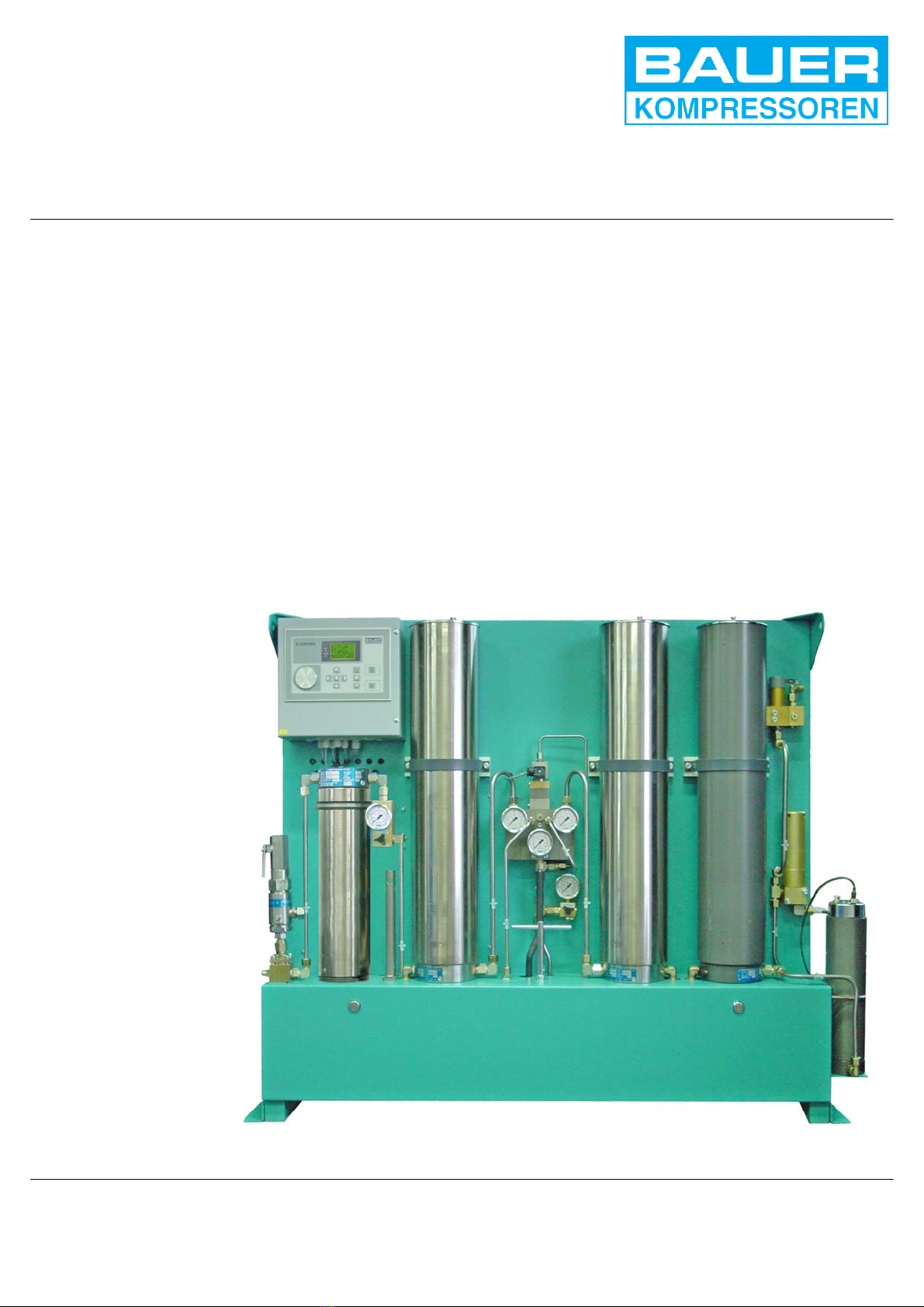
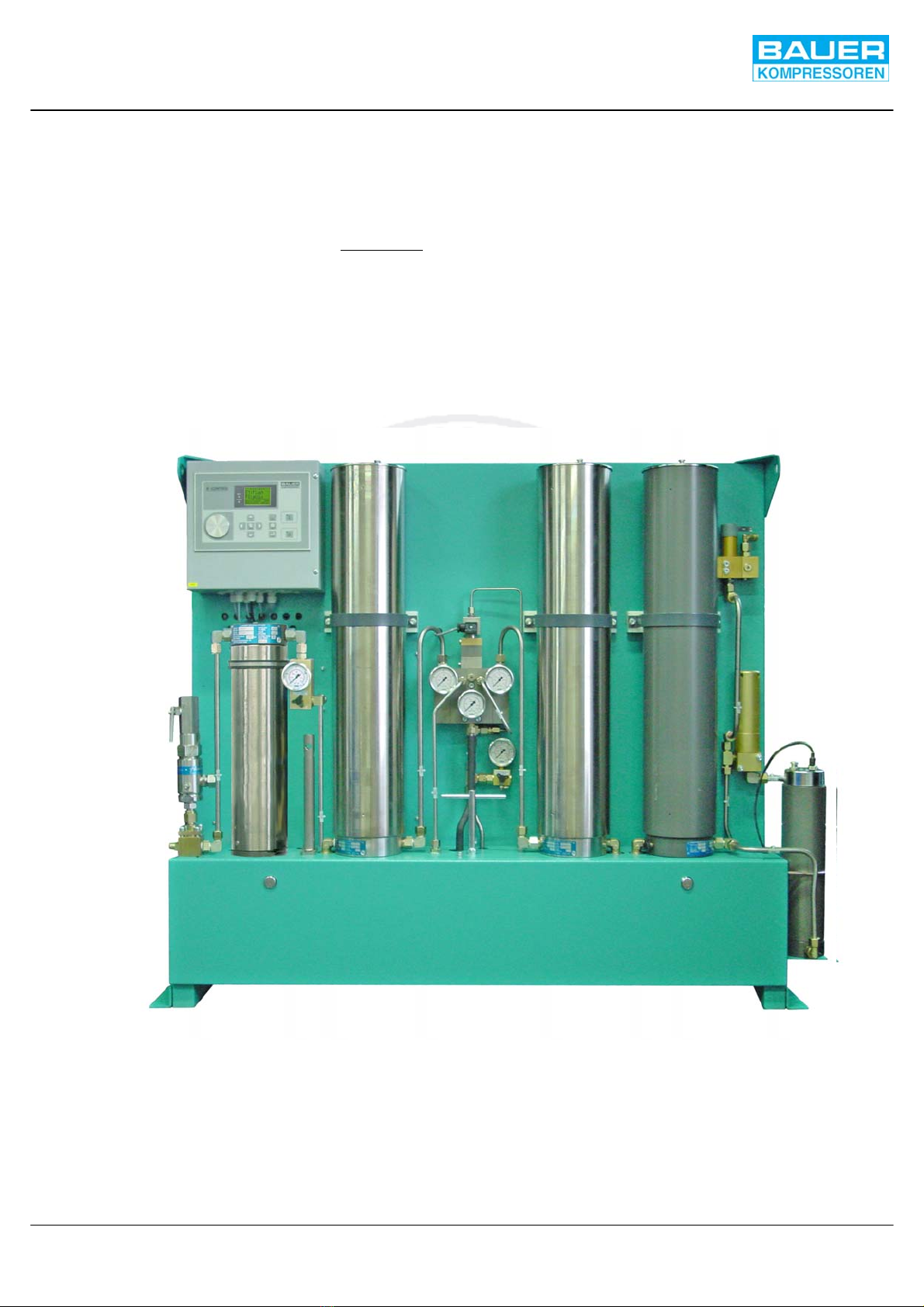
APPLICATION AND SHORT DESCRIPTION
The regenerative dryers of the SECCANT series are used for
automatic drying of compressed air and non−explosive gases.
A significant feature of this series is the simultaneous occur-
rence of drying phase and regeneration phase during one oper-
ating cycle: as one filter dries the compressed medium, the
other is being regenerated. This ensures continuous and effec-
tive operation.
To avoid excessive wear of the filter fillings, the SECCANT dry-
ers are equipped with a pressure compensation system which
ensures a slow and gentle pressurization when switching from
regeneration phase (low pressure) to drying phase (high pres-
sure).
Regenerative dryers which are used for drying gases, are
equipped with a gas feed−back system which leads the regen-
eration and the control gas back to the compressor intake (see
flow diagram in the annex).
Fig. 1 High pressure regenerative dryer SECCANT IV

Instruction Manual SECCANT IV
2
DESIGN
For all mentioned parts and numbers refer to dryer design SEC-
CANT IV, Fig. 2 and SECCANT IV A, Fig. 3.
The regenerative dryer consists of two filters (1 and 2), which
are equipped with replaceable cartridges. The cartridges are
filled with a highly porous dehydrating agent (molecular sieve).
Upstream of the drying and regenerating system, an oil and wa-
ter separator (23) should be mounted. It absorbs any fluid oil
and water particles out of the pressurized air or gas from the
compressor. Safety valve (25) protects the pressure system
from excessive pressure.
The non−return valve with gauge and venting valve (22) which
is situated downstream from the oil and water separator pre-
vents the dried medium from flowing back to the separator when
draining condensate.
For breathing air processing, a final purifier (27, Fig. 3) should
be placed downstream of the drying and regenerating filters. It
is equipped with a filter cartridge with activated charcoal which
removes residual oil vapours and makes the air tasteless and
odourless as required for breathing air quality. The final purifier
can also be installed in industrial air or gas dryers if air or gas
of the purest quality is required.
A discharge valve with pressure gauge (28) is placed down-
stream of the valve block.
4
5
6
7
1 Drying filter
2 Drying filter
3 Control unit
4 3/2−way solenoid valve, pressure comp.
5 Pressure compensation valve
6 Pressure gauge, regeneration pressure
7 Pressure gauge, operating pressure
8 Pressure maintaining/non−return valve
9 Air/gas outlet
10 Regulating valve
11 Safety valve, 14 bar
12 Pressure reducer
13 4/2−way solenoid valve,
drying/regeneration phase
14 Switch−over valve,
drying/regeneration phase
15 Pneumatic actuator
16 3/2−way solenoid valve, shut−off
17 Shut−off valve
18 Control/regeneration air/gas outlet
19 Air/gas inlet
20 Condensate drain valve
21 3/2−way solenoid valve, condensate drain
22 Non−return valve with pressure gauge
and venting valve
23 Oil and water separator
24 Particle filter
25 Safety valve, final pressure
26 Feed back manifold (only gas models)
27 Manual condensate drain tap
28 Discharge valve with pressure gauge
Fig. 2 SECCANT IV, regenerative dryer designa)
a) to ensure clarity, piping is not shown

Instruction Manual SECCANT IV
3
4
5
6
7
1 Drying filter
2 Drying filter
3 Control unit
4 3/2−way solenoid valve, pressure comp.
5 Pressure compensation valve
6 Pressure gauge, regeneration pressure
7 Pressure gauge, operating pressure
8 Pressure maintaining/non−return valve
9 Air/gas outlet
10 Regulating valve
11 Safety valve, 14 bar
12 Pressure reducer
13 4/2−way solenoid valve,
drying/regeneration phase
14 Switch−over valve,
drying/regeneration phase
15 Pneumatic actuator
16 3/2−way solenoid valve, shut−off
17 Shut−off valve
18 Control/regeneration air/gas outlet
19 Air/gas inlet
20 Condensate drain valve
21 3/2−way solenoid valve, condensate drain
22 Non−return valve with pressure gauge
and venting valve
23 Oil and water separator
24 Particle filter
25 Safety valve, final pressure
26 Feed back manifold
27 Final purifier
28 Discharge valve with pressure gauge
29 Manual condensate drain tap
Fig. 3 SECCANT IV A, regenerative dryer designa)
Particle filter (24) is placed downstream of the drying and regen-
erating filters/the final purifier. After the filters, a pressure re-
ducer (12) is connected into the line. It provides the air or gas
that is needed to control the regenerating and switch−over pro-
cedures, the pressure compensation and the automatic con-
densate drain.
After the pressure reducer, within the regeneration circuit, a
safety valve (11) and a regulating valve (10) are situated. The
regulating valve regulates the amount of regenerative air or gas
supplied according to its setting.
The regeneration dryer is also equipped with a switch−over
valve (14), controlled by solenoid valve (13) and pneumatic ac-
tuator (15), which switches to and from the regenerating and
drying process.
Pressure compensation valve (5), controlled by solenoid valve
(4) makes sure that before switching over from regenerating to
drying phase, a compensation of pressure takes place in the re-
generating filter.
The operating pressure is indicated by pressure gauge (7).
The regenerating pressure is indicated by pressure gauge (6).
A combined pressure maintaining/non−return valve (8) is
placed at the gas and/or air outlet (9) of the regenerative dryer,
which keeps the pressure at the set minimum.
a) to ensure clarity, piping is not shown

Instruction Manual SECCANT IV
4
TECHNICAL DATA
Operating pressure, max. (Setting pressure of safety valve) 90 −350 bar (2,175 −5,000 psi)
Flow rate at 200 bar 1500−3500 l/min. (53 −124 c.f.m.)
Regeneration volume related to 1 bar absolute (equiv. to 5% of delivery) 75 −175 l/min. (2.65 −6.6.2 c.f.m.)
Intake temperature, max. +50 C (122 F)
Intake temperature, min. + 5 C (41 F)
Ambient temperature + 5 C...+ 40 C (41 F ...113 F)
Pneumatic intake and outlet connections, tube diameter 12 mm
Power consumption 0.02 kWh
Pressure dew point of dried medium −20 C (−4 F)
Length (mm) 1545
height (mm) 1285
Width(mm) 260
Operating voltages 24 VAC, 50/60 Hz
100 VAC, 50/60 Hz
110 VAC, 50/60 Hz
115 VAC, 50/60 Hz
120 VAC, 50/60 Hz
127 VAC, 50/60 Hz
220 VAC, 50/60 Hz
230 VAC, 50/60 Hz
240 VAC, 50/60 Hz
250 VAC, 50/60 Hz
3800 VAC, 50/60 Hz
400 VAC, 50/60 Hz
415 VAC, 50/60 Hz
440 VAC, 50/60 Hz
Subject to change without prior notice
Instruction Manual SECCANT IV
5
2. FUNCTION
The following position numbers refer to stan-
dard air flow diagram SECCANT IV, Fig. 4. For
detailed information, also see air flow dia-
gram corresponding to your dryer type in the
annex.
DRYING CIRCUIT
Both filters of the dryer (1 and 2) are passed through alternately
by humid, compressed medium applied from the compressor,
and by already dried, expanded medium for regeneration.
Non−return valves (3 and 4) are built into the drying circuit and
non−return valves (5 and 6) are built into the regeneration cir-
cuit. They prevent the medium from flowing back into the filters
as well as overstream of high pressure medium into the depres-
surized filter which is in the regeneration process.
The humid medium coming from the compressor flows through
4−way switch−over valve (7) to drying filter (1). The switch−over
valve is operated by pneumatic actuator (8). The desiccant con-
tained in the dryer cartridge absorbs the humidity from the com-
pressed medium.
Non−return valve (4) prevents the air from flowing over to the
depressurized regeneration filter.
Through non−return valve (3), discharge valve with pressure
gauge (28), particle filter (9) and pressure maintaining/non−re-
turn valve (10) the compressed, and now dry and clean medium
flows to the consuming devices.
The dryer operating pressure is indicated at pressure gauge
(29).
The drying phase is coupled to the operation of the compressor.
When shutting off the compressor, 3/2−way solenoid valve (16)
closes, so do the shut−off valves (14) and (15). The SECCANT
unit is then hermetically sealed to prevent loading of the car-
tridge with ambient humidity. On restarting the compressor the
drying phase will be reassumed where it was interrupted and
will continue until the process is switched over by the timer.
REGENERATION CIRCUIT
Drying phase and regenerating phase occur simultaneously
during one cycle, i. e. while the drying phase is taking place in
filter (1), as shown in flow diagram Fig. 4, the regeneration
phase is taking place in filter (2). For that purpose a small
amount of the compressed and dried medium is deviated after
particle filter (9) and expanded by pressure reducer (11) to
approx. 10 bar (145 psi). This pressure is monitored by safety
valve (12).
Through regulating valve (13) and non−return valve (5) the re-
generative medium flows to filter (2). The desiccant moisturized
during the previous drying phase transfers the humidity to the
dry, depressurized medium, and will thus be regenerated.
The flow rate of the regenerative medium depends on the ad-
justment of regulating valve (13). It is set at the required value
in the factory. Should the setting have been changed for some
reason, the regeneration air or gas flow must be re−adjusted by
our technical service. For the flow rate refer to Technical Data
in chapter 2.
Non−return valve (6) prevents high pressure air or gas coming
from drying filter from entering the regeneration circuit. Pres-
sure gauge (27) indicates the pressure in the regenerated filter.
After the regeneration medium has dried the cartridge, it passes
through 4−way change−over valve (7), and shut−off valves (14)
and (15) into the open air or to the compressor intake.
PESSURE COMPENSATION
Regeneration is performed at atmospheric pressure. When
switching from regeneration to drying phase, abruptly loading
the filter with the highly compressed medium coming from the
compressor at up to 350 bar (5,000 psi) must be avoided. This
would cause excessive wear or even destruction of the molecu-
lar sieve filter filling and the cartridge. For this reason, the dryer
is equipped with a pressure compensation system.
At the end of the regeneration phase, i.e. every 15 minutes,
pressure compensation valve (18) opens by applied control air
from 3/2−way solenoid valve (17). At the same time, shut−off
valves (14) and (15) receive control medium from 3/2−way sole-
noid valve (16) and close to avoid regenerative medium from
escaping into the open air/to the compressor intake.
A certain quantity of the medium, which is determined by nozzle
(19), now flows over non−return valve (31) into the regenerated
filter until the pressure inside the two filters is compensated. Af-
ter 80 seconds, pressure compensation valve (18) closes
again, a 3/2−way solenoid valve (16) opens shut−off valves
(14) and (15). Switch−over by valve (7) can now take place.
SWITCH−OVER
After a predetermined time interval, e.g. 15 minutes, 4−way
switch−over valve (7) changes state. The compressed medium
produced by the compressor unit will now be dried in dryer cylin-
der (2, previously regenerated) while the regeneration of the de-
hydrating agent takes place in cylinder (1, previously loaded
with moisture by drying). Cycle switching, i. e. status change of
4−way switch−over valve (7), is performed automatically by
4/2−way solenoid valve (30) activating pneumatic actuator (8).
Pressure gauge (27) now monitors the operating pressure.
CONDENSATE DRAIN
The condensate resulting from the cooling of the compressed
medium is drained automatically. Every 15 minutes, 3/2 way so-
lenoid valve (22) applies control pressure to condensate drain
valve (23) and the condensate is purged via condensate drain
valve (23) and nozzle (24). The condensate can also be drained
manually using tap (25) which is used to check the function of
the automatic drain device. Refer to maintenance procedures
in chapter 6.
Non−return valve with pressure gauge and venting valve (26)
prevents already dried air/gas from flowing back to the separa-
tor when the condensate is drained.
CAUTION
Disposal of condensate according to applicable lo-
cal regulations; (in Germany: special waste dispo-
sal no. 54405).

Instruction Manual SECCANT IV
6
PNEUMATIC CONTROL
The air or gas needed to regenerate the filter and to control the
pressure compensation, the switch−over and the condensate
drain, is regulated by pressure reducer (11). The pressure is
approx. 10 bar.
Regeneration
The air or gas needed for regeneration flows through regulating
valve (13) and non−return valve (5) into the regenerating filter
where it absorbs the humidity in the drying agent. Then it flows
through switch−over valve (7) and open shut−off valves (14)
and (15) into the open air or to the compressor intake (optional
for gas compressors). The shut−off valves are controlled pneu-
matically by the 3/2 way solenoid valve (16).
Pressure compensation
Every 15 minutes, 3/2−way solenoid valves (17, n.o.) and (16,
n.c.) are activated for approx. 80 seconds: solenoid valve (17)
receives an electrical impulse, closes and interrupts the flow of
control medium to pressure compensation valve (18), which
opens then. Solenoid valve (16) receives no electrical im-
pulses, closes and interrupts the flow of control medium to
shut−off valves (14) and (15) which also close.
Switch−over
Immediately after pressure compensation, 4/2−way solenoid
valve (30) receives an electrical impulse and opens.
Depending on the position of the 4/2−way solenoid valve, the
control air or gas flows either to the right or to the left chamber
of pneumatic actuator (8). The chamber is put under pressure
and so switch−over valve (7) is actuated.
Condensate drain
Every 15 minutes 3/2−way solenoid valve of automatic conden-
sate drain (22) receives an electrical impulse and opens. The
control medium now flows to condensate drain valve (23),
which also opens.
When drying gas, the control medium flows from solenoid
valves (16), (17), (22) and (30) to the intake tube of the com-
pressor.
Instruction Manual SECCANT IV
7
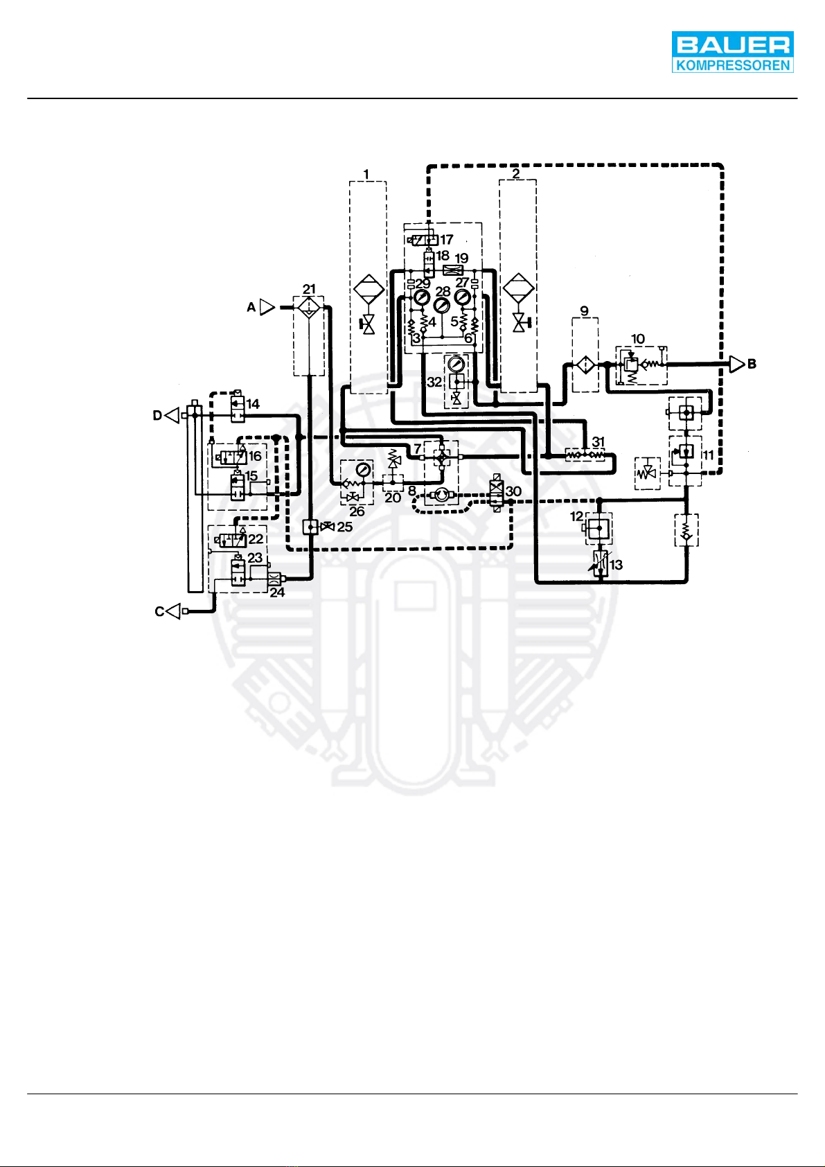
FLOW DIAGRAM
A= Inlet
B= Outlet
C= Condensate outlet
D= Regeneration outlet
Fig. 4 Standard flow diagram, example SECCANT IV
1 High pressure filter
2 High pressure filter
3 Non−return valve
4 Non−return valve
5 Non−return valve
6 Non−return valve
7 Switch−over valve
8 Pneumatic actuator
9 Particle filter
10 Pressure maintaining/non−return valve
11 Pressure reducer
12 Safety valve 14 bar, control pressure
13 Regulating valve
14 Shut−off valve
15 Shut−off valve
16 3/2−way solenoid valve for shut−off valves
17 3/2−way solenoid valve for pressure compensation
18 Pressure compensation valve
19 Nozzle
20 Safety valve, final pressure
21 Oil and water separatorb)
22 3/2−way solenoid valve
23 Condensate drain valve
24 Nozzle
25 Manual drain tap
26 Non−return valve with pressure gauge
and venting valve
27 Pressure gauge, operating pressure
28 Pressure gauge, regenerating pressure
29 Pressure gauge, operating pressure
30 4/2−way solenoid valve
31 Non−return valve
32 Discharge valve with pressure gauge
b) Optional extra

Instruction Manual SECCANT IV
8
B−CONTROL UNIT
GENERAL
BAUER B−CONTROL is a free−programmable electronic
compressor control system with a modern display. The control
system is specially designed for BAUER units, and can be set
and configured for all BAUER models.
HARDWARE AND CONNECTIONS
For reference to the hardware and connections refer to the
respective schematic diagram in the annex.
−Power supply for the unit is connected to terminal strip
X0/F1, 1 and PE. According to the supply voltage, the power
is connected to the respective connection at transformer
T1.
−Collective warning signal from the SECCANT dryer to a
max. number of 3 compressors is at terminals X0/2 to X0/7.
−Operating status signal from a max. number of 3 compres-
sors to the SECCANT dryer is from terminals X0/9 to X0/14.
CONFIGURATION DATA
The configuration of the software with respect to the hardware
is performed in the configuration file. This file is automatically
generated at factory start−up, and normally does not need any
further modification. If a change should become necessary due
to modifications on the unit, please contact the BAUER
after−sales service dept.
CONTROL AND MONITORING ELEMENTS
The control and monitoring panel features a display, 2 indicating
lamps (LED’s), as well as 10 soft touch keys to control the
compressor and the display.
The function of the control keys is as follows:
OShuts the compressor off. On a higher menu level,
returns you to the main menu.
IStarts the compressor, provided there are no failure
messages present or maintenance work due. On a
higher menu level, returns you to the main menu.
Moves the cursor up. If already in the top line, jumps
to the bottom line.
Moves the cursor down. If already in the bottom line,
jumps to the top line.
Decreases a selected value. Press and hold will
decrease the value increasingly faster.
Increases a selected value. Press and hold will
increase the value increasingly faster.
menu change to the next page of the same menu level
enter accept the new value and refresh page
reset change to next higher menu level without storing the
changed values.
code combination key to start initialization routines
(setting “restore defaults” in combination with reset
key).
General notes on the use of the keys
Please do not be impatient. Allow some seconds for the
windows to build up, the time will depend on the amount of
information. In the meantime, please do not press any keys,
even if you know how to proceed.
The red and yellow LED’s next to the display indicate fault and
warning messages. The details for the message are shown on
the display. The red LED indicates a compressor failure, and the
unit will be shut down automatically. The yellow LED indicates
a warning, e.g. imminent maintenance work, the compressor
will not be shut down.
For new faults or warnings the respective LED will flash quickly
until the message is acknowledged with the “reset” key. If the
message is still present after pressing the reset key, the LED will
change to slow flashing, and would extinguish if the cause of the
message would not be present any more. After that, the
compressor can be switched on again.
Fig. 5 Controls and monitors
1
23
4
5
6
7
8
9
1 Alarm indicator (Shut−off)
2 Warning indicator
3 8 line, 21 char. display
4ON−key with indicator
5 OFF key with indicator
6 Code key
7 Reset key
8 Enter key
9 Cursor keys with menu key in the centre
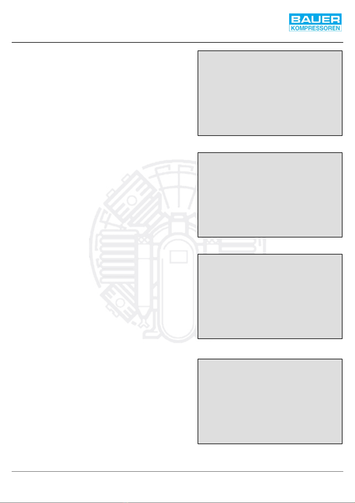
Fig. 6 Start page
S E C C A N T
F1: flush
F2: activ
---TIMER OPERATION---
Dewpointsensor -31 °C
Operation-h 6893 h
Fig. 7 Actual values page I
** ACTUAL VALUES I **
rem. time: 15 min
dew point: -32 °C
securus: ok
Contr.pres: -1 bar
--- bar
DIN start:
CAN start: OFF
Fig. 8 Main menu page
**** MAIN MENU ****
OPERATION . . . . . . . . . . .
MAINTENANCE . . . . . . . . . .
CONFIGURATION . . . . . . . . .
_ _ _ _ _ _ _ _ _ _ _ _ _ _ _ _
AB4321-9876 [S1.00.G]
Fig. 9 Maintenance menu
**** MAINTENANCE ****
Main service ok
Dryer cartridge ok
Act. carbon cart. ok
Filter housing ok
Final separator ok
Logbook 20 R
[2368 h]
Instruction Manual SECCANT IV
9
MENU AND NAVIGATION
The 8−line, 21−digit display contains all the important
information on the present condition of your BAUER unit.
Normally, the start page is displayed which shows the most
important general data in a very clear presentation. This way
you can find out the actual unit status.
According to the operating requirements the menu is split into
four levels:
Level 0: Main page and survey
Level 1: Operation level
Level 2: Maintenance level
Level 3: Configuration level
Each menu level again consists of several windows or pages
which can be paged through comfortably, finally leading back
to the start page (roundabout system). In all higher levels
consisting of a larger number of pages, direct access to the
desired pages from the select menu is possible.
Due to different access codes, changing between operation,
maintenance, and config levels is allowed only from the main
menu. Within one level, you have free movement without being
asked for an access code again. If a higher level has been
accessed by entering the required code, the yellow LED will
start flashing slowly to indicate that you are staying in a
protected area.
The following describes the pages in each level.
LEVEL 0: START PAGE AND SURVEYS
This level consists of four windows or pages giving a quick
survey on the status of your BAUER unit. At unit start, and also
when a signal is received the following page will be displayed
showing the most important data at a glance.
By pressing the menu key repeatedly, the following three pages
of this level are displayed in the order shown below.
By each pressing of the reset key the respective previous page
will be shown, until finally the main page is reached again.
At the bottom of the main menu page you find the data important
and required by the BAUER service dept. At the left you find the
serial no. of the unit unit, at the right in brackets the installed
software version.
From the maintenance page pressing the menu key will get you
back to the start page, pressing the reset key takes you back
to the Main Menu page.
HIGHER MENU LEVEL BRANCHING AND CODE REQUEST
In order to divert into the next higher menu level you have to
select the Main Menu page (Fig. 8). Select the desired level
using the and keys and press enter key.
Before you can select pages at this level, you are requested to
enter the access code. There are different codes for each level
which cannot be overridden.
As long as the unit is operating, access to the adjustments of the
maintenance and configuration levels is disabled. A respective
note will show up in the code window and the display will
automatically change back to the main menu page.
Different from the legend to Fig. 5 the cursor (i.e. the highlighted
figure) will move to the left or right using the or key,
respectively. With the and keys the highlighted value
can be increased or decreased by one. By finishing the code
input with the enter key, you will get access to the selected level.
If a wrong code should have been entered, a respective note
will be displayed, then the menu returns automatically to the
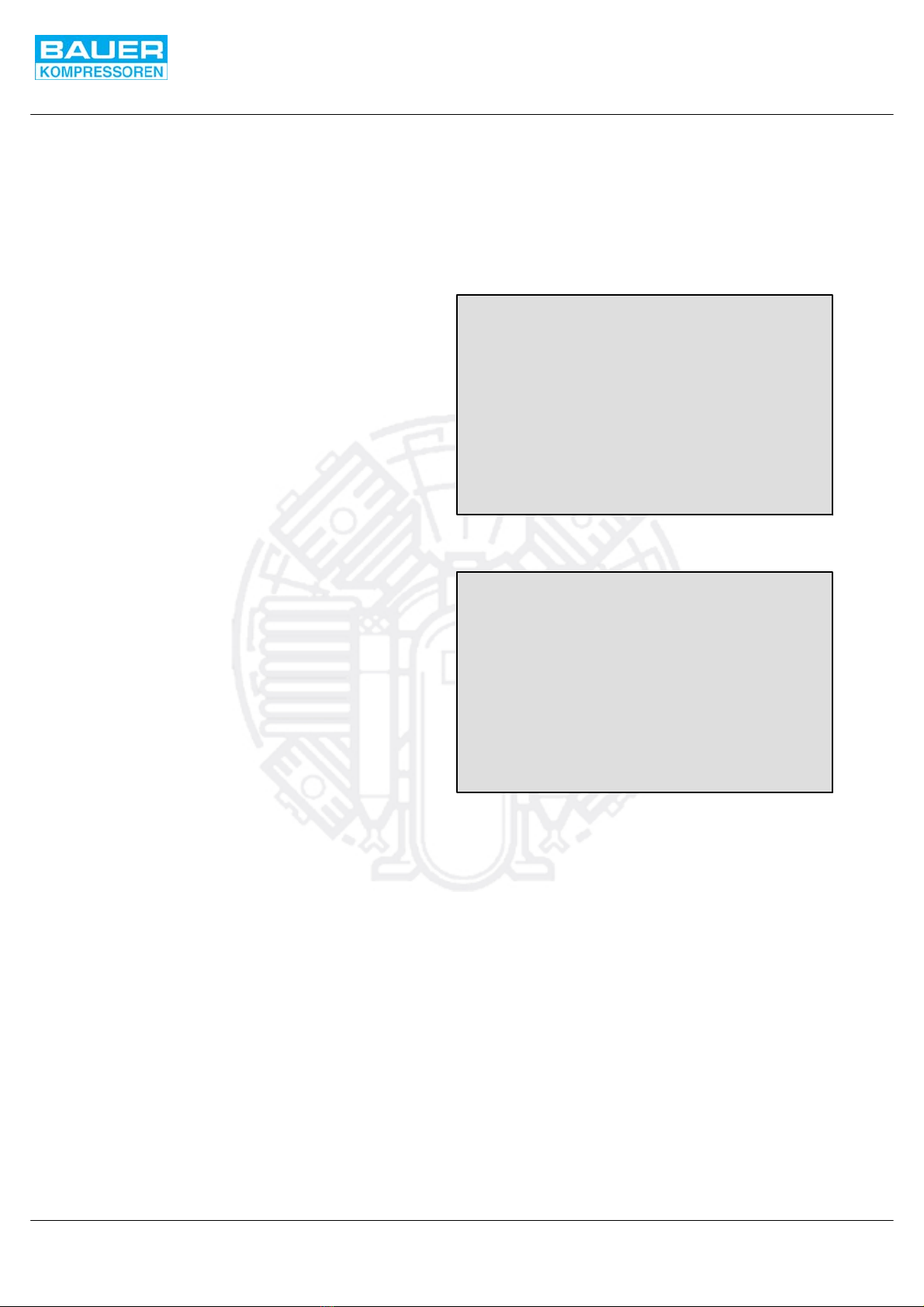
Fig. 10 Operation menue
***** OPERATION *****
Operation modes
Filter parameters
Cond.valve parameters
Pressure units
Language selection
Fig. 11 Operation modes
* OPERATION MODES *
Automatic >time
test sequence no
manual change no
Instruction Manual SECCANT IV
10
main menu. A new entry may be tried now. The number of
attempts is not limited.
With higher priority (level) codes you will automatically get
access to all lower priority levels, also, e.g. with the code for the
configuration level you will have access to all levels, whereas
with the operation code you would have access to the operation
level, only.
After entry of the correct access code the diplay changes to the
selected menu level.
OPERATION LEVEL
Entering the operation level, a survey menu will be opened at
first (Fig. 10).
The desired parameter can be selected with the and
keys. By pressing the enter key the selected adjustment page
will be shown. As an alternative, after having selected a menu
point, you may browse through the rest of the pages with the
menu key.
Operation mode
On the Operation modes page (Fig. 11) you can select between
diffferent operation modes:
Time operation mode
Test sequence
Manual change
Time operation mode
When the operation mode is set to time, the filter change−over
is controlled by the filter parameters setting for
filter/regeneration time, see Fig. 12.
Test sequence
When set to yes, a complete test cycle of the regeneration
dryer will be started, inclunding automatic condensate drain, for
test purposes.
Manual change
When set to yes, filters will be changed over from filtering to
regeneration and vice versa.

Fig. 12 Filter parameters
**** PARAMETERS ****
filter / regeneration
intervall 15 min
balance 40 sec
Fig. 13 Condensate drain valve parameters
* PARAMETERS *
* LANGUAGESELECTION *
German (D)
English (GB)
French (F)
Spanish (E)
Italian (I)
Swedish (S)
Dutch (NL)
**** PRESSURE UNITS ****
Megapascal (MPa)
Bar relativ (bar)
Pounds per sq. in. (psi)
Psi relativ (psig)
Cond.valve num. 1:
normal open
Intervall 15 min
Blowtime 6 sec
Fig. 14 Pressure units
Fig. 15 Language selection
Instruction Manual SECCANT IV
11
Filter parameters
Fiter regeneration
This parameter sets the time periods for filter change−over, and
pressure balance. The factory setting is 15 minutes and 40
seconds.
Condensate drain valve parameters
Pushing the menu key again will lead you to the adjustment of
the 1st condensate drain valve.
Consecutive pressing then leads to the adjustment of the other
condensate drain valves, if provided.
Pressure units
Pushing the menu key again or by directly selecting in the
operation menu will lead you to the pressure units page.
With the and keys and the enter key you can select
between the different pressure units.
If you are still using bar or psi units please
note that MPa is the only internationally valid
pressure unit !
Language selection
Pushing the menu key again or by directly selecting in the
operation menu will lead you to the language selection page.
With the and keys and the enter key you can select
between the different languages.

Fig. 16 Maintenance data page
**** MAINTENANCE ****
Main service ok
Dryer cartridge ok
Act. carbon cart. ok
Filter housing ok
Final separator ok
Logbook 20 R
[2368 h]
Fig. 17 Main service data page
* MAINTENANCE-INTVL.*
Main service
Actual runtime:
2345 h
Target runtime
4000 h
Reset > no
Fig. 18 Dryer cartridge service data page
* MAINTENANCE-INTVL.*
Dryer cartridge
Actual runtime:
812 h
Target runtime
1000 h
Reset > no
Fig. 19 Activated carbon cartridge data page
* MAINTENANCE-INTVL.*
Act. carbon cartr.
Actual runtime:
812 h
Target runtime
1000 h
Reset > no
Instruction Manual SECCANT IV
12
MAINTENANCE LEVEL
The maintenance level is accessible after prompting the correct
access code. At first you will come upon the maintenance data
window:
The difference now is that there will be a cursor which enables
you to jump to additional pages.
For the maintenance data of the first five criteria a similiar
window will appear where you can see the expired operating
time since the last service, and also the allowed interval time in
between two services. As soon as the actual time period
reaches 90 % of the max. allowed time, the status indication
changes from”ok” to “warn” to point out that a service will be due
in forseeable time.
If still no service should be accomplished, indication would then
change to “crit”, when the unit reaches 100% of the allowed
operationg hours.
Always keep an eye on the maintenance interval display and
service your unit in time! This will not only extend the lifetime of
your BAUER unit significantly, but also save you expensive
repairs at the most unfavourable point of time.
When the necessary service has been done, then quit the reset
by selecting “yes” on the lower right hand side of the display by
pressing the or key and confirm with the enter key. This
step is not reversible!
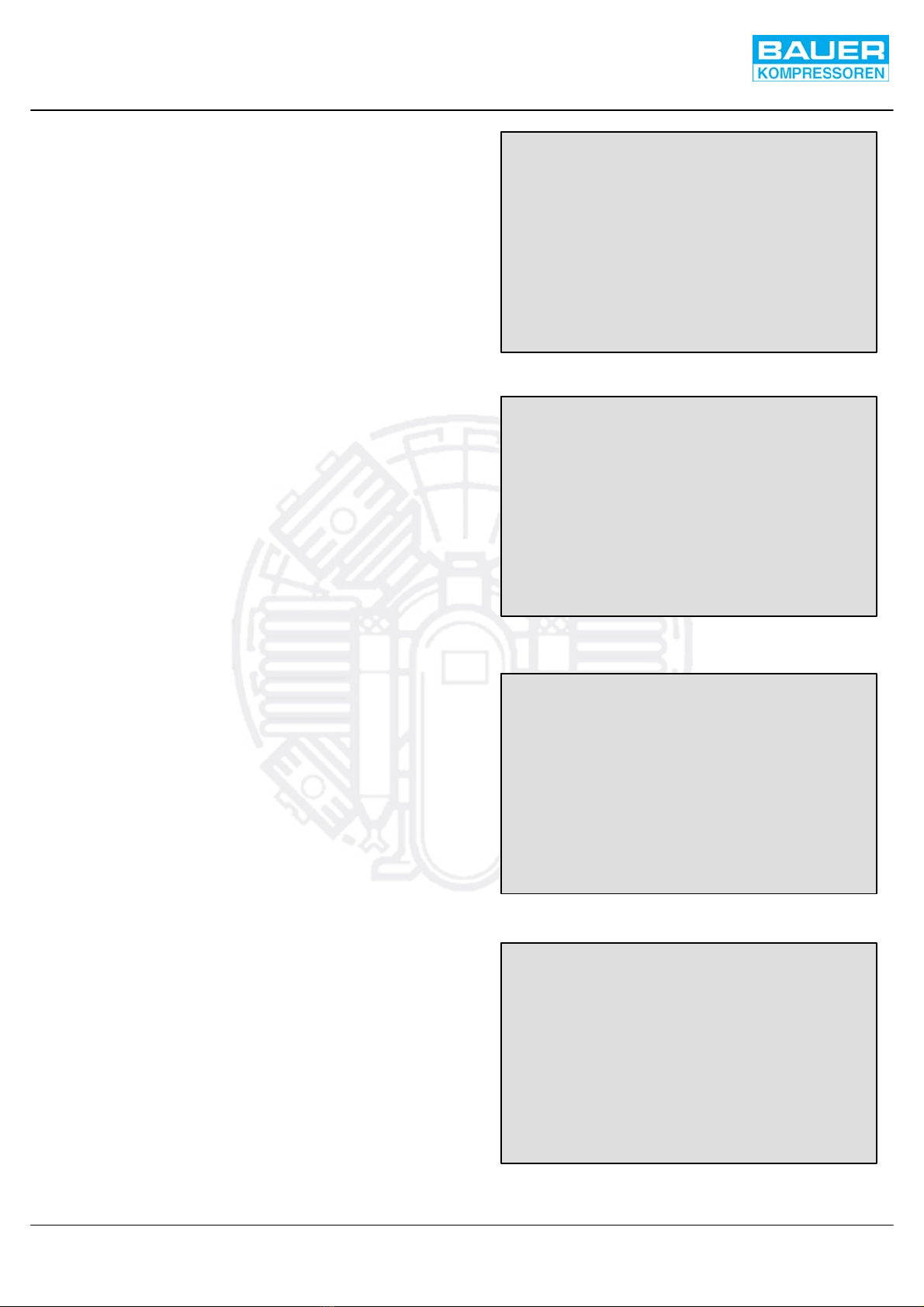
Fig. 20 Filter housing service data page
* MAINTENANCE-INTVL.*
Filter housing
Actual runtime:
784 x10 Cycl
Target runtime
2000 x10 Cycl
Reset > no
Fig. 21 Final separator service data page
* MAINTENANCE-INTVL.*
Final separator
Actual runtime:
2437 x10 cycles
Target runtime
8500 x10 cycles
Reset > no
Fig. 22 Logbook page
****** LOGBOOK ******
Display
Print
Fig. 23 Logbook page
****** LOGBOOK ******
Number: 1
Oper.h.: 12
Oper.min.: 24
Operhour 10
- - - - Oper. message:- - - - -
Securus saturated
check filter
Instruction Manual SECCANT IV
13
By consecutively pressing the menu key, you can browse
through the different maintenance pages.
Direct selection from the maintenance menu is also possible.
Finally you will get to the logbook page:
Logbook page:
After selection of the menu point “Display” a second window will
be opened showing the entries in the logbook. An example is
shown in Fig. 23., provided there are entries at all.
The latest (newest) message is shown as entry no. 1. If this is
an error message, it will be shown in bold letters and with two
digits, if it is an operation message, it will be in one line with the
respective headline.
Using the −und −buttons, the different entries can be
selected.
The print function is not activated for customer’s use. It allows
the logbook to be printed at BAUER service dept. with a special
service printer.
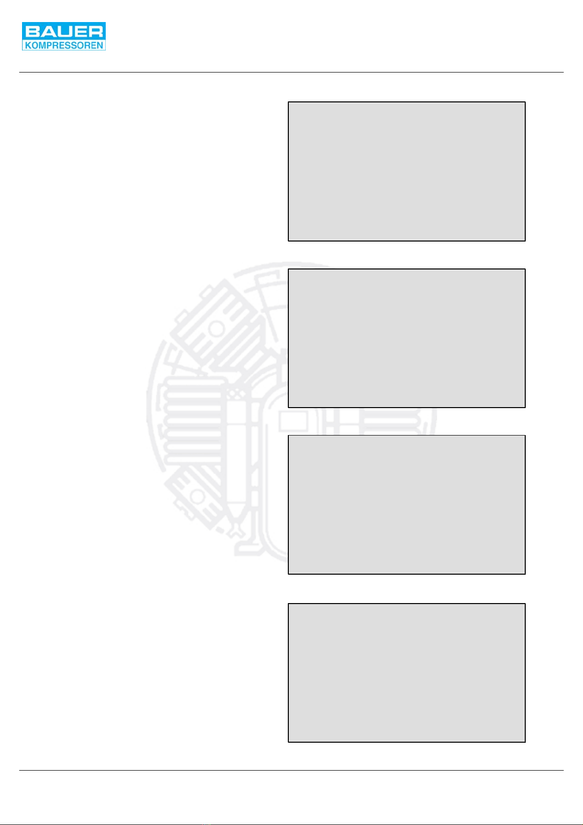
Fig. 24 Configuration page
*** CONFIGURATION ***
Sensor setting . . . . . . #
Sensor limits . . . . . . .#
Filter for logbook . . . . #
Fig. 25 Sensor setting page
*** SENSOR SETTING ***
Sens.press.res.
Raw value -1 bar
* factor 1000 %
+ offset 0 bar
= act. value -1 bar
Fig. 26 Sensor limits page
*** SENSOR LIMITS ***
Sens.cont.press
Shut-off >> 370 bar
Warning > --- bar
- - - - - - - - - - - - - - - - - -
Warning < --- bar
Shut-off << -15 bar
Fig. 27 Filter for logbook
FILTER FOR LOGBOOK
Msg. Number:
Unit running
Enable? no
Instruction Manual SECCANT IV
14
CONFIGURATION LEVEL
The configuration level allows basic adjustments to be
changed. Because of the possibility to change also values
concerning the warning and safety adjustments, this level is
accessible only with a special code.
The following menu pages can then be selected.
Sensor setting
The sensor calibration is performed in the same way for all six
possible sensors. Under “actual value” the present,
uncorrected raw value is displayed. With “offset” the sensor
characteristic can be shifted up or down, with “factor” the slope
of the characteristic can be changed. With all BAUER sensors,
this should be necessary in very special applications, only.
For both adjustments a reference instrument to measure the
actual value is necessary. By changing the “offset” and “factor”
values with the or keys you can adapt the calculated
characteristics to your specific requirements. The resulting,
corrected actual value will be displayed in the 4th line. Only this
value will be shown in all the other windows.
Sensor limits
The sensor limits adjustment is performed in the same way for
all six possible sensors.
Four values can be adjusted for each sensor.
The following table shows which values are actually processed
for each sensor. Adjustment is performed as usual by selecting
the value which you want to change with the and keys
and increasing or decreasing the values with the and
keys. After all values have been changed as desired, press the
enter key to accept and store the new values. Now this new
values are active throughout the program.
Please note that the limit values can only be adjusted in “bar”
regardless of the pressure units you have selected for being
displayed.
Filter for logbook
The filter for the logbook is defined as follows: with the −and
−keys the respective message is selected. Pressing the
−or −keys sets the message or error to be recorded or not.
On “Enable?” “yes” the message will be recorded. On “no” it will
not be recorded.
This manual suits for next models
1
Table of contents
Popular Dryer manuals by other brands


Miele
Miele Novotronic T 1520 operating manual

Frigidaire
Frigidaire FER641FS - 27" Electric Dryer owner's guide

Menuett
Menuett 001-641 operating instructions

AEG
AEG Lavatherm 720 operating instructions

Fisher & Paykel
Fisher & Paykel DE09 Use and installation guide

Bobrick
Bobrick B-700 installation instructions


