bauhaus 20734370 User manual
3 Drawer Workbench
ITEM #20734370
1

2
CONTENTS
Safety
Package Contents
Precautions
Assembly Instructions
Care And Maintenance
3
4
5
6-14
14
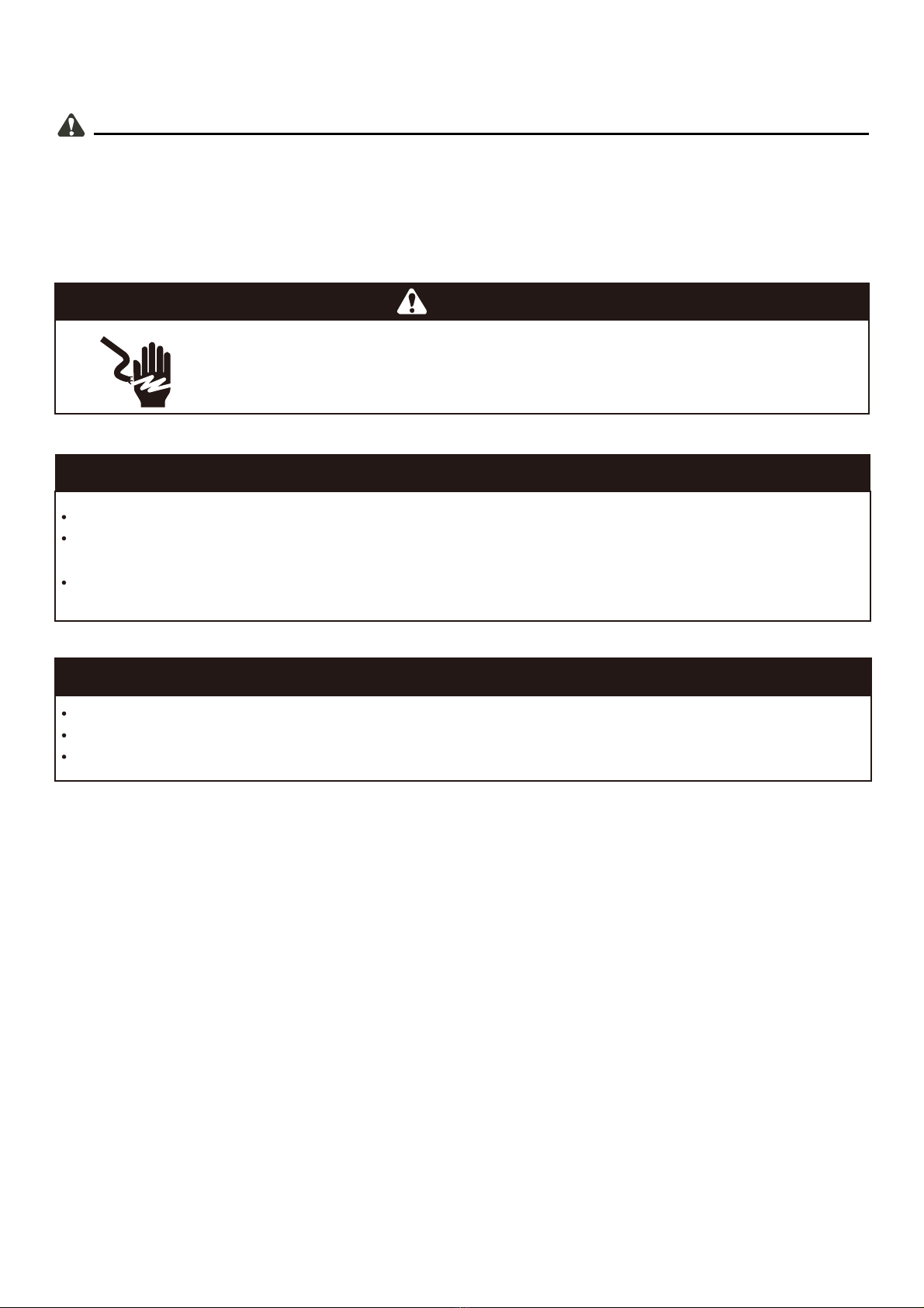
Safety
3
Please read and understand this entire manual before attempting to assemble, operate or install the
product.
CAUTION
DO NOT mount this product on a truck bed or any other moving object.
DO NOT alter this product in any manner.
The maximum weight for each drawer should NOT exceed 100 pounds.
WARNING
ELECTRICAL SHOCK HAZARD. Do not plug the cord into an outlet with wet
hands. Do not use this tool chest near a bathtub, shower or swimming pool.
Follow this manual for recommended usage.
DANGER
KEEP CHILDREN AWAY from item at all times.
DO NOT stand on this product. You may fall which could cause personal injury and
product damage.
BE CAREFUL when opening more than one drawer.

4
AA
BB
PACKAGE CONTENTS
34
CC
34
35
36
37
1
2
3
4
5
6
7
8
9
10
11
12
13
14
15
16
17
18
19
20
21
No. Description
Quantity
No. Description
Quantity
1
1
1
2
1
1
1
1
1
2
2
1
1
1
3
3
2
2
2
1
1
Rear leg (left)
Front leg (left)
Side panel (left)
Side frames (left & right)
Rear leg (right)
Front leg (right)
Side panel (right)
Drawer slide panel (left)
Drawer slide panel (right)
Slide support (intermediate)
Bottom frame (front & rear)
Base panel
Upper panel
Back panel
Drawer side panel (left)
Drawer side panel (right)
Drawer bottom panel (small)
Drawer front (small)
Drawer back (small)
Drawer bottom panel (large)
Drawer back (large)
Drawer front (large)
Storage cage side panel (left)
Hinge (left)
Hinge (right)
Storage cage lid
Storage cage side panel (right)
Storage cage bottom panel
Pegboard
Light support bracket
Light
Light power cord
Wooden table top
Hanging hook
Hook for screwdriver
Short hook
Hook for pliers
Long hook
M6x10 mm Screws
M6x8 mm Screws
M4x8 mm Screws
1
1
1
1
1
1
1
1
1
1
1
1
5
3
4
1
1
50
74
2
22
23
24
24
25
26
27
28
29
30
31
32
33
34
35
36
37
AA
BB
CC

PREPARATION
5
AA BB
PRECAUTIONS
Before you begin the assembly of this product, ensure that all parts are present. Compare all parts
with the package contents list and hardware contents list above. If any part is missing or damaged,
do not attempt to assemble the product.
Estimated Assembly Time: 90 minutes
Tools Required for Assembly (not included): Phillips Screwdriver
M4x6 mm
Screws
Qty.50
M6x10 mm
Screws
Qty.74
M4x8 mm
Screws
Qty.2
CC

6
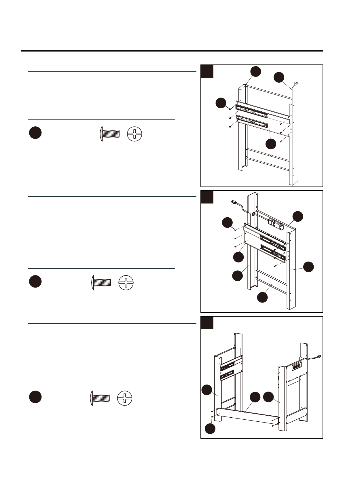
ASSEMBLY INSTRUCTIONS
1
AA
Hardware Used
Hardware Used
M6x10 mm x4
Step 1
Step 2
Use 4 screws M6x10 mm to as shown the front left (2L)
and the rear left (1L) leg to the floor frame (4L) fixed to
make. Make sure that the Edge of the base frame
pointing upwards.
1
2
4
AA
AA
1
3
2
2
AA
M6x10 mm x4
Attach the left side plate (3) with 4 M6x10 mm screws.
Make sure that the holes of the bent edge are up.
Note: Do not overtighten or you may damage it possibly the screws.
7
ASSEMBLY INSTRUCTIONS
3
4
5
AA
M6x10 mm x6
AA
M6x10 mm x14
AA
M6x10 mm x4
Step 3
Step 4
Step 5
1
8
9
4
7
5
6
6
11
2
2
Align the left drawer slide panel (8L) with the predrilled
holes, ensuring the slides are toward the front
of the unit. Attach using screws (AA).
Repeat steps 1-3 on the right side with the parts 4,5,6,7
and 9 Then you run the power cable (27) of the
connector (36) through the predrilled hole in the right
rear leg (5R).
AA
AA
AA
Screw the parts (11) with the left and right by 8
M6x10 mm screws use and make sure that the edges
with show the hole to the top
Hardware Used
Hardware Used
Hardware Used

8
6
7
8
AA
M6x10 mm x12
AA
M6x10 mm x4
Setp 6
Attach a bottom frame(11) to the front of the left and
right rear legs(1L and 5R) using screws(AA). Ensure
the holes on the bottom frame(11) are facing up.
5
1
11
11
12
AA
4
5
14 1
AA
AA
Setp 7
Place the base plate (12) onto the bottom frame
and secure it with M6x10 mm screws 12 fixed.
Setp 8
Attach the rear side portion (14) with 4 M6x10 mm
screws.
AA
M6x10 mm x4
ASSEMBLY INSTRUCTIONS
Hardware Used
Hardware Used
Hardware Used

9
9
10
11
Setp 9
Insert four M6x10 mm screws into the foreseen holes of
the rear side member (14) and push it down. These
screws attach the now middle drawer (10).
AA
M6x10 mm x4
AA
M6x10 mm x4
AA
M6x10 mm x2
AA
2
6
13
13
10
AA
Setp 10
Attach the front side member (13) with 4 M6x10 mm
screws. If more than two M6x10 mm Screws to the middle
drawer member (10) to the to attach the front side part.
Setp 11
Secure the intermediate slide support(10) to the upper
panel(13) by insertig screws(AA) through the slide
support(10) and into the upper panel(13).
ASSEMBLY INSTRUCTIONS
Hardware Used
Hardware Used
Hardware Used

10
AA
M6x10 mm x6
13
12
Step 13
Assembly of small drawers: First screw the drawer front
part (18) with the two drawers side parts (15) (16) by
means of 4 M4x6 mm screws. Then fasten the posterior
drawer base with 4 M4x6 mm screws.
Attach the base plate with 4 M4x6 mm Screws. Repeat
this process to the other drawer assemble.
Setp 12
Insert the bamboo plate (32) on the worktop
and securing it with 6 M6x10 mm screws.
BB
15
18 16
19
BB
M4x6 mm x24
17
32
14
BB
M4x6 mm x7
22
21
16
15
BB
Step 14
Assembly of large drawers:the drawer side parts (15) (16)
with the front A drawer member (22) 4x6 mm screws
and 4 then attach the drawer rear wall (21) with 4 other
M4x6 mm screws on. Attach the tray bottom plate (20)
having 7 mm M4x6 Screws.
20
ASSEMBLY INSTRUCTIONS
Hardware Used
Hardware Used
Hardware Used

11
15
Setp 15
Pull the rails for the drawers all the way out,
place the drawers and slide it slowly back again.
16
16
Step 16
Insert the bottom portion of the storage compartment (31)
above the holes and press it down until it clicks into place.
Then they put the left side panel of the Storage
compartment and press it well down to it clicks into place
and take it with M6x10 mm screw can attach.
Attach the side panel (23) with three M4x6 screws and
repeat the process on the other side.
Now screw the gas cylinder left and right (24R and 24L)
attached to the screws.
23
23
24
AA
AA
24
26
31
31
28
25
26
28
AA
M6x10 mm x6
ASSEMBLY INSTRUCTIONS
Hardware Used

12
17
AA
Step 17
Attach the back wall (28) with 4 M6x10 mm screws.
28
15
AA
M6x10 mm x4
18
19
29 29
30
CC
M4x8 mm x2
Step 18
Bring the light holder (29) with 2 M4x6 mm screws on
the underside of the stacking compartment.
Step 19
Plug the cable for the light in the light and pass the
cable through the hole.
30
27
ASSEMBLY INSTRUCTIONS
Hardware Used
Hardware Used

13
20
33
21
Step 20
Place the S-shaped hanging hooks on the right side wall.
Step 21
Hang the hanging hook for pliers, screwdriver, etc. to
any position on the rear wall.
ASSEMBLY INSTRUCTIONS
14
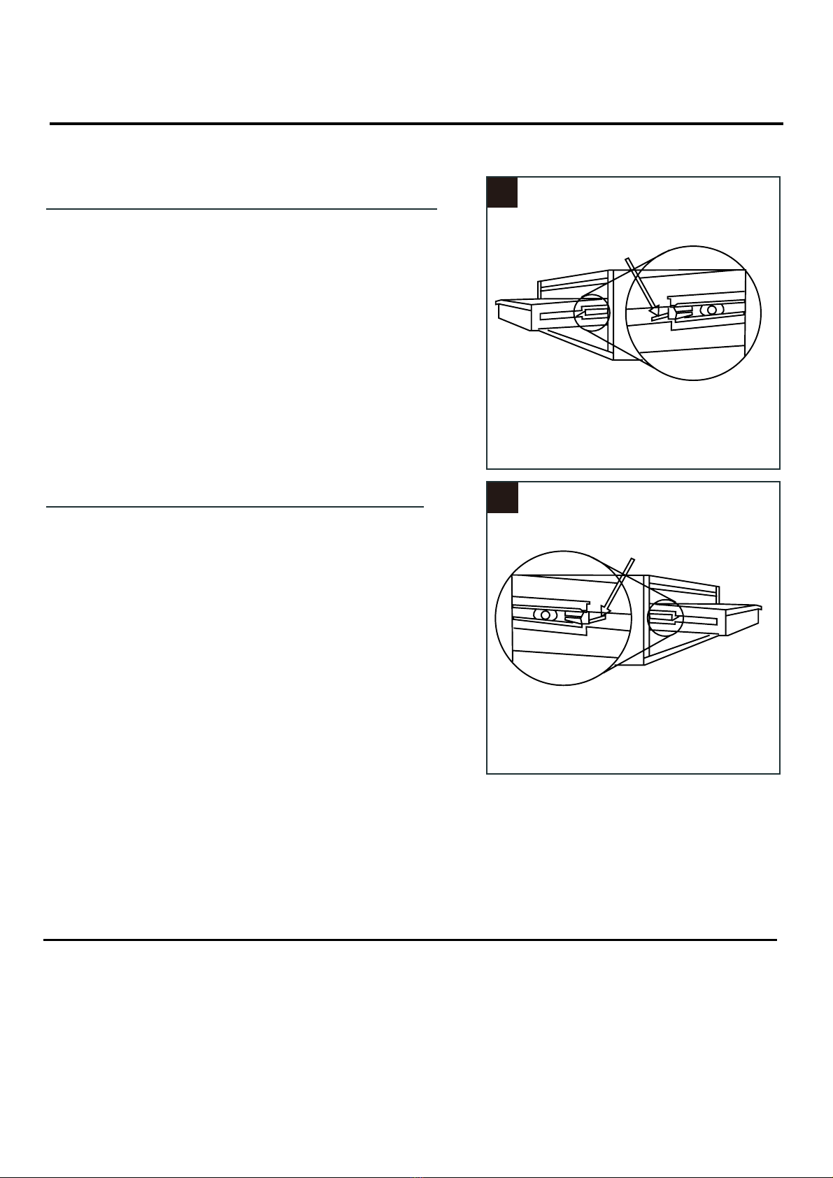
Drawer removal
Pull the drawer out completely.
1
2
Replace the drawer
Pull the rails as much as possible out.
Put the drawer back into the rails.
DRAWER REPLACEMENT
Extend the drawer slides from the tool chest.
Insert the rail on each side of the drawer into the slots in the drawer slides, being careful that the drawer
rail and slide stay aligned while retracting slide! Do not force them!
Once inserted, completely close the drawer to set the slides in their regular operating positions.
Step 2
Pull the release lever on the left page. Now take
the drawer out rail.
ASSEMBLY INSTRUCTIONS
Step 1
Press the release lever on the right side.
Care and Maintenance
Powder coated surfaces should be suitable with a lint-free cloth and a means to be cleaned.
Liquids should be quickly wiped and dried.
If you cover her workbench with a tarpaulin or similar while you are not using it remains clean.
Table of contents
Popular Tools Storage manuals by other brands


Husky
Husky H9CH3 Use and care guide

Omni cubed
Omni cubed SLIM SLAB TABLE HD user guide

Husky
Husky 410-027-0111 Use and care guide

PROformance Hoops
PROformance Hoops PKT3609D Operator's manual

Black & Decker
Black & Decker WorkMate 125 instruction manual

Grobet USA
Grobet USA New Jewelry Work Bench 13.071 Assembly instructions


