Beale Street Audio BPS-65 User manual

Beale Street Audio
BPS-65 and BPS-80 Active In-Room Subwoofers
Installation Guide

2
Introduction
Congratulations and thank you for purchasing the Beale Street Audio BPS-
65 or BPS-80 Active In-Room Subwoofer!
The BPS Active In-Room Subwoofers may be small in physical appearance,
but it has all the muscle you need to get the house thumping levels.
The BPS Active In-Room Subwoofers feature a LFE (Low Frequency Effects)
input, stereo/mono line level audio input that can receive full band audio
from any audio amplifier, and also stereo speaker level input. Amplified
stereo audio will pass through unprocessed to a pair of connected stereo
speakers using the speaker high level outs. The signal from the speaker
level input will also be processed by the crossover and volume controls to
enhance and optimize low frequency content.
The adjustable crossover allows fine-tuning to properly complement any
full-range, or limited range, speakers.
Please read and follow the instructions in this User Guide to assure you
are getting the most from your new Beale Street Audio active in-room
subwoofer!

3
Features
6.5” Active In-Room Subwoofer
BPS-65
• Engineered black matte wood cabinet
• Black cloth magnetic grill
• 200W built-in amplifier
• Kevlar woofer with butyl rubber surround
• Stereo or mono audio line level input (RCA)
• Stereo speaker level input and pass through
• Adjustable subwoofer crossover frequency
• Adjustable phase (0° or 180°)
• 110/220V
8” Active In-Room Subwoofer
BPS-80
• Engineered black matte wood cabinet
• Black cloth magnetic grill
• 200W built-in amplifier
• Kevlar woofer with butyl rubber surround
• Stereo or mono audio line level input (RCA)
• Stereo speaker level input and pass through
• Adjustable subwoofer crossover frequency
• Adjustable phase (0° or 180°)
• 110/220V
What’s Inside?
• BPS-65 Subwoofer
• Black cloth grill
• AC Power Cord
• Product Manual
• BPS-80 Subwoofer
• Black cloth grill
• AC Power Cord
• Product Manual
BPS-65 BPS-80
4
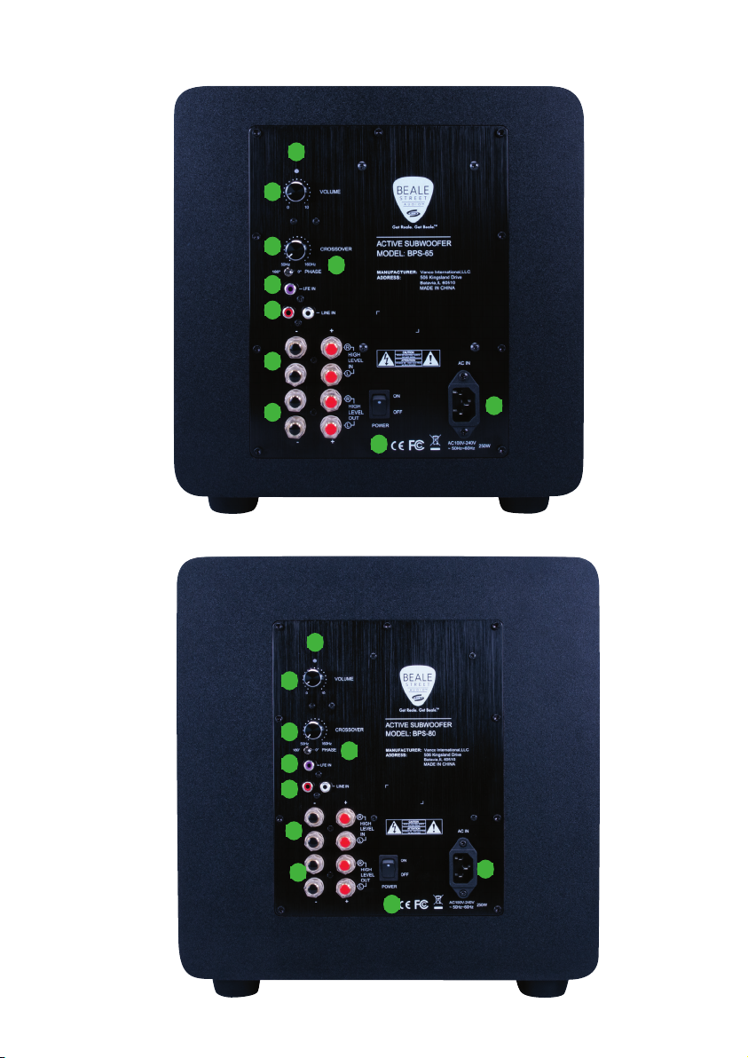
Rear Panels
BPS-65
BPS-80
1
2
3
4
5
6
7
8
9
10
1
2
3
4
5
6
7
8
9
10

5
1. RCA INPUT - Two, RCA jacks. Stereo or mono line level audio input
2. LFE (Low Frequency Effects) INPUT- Single RCA jack
3. HIGH LEVEL IN- Connect to the speaker level OUT on an audio amplifier passthrough
full-band audio to the Speaker Level OUT
4. HIGH LEVEL OUT- Connect to speakers appropriately rated for the amplifier connected
to Speaker Level IN. Passthrough full range speaker-level audio from an amplifier
connected to the Speaker Level IN
5. VOLUME- Adjusts the audio output level to the connected subwoofer. Set to an
appropriate level for a smooth, natural sounding transition to extend and enhance the
low frequency output of the full- range speakers connected to Speaker Level OUT
6. CROSSOVER- The Crossover sets the frequency at which audio content will pass.
RANGE: 40Hz to 160Hz
7. PHASE - The Phase setting allows compensation for subwoofer location relative to
the main speakers. Adjust the Phase setting to the point of highest sub audio output.
RANGE: 0º or 180º.
8. POWER SWITCH- turn the amp/sub in on and off
9. LED POWER LIGHT
10. AC MAINS - One, two-prong socket. Use the supplied 2-pin power cable to connect the
unit to an external AC power supply. AC 100V-240V, 50Hz-60Hz
Installation
Your Beale Street Audio subwoofer has been designed to operate at frequencies generally
below 150 Hz. Because low-frequency information in this range essentially is non-
directional, your subwoofer can be placed virtually anywhere in the room.
There are, however, some general rules that you should follow when locating your
subwoofer: For maximum output the subwoofer should be against a wall or in a corner.
Placing the sub in a corner will increase its output but may result in lower bass quality. If
placing in a corner it is recommended that you test the location prior to final installation.
While a single Beale Street Audio subwoofer will always sound great, the use of two
subwoofers will enhance your system’s performance by providing a smoother and more
consistent low frequency response. In this application it is recommended that you place
one subwoofer on the front wall and the second subwoofer on the side wall about 1/3 to
½ of the of the room’s length.

6
Connections
All connections are conveniently placed on the rear panel for sane wire
management, convenient connections and simple service.
NOTE: Do not connect the AC power cord or turn the amp on until all
connections have been made and confirmed. Making connections with the
power on can result in...well... undesirable circumstances...that may not be
covered under the factory warranty.
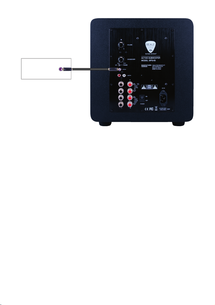
RCA Input and LFE Input
Receiver/Processor
Pre Out
7
• Using a stereo or mono RCA-RCA cable with gold ends, connect the LFE
OUT, Sub OUT, or other line level audio OUT on an amplifier, surround
receiver or other audio preamp to either the LFE or LINE in on the BPS
subwoofer.
Receiver/Processor
LFE/Sub Out
AC Mains
• After all connections have been made connect the supplied AC Power
Cord to an unswitched AC power outlet.
8
• In this configuration, speaker level audio input will passthrough at full
bandwidth to the Speaker Level OUT.
• NOTE: Do not connect the AC power cord or turn the amp on until all
connections have been made and confirmed. Making connections with
the power on can result in...well...undesirable circumstances...that may
not be covered under the factory warranty.
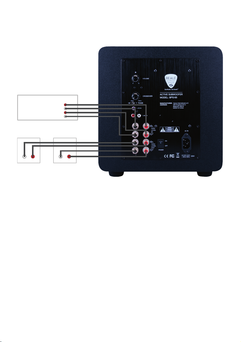
Speaker Level Input Configuration
Receiver/Processor
Speaker Out
R
L
Right Speaker Left Speaker
_+_+
_
+
_
+

9
Speaker Level In
1. Use 16AWG 2-conductor stranded speaker wire for speaker
connections
2. Strip approximately 1/2 to 3/4 of an inch off the ends and twist the
strands together so there are no loose strands that can cause shorts
3. While observing proper wire polarity, connect the Speaker Level OUT of
the Audio Amp/ Receiver to the appropriate Speaker Level IN + and -
terminals. Be sure there are no loose strands that can cause shorts
4. Confirm connection and polarity
Speaker Level Out
1. Use 16AWG (min) 2-conductor stranded speaker wire for speaker
connections
2. Strip approximately 1/2 to 3/4 of an inch off the ends and twist the
strands together so there are no loose strands that can cause shorts
3. While observing proper wire polarity, connect the Speaker Level OUT to
the appropriate left and right speaker + and - terminals. Be sure there
are no loose strands that can cause shorts.
4. Confirm connection and polarity

10
Description BPS-65 BPS-80
Maximum Output Power 220W
THD <1%
Frequency Response 38Hz-300kHz 28Hz-300kHz
Signal to Noise 71dB
Crossover 40Hz-160Hz
Phase 0°,180°
Line Voltage 110-120V/220-240V
Max Power Consumption 250W
Dimensions 11.65” L x 11.65” W x 12.4” H 13.5” L x 13.5” W x 14.25”H
Weight 12.04 lbs 15.56 lbs
Specifications

11
Limited Warranty
With the exceptions noted in the next paragraph, Vanco warrants to the original purchaser
that the equipment it manufactures or sells will be free from defects in materials and
workmanship for a period of two years from the date of purchase. Should this product, in
Vanco’s opinion, prove defective within this warranty period, Vanco, at its option, will repair
or replace this product without charge. Any defective parts replaced become the property
of Vanco. This warranty does not apply to those products which have been damaged due to
accident, unauthorized alterations, improper repair, modifications, inadequate maintenance
and care, or use in any manner for which the product was not originally intended.
Items integrated into Vanco products that are made by other manufacturers, notably
computer hard drives and liquid crystal display panels, are limited to the term of the
warranty offered by the respective manufacturers. Such specific warranties are available
upon request to Vanco. A surge protector, power conditioner unit, or an uninterruptible
power supply must be installed in the electrical circuit to protect against power surges.
If repairs are needed during the warranty period, the purchaser will be required to provide
a sales receipt/sales invoice or other acceptable proof of purchase to the seller of this
equipment. The seller will then contact Vanco regarding warranty repair or replacement.
TECHNICAL SUPPORT
In case of problems, please contact Vanco Technical Support by dialing 1-800-626-6445.
please have the Model Number, Serial Number (affixed to the bottom of the unit) and
Invoice available for reference during the call. Please read this Instruction Manual prior to
calling or installing this unit, since it will familiarize you with the capabilities of this product
and its proper installation. All active electronic products are 100% inspected and tested
to insure highest product quality and trouble-free installation and operation. The testing
process utilizes the types of high-definition sources and displays typically installed for
entertainment and home theatre applications. For additional information please visit www.
vanco1.com.
LIABILITY STATEMENT
Every effort has been made to ensure that this product is free of defects. The manufacturer
of this product cannot be held liable for the use of this hardware or any direct or indirect
consequential damages arising from its use. It is the responsibility of the user and installer
of the hardware to check that it is suitable for their requirements and that it is installed
correctly. All rights are reserved. No parts of this manual may be reproduced or transmitted
by any form or means electronic or mechanical, including photocopying, recording or by
any information storage or retrieval system without the written consent of the publisher.
Manufacturer reserves the right to revise any of its hardware and software following its
policy to modify and/or improve its products where necessary or desirable. This statement
does not affect the legal rights of the user in any way.

A BRAND FROM
Vanco International, LLC
506 Kingsland Drive
Batavia, IL 60510
Phone: 800.626.6445 Fax: 630.879.9189
www.getbeale.com
www.vanco1.com
©2020
The Vanco logo, Sonic Vortex logo, and Beale Street Audio Inc. logo are registered trademarks of
Vanco International, LLC.
Vanco, Sonic Vortex, Beale Street Audio, Get Reale. Get Beale., the Vortex logo, and the Beale Street
Audio logo are trademarks of Vanco International, LLC.
This manual suits for next models
1
Table of contents
Other Beale Street Audio Subwoofer manuals


