Beezar Audio ecp audio T4 User manual

T4headphone amplier
Owner’s Manual
beezar audio
ecp audio

This page intentionally left blank.

Published by Beezar Audio
March 2019
Copyright 2019, Beezar, L.L.C.
All Rights Reserved
http://www.ecpaudio.com
http://www.beezar.com
http://www.beezaraudio.com
3

Voltages exceed 300V inside the amplier.
Never open the case or remove the lid (for
changing tubes) without turning the ampli-
er o and unplugging the wall power. Never
operate the amplier with the case lid o
or not rmly screwed into place. Except for
changing tubes, there are no user serviceable
parts inside. Always ensure that the ampli-
er is plugged into a grounded outlet with a
properly grounded power cord.
Do not allow foreign objects or any liquid to
fall into the cooling slots or the tube holes. If
a foreign object or liquid falls into the ampli-
er, immediately switch o the power and
disconnect the amplier from the wall outlet.
Do not touch the unit until it is completely
disconnected. If you are unable to clear the
object by removing the amplier top, return
the unit to Beezar Audio for servicing.
Caution Warning - High Voltage!
SAFETY
Foreign Objects
Vacuum Tubes and Heat
Do not touch the tubes while the amplier is
operating. The tubes can attain temperatures
higher than boiling water. If changing tubes,
allow sucient time for the tubes to cool.
Do not leave the amplier unattended while
turned on or turned on for extended periods.
4

Do not connect the
amplier to any power
source other than the
type and voltage as
specied on the rear of
the amplier.
Power Sources
If the unit is left unused for an extended period, disconnect the ampli-
er from the wall outlet.
Non-Use
The amplier is set up
as either 110VAC or
220VAC, NOT BOTH.
Connecting to an
improper outlet at the
wrong voltage may
severely damage or
destroy the amplier.
5

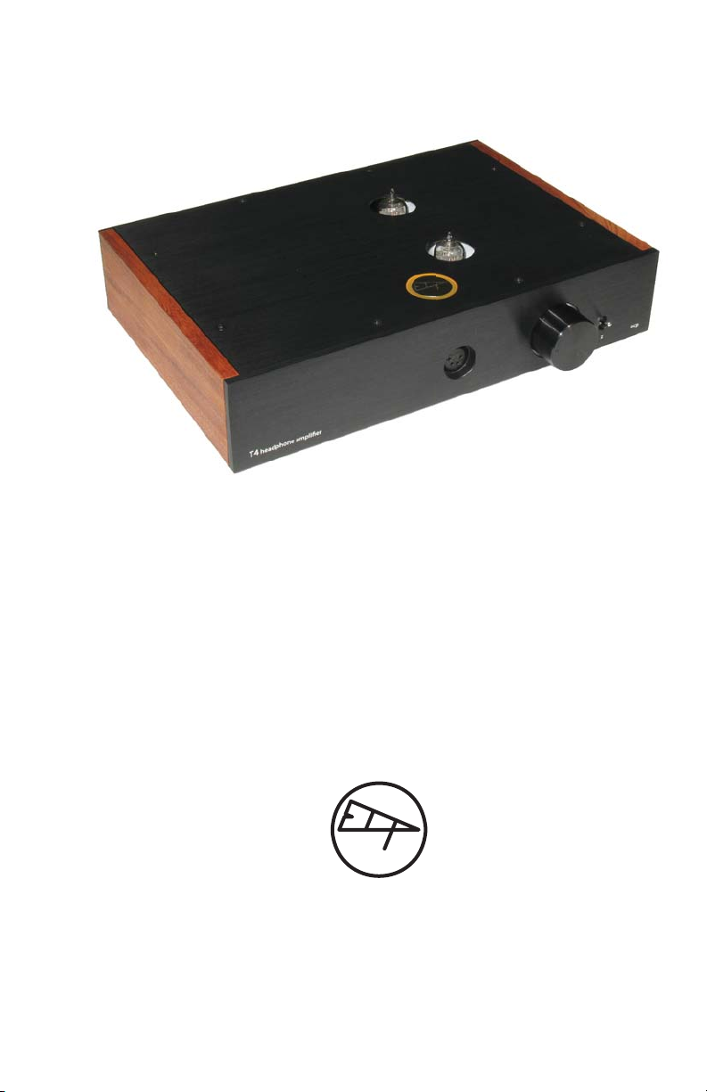
The T4 dierential hybrid parafeed headphone amplier, custom as-
sembled by Beezar Audio, was created by ECP Audio. The T4 continues
in the tradition of its predecessor, the ECP Audio/Beezar Torpedo III. Its
circuit and conguration are totally unique in the world of headphone
audio. The T4 combines tubes with a fully dierential solid-state out-
put, feeding into custom-manufactured Lundahl output transformers
for the nest in single-ended, zero-feedback output from a headphone
amplier. The result is perhaps the nest tube headphone amplier
available anywhere at this price point.
Amplier Design Description
INTRODUCTION
The tubes are congured in a long-tail pair that results in a fully dier-
ential output. From there, a fully dierential solid-state buer is used,
terminating in output transformers congured into a parafeed ar-
rangement, where the dierential signal is combined back into a single
ended connection at the headphone jack. Because of the fully dier-
ential circuit, common mode distortion is fully cancelled out. At the
same time, the solid-state buer output after the tubes results in more
power than would be available from the tubes themselves. The output
transformers assist with this, ensuring that ample current and voltage
are available, regardless of the impedance of the load.
ECP Audio designed the T4 headphone amplier to utilize the ubiq-
uitous 12A*7 audio tube family. Specically, the T4 is designed for the
12AY7 or 12AT7 tube, but others can be used that meet the general
12A[T, U, V, X, Y, Z]7 tube specications. There are many, many other
tube types that will work, too. Refer to the tube section of this manual
for a list.
The T4 includes a “Z”switch that allows switching between low and
high-impedance loads (75 to 300 ohms). This switch may be thrown at
any time - even while music is playing and headphones are plugged in.
Note also that with a true, output-transformer-coupled amp, there is
no need for any kind of power-on or power-o headphone protection.
6

• Custom machined and nished casework, laser-etched
• Hand-oiled, solid-hardwood sides
• ECP Audio custom-designed Lundahl output transformers
• ECP Audio custom-designed, toroid power transformer
• New thin-lm Vishay/Beyschlag resistors throughout
• Special Vishay low-noise nickel chrome tube plate resistors
• Genuine ALPS “Blue Velvet” volume control
• Large, custom-machined solid-aluminum volume knob
• Neutrik 4-pin XLR headphone jack, compatible with 4-pin XLR
balanced headphone connectors
• Advanced thermal bar heat rejection through the casework
Components List
Specications*
Measurement Item 300R 78R 61R
Frequency Response, 20-20kHz ±0.4dB ±0.4dB ±0.4dB
40-15kHz ±0.3dB ±0.3dB ±0.3dB
Noise Level, dB (A-weighted) -94.6 -94.5 -97.1
Dynamic Range, dB (A-weighted) 94.6 94.4 97.1
THD, % 0.014 0.089 0.169
IMD + Noise (A-weighted), % 0.009 0.051 0.096
Stereo Crosstalk, dB -79.7 -81.4 -83.1
Power, mW, 1kHz 290.4 314.1 239.0
Vpp 26.4 14.0 10.8
Vp 13.2 7.0 5.4
Vrms 9.3 4.9 3.8
I,ma 31.1 63.5 62.6
Power, mW, 500Hz 290.4 314.1 239.0
Power, mW, 100Hz 290.4 314.1 239.0
Note that performance measurements are only a guide to the basic capability of the
amplier. Actual measurements are almost entirely dependent on the tubes and
can vary widely, depending on the type and quality. These measurements were
taken with NOS (New Old Stock) Mullard CV4024 tubes using RMAA software and
an M-Audio Firewire Audiophile. Power measurements were estimated using static
resistor loads (value indicated) and an oscilliscope at the point just prior to visibly
distorting the output wave (clipping). 12AX7 tubes were used for the power mea-
surements to provide sucient gain for clipping.
*
7

11
1
111
2
211
3
3
11
1
1
11
2
2
11
3
3
4-pin XLR Headphone Jack (output)
Adapters to 1/4”TRS for standard headphones are available at Beezar Audio
NOTE: 4-pin XLR-equipped, balanced headphones may connect directly without an adapter
Volume control
Output impedance switch, Up for high-impedance headphones (300 ohms), Down for low-impedance
headphones (75 ohms or less). Note that output impedance in the low position is optimized for 75
ohms. Good for headphones down to 60 ohms, but power may be limited at 32 ohms and below.
Amplier Physical Description
Front Panel
8

11
2
211
3
311
4
4
11
5
5
11
6
611
7
7
11
1
1
11
1
1
11
2
2
11
3
3
T4 Headphone Amplier Serial Number
RCA Jacks (Input)
Cooling Slots - Do NOT Block
11
4
4Power Switch
11
5
5
11
6
6
11
7
7
Fuse Drawer
IEC Connector (for wall power)
Input Voltage Indication
Rear Panel
9

11
3
311
2
211
1
1
11
4
4
11
8
8
11
7
7
11
6
6
11
5
5
Top Panel
10

11
1
1
11
2
2
11
3
3
Z Switch
Volume Knob
ECP Logo
11
4
4Cooling Slots - Do NOT Block
11
5
5
11
6
6
11
7
7
IEC Connector, Fuse Drawer, & Power Switch
Tube Holes (2 total)
RCA Jacks
There are eight (8) undercut screws that must be removed to lift the lid in order to change tubes. Use a hook
under the tube holes or cooling slots to pop the lid up. (The lid is tightly t and will be wedged into place.)
Once popped up, use your hands to gently remove the lid. Further details can be found in the Tubes section.
WARNING! Do not over-tighten screws! With the countersinks, the holes are quite thin. Only a gentle tighten-
ing is needed (the lid is already wedged into place). Note that you may need to adjust the brackets into posi-
tion before replacing the lid.
11
8
8Phillips Head Screws (8 total)*
*
11

OPERATION
Installation/Break-In
Location/Ventilation
Ensure that the amplier is located on a solid footing. Provide suf-
cient room for the power cord and ensure that the cord has a secure,
grounded connection with the wall outlet. Tubes are unshielded
devices and we recommend that the amplier is located away from
interfering sources such as computers and cell phones. Do not place
the amplier on top of another heat-producing device.
The amplier is provided with cooling slots on the rear and on the top
of the amp, in addition to the tube holes themselves. Provide at least
12 inches of clear space above the amplier and at least 4 inches in the
rear for proper cooling. The amplier can become warm if operated for
more than a few hours, especially if some of the higher heater current
tubes are used (see Recommended Tube List). Turn the amplier o if
it’s not being used and do not allow the amplier to run unattended.
Tube Warmup
Generally speaking, the tubes are suciently warmed up in about a
minute after turning the power on. Contrary to many reports, great
listening can be achieved very quickly after powering on the amplier.
It may be true that best results are obtained after a few more minutes,
but Beezar Audio and ECP Audio do not necessarily subscribe to rec-
ommendations you may see for hours of operation before achieving
optimum performance.
Note that some tubes – particularly genuine NOS Mullard or Brimar
tubes, will “ash” upon initial turn on. They will then act like any other
tube and achieve a constant glow once the heaters are warmed up (30
sec. – 1 minute). This “ash” is completely normal for those tube types
and there is no cause for alarm. Note that newly manufactured tubes
with the Mullard brand are not the same and will not present this be-
havior (neither will almost any other tube).
Break-In
Other than the tube warmup mentioned above, no special treatment
is needed for amplier break-in. You may notice some subtle changes
in the rst hour or two, but we do not recommend the hours and hours
of burn-in that you may see discussed elsewhere.
12

Tubes
General Care
Vacuum tubes, or sometimes referred to as electron tubes, are manu-
factured of glass. They heat up and provide some light from the heat-
ed parts inside. That said, they are not entirely like old incandescent
light bulbs. The glass is much thicker than a light bulb, but they can
still break. They also get just as hot as an old incandescent light bulb.
A vacuum tube break will often occur at the tip or somewhere at the
juncture of the pins and the glass. Some breaks or cracks are not obvi-
ous. However, tubes come with a silver patch somewhere around the
top of the tube. This patch is a chemically reactive substance referred
to as the “getter ash.” It is used to catalyze any remaining gas mol-
ecules in the tube to create a more perfect vacuum. If the tube is bro-
ken and has lost vacuum, this silver patch will become frosted white. If
that occurs, do not use the tube.
• Use the tube boxes if the tubes are not plugged into the amplier.
They provide isolation and cushioning. Many of the NOS tubes
that we use have been successfully stored in these small boxes for
several decades.
• Protect the tube tips. Never place anything on top of the amplier
that may break o the tube tips.
• Heat is radiated from the tubes during operation. If the tube is
dirty, this radiation is impaired and the tube will overheat. Keep
your tubes clean. Use glass cleaner and/or a soft, non-scratching
cloth to keep the glass clear and clean. (Do not use alcohol, it will
remove the branding labels on the tube.) Never, ever attempt to
clean a tube when it is hot or operating.
• Ensure that the pins are clean and can provide good electrical
contact. Careful use of a small wire brush can usually clean o any
corrosion. Alcohol may also be used, but as noted above, be care-
ful to limit it to the pins, not the tube itself or you will remove the
branding silkscreen.
Specic Recommendations
13

• Use a tube pin straightener to keep the pins straight and aligned.
Some are even newly manufactured today. Here are a few exam-
ples:
Replacing/Removing Lid & Tube Sockets
“Tube Rolling” is one of the more interesting features of owning a tube
amplier. This is especially evident on a headphone amplier, where
you can easily hear every dierence and every nuance. Unlike most
solid-state devices, tubes are almost organic – dierences in sound sig-
nature abound. Not only do dierent tube types have slightly dierent
signatures, but you will be able to distinguish dierences between
brands of the same tube type. There were many manufacturers back
in the day when tubes were king. These manufacturers used slightly
dierent construction methods and parts to construct the tubes that
ended up with the same designation. As a result, there are dier-
ences in sound signature. “Tube Rolling”is the general term for trying
dierent tubes in an amplier to either tailor the sound signature to
your liking, or to nd that magical tube that brings out the optimum
performance of the T4 headphone amplier.
NOTE: Under no circumstances attempt to change the tubes while
the amplier is on and plugged in. There is danger of shock even
if the amplier is turned o. Unplug the amplier before ever at-
tempting to remove the lid.
A New Old Stock (NOS) tube pin straightener made
by the General Cement Company
An outstanding NOS tube pin
straightener made by Hytron
(both NOS pin straigteners can be
found on ebay from time to time)
A brand new tube pin straightener from Riverstone
Audio - even available on Amazon!
14

In order to change tubes in the T4 headphone amplier (or replace
them if they go bad), the lid must be removed. Refer to the Top Panel
diagram on p. 9 and the description in that section.
There are 8 Phillips head screws that must be removed in order to re-
move the amplier lid. These screws are quite small and have special,
undercut heads in order to t ush to the top surface. They are special
order and not generally available in local hardware stores. Contact
Beezar Audio for replacement screws if you lose them.
Once the screws have been unscrewed, remove the lid. (You may nd
it convenient to not actually remove them, but to let the counter sink
hold the screws while you lift out the lid.) You will note that the lid is
assembled with close tolerances and is almost a press-t into the case.
Use the tool provided with your amplier for popping the lid out from
the case. Or, use something that can hook underneath one of the tube
holes or cooling slots (something that will not scratch), and lift the lid.
You should only pop the lid up enough that you can get your ngers
on the edges and remove it the rest of the way.
Tube Sockets
Unplugging tubes are easy – simply lift them out with a good tug.
Plugging tubes in is somewhat dierent. The sockets are often sti,
especially in a brand-new amplier. It can be dicult and a little bit
concerning to forcefully push on a glass tube in order to plug it into
the socket. Beezar Audio/ECP Audio recommends the spiral method
for plugging in tubes. This is much safer and easier on the tube pins
than trying to rock the tube back and forth when plugging it in.
As shown above, line up the gap in the tube pins with the gap in the
socket. Slowly use a gradual twisting motion in a circular/spiral direc-
tion while pushing down. Ensure that the tube is seated rmly on the
tube socket. Grip the tube by its sides while you are plugging the tube
in. Do not press down on the tube tip.
15

Finally, adjust the tubes so that they are aligned to the center of the
holes when replacing the lid. You can easily make this adjustment by
wiggling the tube slightly into position after the lid is replaced.
Tube Type Recommendations
T4 Headphone Amplifi er Recommended Tubes
Major
Tube
Type
Minor
Tube
Type
Amplifi ca-
on
Factor
Plate
Voltage
Heater
Current
ma
Comment
12AT7 60 250 150
Many choices, including new manufacture
Electro-Harmonix, JJ, etc.
ECC81 60 250 150 European version of 12AT7: iden cal
CV4024 60 250 150
Mullard version is Beezar default for highest
performance; Expensive, but price-perfor-
mance ra o is jus fi ed
6201 60 250 150 Military or industrial 12AT7
5965 47 150 225
Industrial 12AT7; inexpensive high-perfor-
mance T4 choice
Do not use for long periods - heat buildup
6414 42.5 180 225
Tall tube, 10,000 hr ra ng
Do not use for long periods - heat buildup
6829 39 150 225
Tall tube, very similar to 6414
Do not use for long periods - heat buildup
7728 60 250 150 Very rare
ECC801 60 250 150 European rare and expensive
E81CC 60 250 150 European rare and expensive
12AY7 44 250 150
Good alterna ve to 12AT7, generally non-
audiophile prices,
New manufacture available
6072 44 250 175
Low noise, industrial version, some Europe-
an tall versions can be expensive, may sound
lean depending on manufacturer
12AV7 41 150 225
Inexpensive, but may be low performance;
Do not use for long periods - heat buildup
12AZ7 60 250 225
Inexpensive, high-performance choice for
T4;
Do not use for long periods - heat buildup
12AU7 20 250 150
Gain too low, may be OK with highly-sen-
si ve headphones/strong sources; many,
many variants, including new manufacture
5963 21 150 150
Excellent inexpensive 12AU7 variant, low
gain
12AX7 100 250 150
High gain, may have high frequency drop-off ,
not ideal
16

The T4 headphone amplier can utilize any line-level source that termi-
nates into RCA left and right jacks. The gain may be less than optimal
with higher-level sources, but this can still be adjusted by selecting a
tube with less gain (amplication factor). For instance, a 12AU7 pro-
vides very small gain in the T4. However, it may be suitable if you have
a combination of a stronger-than-normal source and very ecient
headphones.
Sources
Most medium-to-high eciency headphones, both high and low im-
pedance, will have no issues with gain using the recommended tubes.
In fact, with the tested resistor loads (61R, 78R, and 300R), the ampli-
er cannot be driven into clipping with industry-compliant line-level
sources. (The power tests on p. # were accomplished using the high-
gain 12AX7 tubes.)
The amplier is optimized at the Hi-Z switch setting for 300 ohm
headphones such as the Sennheiser HD800/s and the HD650/600/580
family. At the Lo-Z switch setting, the amplier is optimized for 75
ohms. This is ideal for headphones such as the Focal Clear, AKG 701
family and the inexpensive Koss KSC-75. As can be seen from the
power specications in the table on p. 6 (78R), the T4 Headphone Am-
plier actually supplies more power at the Low-Z switch setting for 75
ohms. However, power will progressively drop with lower impedances.
Nevertheless, low impedance headphones that are reasonably ecient
will work very well, such as Grados or the Massdrop THX-00.
Headphones To Use (Impedances)
XLR Connector and Adapter
The T4 headphone amplier uses a 4-pin XLR connector for the head-
phone jack. The 4-pin XLR jack is a professional audio standard. It
provides a superior non-shorting method of headphone connection.
Adapters are available from Beezar Audio to convert from ¼”TRS
stereo jacks to XLR. However, use of this adapter on other headphone
ampliers is not recommended.
Note that a balanced, 4-pin XLR-terminated headphone may be
plugged into the T4 without conversion. (The headphone’s XLR termi-
nation must be compliant with professional audio wiring standards for
a balanced, stereo signal.)
17

Voltage Setting - 120V or 240V
The T4 headphone amplier will be set for the correct line voltage in
your area when you receive it. However, you may want to change that
voltage if you move or sell your amplier to a headphone enthusiast
where the line voltage is dierent. There are a series of pins, labeled
A, B, C, and D where one or two jumpers set the line voltage for the
amplier. By using these jumpers, you may change the line voltage of
the amplier to either 110/120VAC or 220/240VAC
WARNING! Do not attempt this under any circumstances unless the
amplier is completely disconnected from a power supply!
WARNING! Do not attempt this unless you follow these instructions
exactly! You can easily destroy the amplier if you do this incorrectly.
Power
Transformer
Area
T4 Headphone Amplier PCB Layout
PCB location for line
voltage jumpers

The PCB layout of the T4 headphone amplier is shown on the preced-
ing page. The amplier line voltage is set with jumper(s) in the high-
lighted area. Two jumpers are supplied with your amplier. Depend-
ing on the voltage setting, either one or two jumpers are required.
The diagrams below indicate the correct positions of the jumpers for
the two voltages that may be set.
110/120VAC 220/240VAC
Two jumpers,
One on A-B,
One on C-D
One jumper only
on B-C
FUSE
If you change the voltage setting, don’t forget to also change the
fuse at the IEC inlet. This is a small plug-in “drawer” in the middle
of the IEC inlet. Two plastic tabs at the top and the bottom hold
the “drawer” in place. The end of the fuse drawer with the metal
prongs is the active space. The other space is for a spare fuse, if
desired
Fuse drawer at IEC inlet
Active fuse at
space w/prongs
Space for spare
fuse, if desired
T4 Headphone Amplier
Fuses
Size: 5x20 mm
110/120 VAC 250 ma
220/240 VAC 125 ma

About ECP Audio/Beezar Audio
Support
20
ecp audio
ECP Audio ocially began in 2012, but traces back many years with
sterling examples of tube and solid-state amplier construction and
DACs. With a rich heritage in tube design, the L-2 parafeed headphone
amplier was the rst ocial oering from ECP Audio. Many outstand-
ing products have resulted since then, including various versions of
the DSHA, the Black Diamond, and the Torpedo (T1), Torpedo 3 (T3)
and nally, the T4 headphone amplier. While earning a reputation in
tubes rst, ECP Audio has perhaps become better known for revolu-
tionary applications of audio transformers - both with tubes and solid-
state components.
Besides its collaboration with Beezar Audio, ECP Audio continues to
produce many custom-built high-end designs to the audiophile com-
munity. Contact them at http://www.ecpaudio.com.
beezar audio
Beezar Audio (http://www.beezar.com) and its companion DIY site, diy-
forums.org (http://www.diyforums.org) has been selling DIY parts and
kits for the headphone world since 2007. Beezar’s collaboration with
ECP Audio began with the Starving Student, using the ECP Audio PCB
design based on Pete Millett’s original creation. Further work with ECP
Audio resulted in the Torpedo parafeed tube amplier and the Torpedo
3. The T4 is the latest and greatest iteration of that collaboration and
the rst design to be sold exclusively as assembled, production units.
We trust the T4 headphone amplier will provide you with thousands
of hours of trouble-free audiophile performance. However, if an issue
arises, please contact Beezar Audio at service@beezar.com.
Table of contents
Popular Amplifier manuals by other brands

Cambridge Audio
Cambridge Audio Integrated Amplifier Azur 740A user manual

Comm-Tec
Comm-Tec DA-14V-2 user manual

Laney
Laney GS212IE operating instructions

Hagerman Audio Labs
Hagerman Audio Labs PA-10 manual

Altinex
Altinex Video and S-Video Distribution Amplifier Cards... user guide

DTC
DTC CHAmp-PC30 user manual

Monoprice
Monoprice PID 11498 user manual

DR. Z Amplification
DR. Z Amplification CAZ-45 Series manual

Tokyo Hy-Power
Tokyo Hy-Power HL-82V instruction manual

Magnavox
Magnavox US2-M61112 operating instructions

Kollmorgen
Kollmorgen SERVOSTAR S300 Technical description

EAW
EAW POWER AMPLIFIER CXA120 instruction manual