manuals.online logo
Brands
  1. Home
  2. •
  3. Brands
  4. •
  5. Kenwood
  6. •
  7. Amplifier
  8. •
  9. Kenwood KC-209 User manual

Kenwood KC-209 User manual

GOO/ANa>
STEREO
CONTROL
AMPLIFIER
INSTRUCTION
MANUAL
KENWOOD
CORPORATION
60-0015-00
Csi
(K,P,M,X,Y)(A)
Introduction
i
A
BR
NE
a
Your
choice
of
this
product
indicates
that
you
are
a
devotee
to
excellence
in
sound
reproduction.
We
appreciate
your
patronage
and
take
pride
in
the
long
tradi-
tion
of
quality
components
that
our
company
represents.
So
that
you
can
get
the
most
out
of
your
unit,
we
suggest
that
you
take
the
time
to
read
through
this
manual
before
you
hook
up
and
operate
your
system.
This
will
acquaint
you
with
oper-
ating
features
and
system-connection
considerations
so
that
your
listening
pleasure
will
be
enhanced
right
from
the
start.
You
will
notice
that
in
all
aspects
of
planning,
engineering,
styling,
operating
convenience
and
adaptability
we
have
sought
to
anticipate
your
needs
and
desires.
Keep
this
manual
handy
for
future
reference.
For
your
records
Record
the
serial
number,
found
on
the
back
of
the
unit,
in
the
spaces
designated
on
the
warranty
card,
and
in
the
space
provided
below.
Refer
to
the
model
and
serial
numbers
whenever
you
call
upon
your
dealer
for
information
or
service
on
this
product.
Model
_:téCSpriasl
Number
Unpacking
Unpack
the
unit
carefully
and
make
sure
that
all
accessories
are
put
aside
so
they
will
not
be
lost.
Examine
the
unit
for
any
possibility
of
shipping
damage.
If
your
unit
is
damaged
or
fails
to
operate,
notify
your
dealer
immedi-
ately.
If
your
unit
was
shipped
to
you
directly,
notify
the
ship-
ping
company
without
delay.
Only
the
consignee
(the
person
or
company
receiving
the
unit)
can
file
a
claim
against
the
car-
rier
for
shipping
damage.
We
recommend
that
you
retain
the
original
carton
and
pack-
ing
materials
for
use
should
you
transport
or
ship
the
unit
in
the
future.
Contents
Introduction
Z\
Before
applying
power
ZA\
Safety
precautions
ZX
IMPORTANT
SAFEGUARDS
Controls
and
indicators
System
connections
System
control
operation
Operating
instructions
Basic
operation
Operations
using
CD
DIRECT
key
To
record
program
source
Dubbing
from
tape
deck
2
to
tape
deck
1
Graphic
equalizer
2
KC-209
(En)
Accessories
Remote
control
unit
ww.
1
AC
plug
adaptor
oe
1
(except
for
some
areas)
For the
unit
with
a
European
AC
plug
in
areas
other
than
Europe.
Caution:
Read
the
pages
marked
A
carefully
to
ensure
safe
operation.
How
to
apply
the
equalizer
effect
to
the
sound
How
to
store
the
graphic
equalizer
patterns
Display
window
Functions
of
the
graphic
equalizer
Remote
control
operation
Names
and
operation
of
controls
Original
function
of
keys
To
program
the
remote
control
functions
of
other
remote
control
units
into
the
RC-120
...
In
case
of
difficulty
Specifications
A\Caution:
Read
this
page
carefully
to
ensure
safe
operation.
Before
applying
power
For
the
U.S.A.
and
Canada
Important!
Units
shipped
to
the
U.S.A.
and
Canada
are
designed
for
opera-
tion
on
120
volts
AC
only.
Safety
precaution
for
a
Polarized
AC
plug
However,
some
products
may
be
supplied
with
a
non-polarized
plug.
CAUTION:
To
PREVENT
ELECTRIC
SHOCK
DO
NOT
USE
THIS
(POLARIZED)
PLUG
WITH
AN
EXTENSION
CORD,
RECEPTACLE
OR
OTHER
OUTLET
UNLESS
THE
BLADES
CAN
BE
FULLY
INSERTED
TO
PREVENT
BLADE
EXPOSURE.
For
the
United
Kingdom
Important!
Units
shipped
to
the
U.K.
are
designed
for
operation
on
240
volts
AC
only.
The
mains
plug
must
be
removed
from
the
wall
socket
prior
to
any
internal
examination.
The
wires
in
this
mains
lead
are
coloured
in
accordance
with
the
following
code:
BUG
coaccvtenetsoveasadovemagd
daenaand
cet
Neutral
BROW
caxcevtnad
iezeta
siete
sadeges increes
Live
The
wires
in
this
mains
lead
must
be
connected
to
the
termi-
nals
in
the
plug
as
follows:
Wire
colour
Plug
terminal
marking
BIUGe
Seo
dalnouessciuenecapetie
ten
tane
oa
ees
N
or
Black
BOW!
Ao
chcdausardetetonssaeencresets
coupes
L
or
Red
(>
Brown
to
Live
Blue
to
L
Neutral
w
)
Plug
Notes:
1.
If
a
13-amp
plug
is
used,
this
must
be
fitted
with
a
5-amp
fuse.
2.
If
a
3-pin
plug
with
earthing
contact
is
used,
no
wire
must
be
connected
to
the
E
terminal.
For
Australia
and
Europe
[
Important!
Units
shipped
to
Australia
are
designed
for
operation
on
240
V
AC
only.
Units
shipped
to
Europe
are
designed
for
operation
on
220
V
AC
only.
For
other
countries
Important!
Units
shipped
to
countries
other
than
the
above
countries
are
equipped
with
an
AC
voltage
selector
switch
on
the
rear
panel.
Refer
to
the
following
paragraph
for
the
proper
setting
of
this
switch.
AC
voltage
selection
This
unit
operates
on
110-120
or
220-240
volts
AC.
The
AC
voltage
selector
switch
Type
A
or
Type
B
on
the
rear
panel
is
set
to
the
voltage
that
prevails
in
the
area
to
which
the
unit
is
shipped.
Before
connecting
the
power
cord
to
your
AC
out-
let,
make
sure
that
the
setting
position
of
this
switch
matches
your
line
voltage.
If
not,
it
must
be
set
to
your
voltage
in
ac-
cordance
with
the
following
direction.
Note:
Our
warranty
does
not
cover
damage
caused
by
excessive
line
voltage
due
to
improper
setting
of
the
AC
voltage
selector
switch.
AC
voltage
selector
switch
Type
A
east
cece!
HE
Ill
AC110-
420V
~
AC220V~
AC240V
~
Type
B
—
LM
AC110V-
<@
®
AC220V-
120V
~
240V
~
Move
switch
lever
to
match
your
line
voltage
with
a
small
screwdriver
or
other
pointed
tool.
Safety
precautions
WARNING:
TO
PREVENT
FIRE
OR
SHOCK
HAZARD,
DO
NOT
EXPOSE
THIS
APPLIANCE
TO
RAIN
OR
MOISTURE.
CAUTION
RISK
OF
ELECTRIC
SHOCK
DO
NOT
OPEN
CAUTION:
TO
REDUCE
THE
RISK
OF
ELECTRIC
SHOCK,
DO
NOT
REMOVE
COVER
(OR
BACK).
NO
USER-SERVICEABLE
PARTS
INSIDE,
REFER
SER-
VICING
TO
QUALIFIED
SERVICE
PERSONNEL.
THE
LIGHTNING
FLASH
WITH
ARROWHEAD
SYMBOL,
WITHIN
AN
EQUILATERAL
TRIANGLE,
IS
INTENDED
TO
ALERT
THE
USER
TO
THE
PRESENCE
OF
UNINSULATED
‘DANGEROUS
VOL-
TAGE’’
WITHIN
THE
PRODUCT'S
ENCLOSURE
THAT
MAY
BE
OF
SUFFICIENT
MAGNITUDE
TO
CONSTITUTE
A
RISK
OF
ELECTRIC
SHOCK
TO
PERSONS.
THE
EXCLAMATION
POINT
WITHIN
AN
EQUILATERAL
TRIANGLE
IS
INTENDED
TO
ALERT
THE
USER
TO
THE
PRESENCE
OF
IMPORTANT
OPERATING
AND
MAINTENANCE
(SERVICING)
IN-
STRUCTIONS
IN
THE
LITERATURE
ACCOMPANYING
THE
APPLIANCE.
KC-209
(En)
3
i
I
|
i
IMPORTANT
SAFEGUARDS
A\
Caution
:
Read
this
page
carefully
to
ensure
safe
operation.
Please
read
all
of
the
safety
and
operating
instructions
before
operating
this
unit.
For
best
results,
follow
all
warnings
placed
on
the
unit
and
adhere
to
the
operat-
ing
and
use
instructions.
These
safety
and
operating
in-
structions
should
be
retained
for
future
reference.
1.
Power
sources
—
The
unit
should
be
connected
to
a
power
supply
only
of
the
type
described
in
the
operating
instructions
or
as
marked
on
the
appliance.
2.Power-cord
protection
—
Power-supply
cords
should
be
routed
so
that
they
are
not
likely
to
be
walked
on
or
pinched
by
items
placed
upon
or
against
them,
pay
particular
attention
to
cords
at
plugs,
convenience
receptacles,
and
the
point
where
they
exit
from
the
unit.
Never
pull
or
stretch
the
cord.
3.Grounding
or
polarization
—
The
precautions
should
be
taken
so
that
the
grounding
or
polariza-
tion
means
of
this
unit
is
not
defeated.
4.
Ventilation
—
The
unit
should
be
situated
so
that
its
location
or
position
does
not
interfere
with
its
proper
ventilation.
To
maintain
good
ventilation,
do
not
put
records
or
a
table-cloth
on
the
unit.
Place
the
unit
at
least
10
cm
away
from
the
walls.
Do
not
use
the
unit
on
a
bed,
sofa,
rug
or
similar
surface
that
may
block
the
ventilation
openings.
5.Water
and
moisture
—
The
unit
should
not
be
used
near
water
—
for
example,
near
a
bathtub,
washbowl,
kitchen
sink,
laundry
tub,
in
a
wet
base-
ment,
or
near
a
swimming
pool,
etc.
6.
Temperature
—
The
unit
may
not
function
pro-
perly
if
used
at
extremely
low,
or
freezing
tempera-
tures.
The
ideal
ambient
temperature
is
above
+5°C
(41°F).
4
KC-209
(En)
7.Heat
—
The
unit
should
be
situated
away
from
heat
sources
such
as
radiators,
heat
registers,
stoves,
or
other
units
(including
amplifiers)
that
produce
heat.
8.
Electric
shock
—
Care
should
be
taken
so
that
ob-
jects
do
not
fall
and
liquid
is
not
spilled
into
the
en-
closure
through
openings.
If
a
metal
object,
such
as
a
hair
pin
or
a
needle,
comes
into
contact
with
the
inside
of
this
unit,
a
dangerous
electric
shock
may
result.
For
families
with
children,
never
permit
chil-
dren
to
put
anything,
especially
metal,
inside
this
unit.
9.Enclosure
removal
—
Never
remove
the
en-
closure.
If
the
internal
parts
are
touched
accidentally,
a
serious
electric
shock
might
occur.
10.
Magnetic
fields
—
Keep
the
unit
away
from
sources
of
magnetic
fields
such
as
TV
sets,
speaker
systems,
radios,
motorized
toys
or
magnetized
objects.
11.
Cleaning
—
Do
not
use
volatile
solvents
such
as
alcohol,
paint
thinner,
gasoline,
or
benzine,
etc.
to
clean
the
cabinet.
Use
a
clean
dry
cloth.
12
13
.Carts
and
stands
—
An
appliance
and
cart
com-
bination
should
be
moved
with
care.
Quick
stops,
excessive
force,
and
uneven
surfaces
may
cause
the
appliance
and
cart
combination
to
overturn.
\W~S
at
-Nonuse
periods
—
The
power
cord
of
the
unit
should
be
unplugged
from
the
outlet
when
left
un-
used
for
a
long
period
of
time.
14.
Abnormal
smell
—
If
an
abnormal
smell
or
smoke
15
is
detected,
immediately
turn
the
power
OFF
and
pull
out
the
power
cord.
Contact
your
dealer
or
nearest
service
center.
POWER
OFF!
Damage
requiring
service
—
The
unit
should
be
serviced
by
qualified
service
personnel
when:
A.
The
power-supply
cord
or
the
plug
has
been
damaged;
or
B.
Objects
have
fallen,
or
liquid
has
been
spilled
into
the
unit;
or
C.
The
unit
has
been
exposed
to
rain:
or
D.
The
unit
does
not
appear
to
operate
normally
or
exhibits
a
marked
change
in
performance;
or
E.
The
unit
has
been
dropped,
or
the
enclosure
damaged.
16.
Servicing
—
The
user
should
not
attempt
to
ser-
17.
Notes:
Item
3
is
not
required
except
for
grounded
or
polarized
equipment.
1.
vice
the
unit
beyond
that
described
in
the
operating
instructions.
All
other
servicing
should
be
referred
to
qualified
service
personnel.
Outdoor
antenna
grounding
—
If
an
outside
an-
tenna
is
connected
to
the
receiver,
be
sure
the
an-
tenna
system
is
grounded
so
as
to
provide
some
protection
against voltage
surges
and
built
up
static
charges.
Section
810
of
the
National
Electrical
Code,
ANSI/
NFPA
No.
70—1984,
provides
information
with
respect
to
proper
grounding
of
the
mast
and
supporting
structure,
grounding
of
the
lead-in
wire
to
an
antenna
discharge
unit,
size
of
grounding
con-
A
Caution
:
Read
this
page
carefully
to
ensure
safe
operation.
ductors,
location
of
antenna-discharge
unit,
connec-
tion
to
grounding
electrodes,
and
requirements
for
the
grounding
electrode.
See
Figure.
POWER
LINES
STANDOFF
b
INSULATORS
SERVICE
ENTRANCE
EQUIPMENT
ANTENNA
LEAD-IN
WIRE
TO
EXTERNAL
ANTENNA
POWER
SERVICE
GROUNDING
TERMINALS
OF
PRODUCT
ELECTRODE
SYSTEM
{e.g.
interior
mete!
water
pipe)
BONDING
JUMPER?
GROUND
CLAMP
OPTIONAL
ANTENNA
GROUNDING
ELECTRODE
DRIVEN
8
FEET
(2.44
m)
INTO
THE
EARTH
if
REQUIRED
BY
LOCAL
CODES.
SEE
NEC
SECTION
810-21(1).
FIGURE
EXAMPLE
OF
ANTENNA
GROUNDING
ACCORDING
TO
THE
NATIONAL
ELECTRICAL
CODE
INSTRUCTIONS
CONTAINED
IN
ARTICLE
810
—
‘‘RADIO
AND
TELEVISION
EQUIPMENT”’
®
Use
No.
10
AWG
(5.3
mm?)
copper,
No.
8
AWG
(8.4
mm?)
aluminum,
No.
17
AWG
(1.0
mm?)
copper-clad
steel
or
bronze
wire,
or
larger,
as
a
ground
wire.
>
Secure
antenna
lead-in
and
ground
wires
to
house
with
stand-off
in-
sulators
spaced
from
4
—
6
feet
(1.22
—
1.83
m)
apart.
*
Mount
antenna
discharge
unit
as
close
as
possible
to
where
lead-in
enters
house.
2
Use
jumper
wire
not
smaller
than
No.
6
AWG
(13.3
mm?)
copper,
or
the
equivalent,
when
a
separate
antenna-grounding
electrode
is
used.
See
NEC
Section
810-21{j).
18.
Power
lines
—
An
outdoor
antenna
should
be
lo-
cated
away
from
power
lines.
19.
AC
outlets
—
Do
not
connect
other
audio
equip-
ment
with
a
power
consumption
larger
than
that
specified
to
the
AC
outlet
on
the
rear
panel.
Never
connect
other
electrical
units,
such
as
an
iron
or
toaster,
to
it
to
prevent
fire
or
electric
shock.
The
maximum
capacities
indicated
for
the
AC
out-
lets
on
the
rear
panel
of
this
unit
are
as
follows.
For
the
U.S.A.
and
Canada
SWITCHED
outlet;
680
W
(Total)
For
other
countries
SWITCHED
outlet;
420
W
2.
Item
17
and
18
are
not
required
except
for
units
provided
with
antenna
terminals.
3.
Item
17
complies
with
UL-1270
in
the
U.S.A.
KC-209
(En)
5
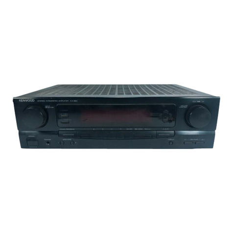
Controls
and
indicators
GRAPHIC
EQUALIZER
level
control
keys
POWER
STAND
BY
indicator
x
KENWOOD
|
ereneo
confnon
ampurrien
xc-208
Infrared
remote
control
sensor
CD
DIRECT
key
/indicator
See
page
11.
LOUDNESS
switch
Compensates
for
the
bass
in
low-volume
listening.
VOLUME
CONTROL
with
point
indicator
VOLUME
[CONTROL
GRAPHIC
EQUALIZER
(
aoHnnoa
aq,
(Hz)
60
150
400
Ik
24k
6k
15k
(Hz)
noo
ood
cGcoyv
oFeYS'by
e
co
ofRECT
LOUDNESS
eMor
ao
w
Ww iy
dace
ton
tl
or
POWER
TAPEE
(MONITOR)
TAPE!
VIGEOe
VIDEO}
(AUX)
TUNER
PHONO
BALANCE
T
Wemony
Gace
cares
Ose
|)
SS
'
ENTER
ON/OEEEAT
1
§
u
POWER
Key
TAPE
MONITOR
key
(TAPE
2)
EQ.
REC
key
P
Activates
recording
|
MEMORY
key
of
sound
processed
|
Used
to
preset
equalizer
by
the
graphic
—
patterns.
equalizer.
|
ENTER
key
|
Enters
the
equalizer
,
pattern
to
be
preset.
Input
select
keys
BALANCE
control
CALL
key
Recalls
five
types
of
preset
equalizer
patterns.
|
ON/DEFEAT
key
Switches
the
graphic
equalizer
ON/OFF.
DISPLAY
key
=
Display
window
EQUALIZER
indicator
MUTING
indicator
EQ.
REC
indicator
Input
mode/equalizer
Graphic
equalizer/
channel
display
Spectrum
analyzer
display
EQ.
MEMORY
indicator
6
Kc-209
(En)
TAPE
2
MONITOR
indicator
REMOTE
indicator
STAND
BY
mode
of
POWER
key
When
the
power
cord
of
this
system
is
plugged
into
an
AC
outlet,
the
STAND
BY
indicator
lights
up
regardless
of
the
ON/OFF
setting
of
the
POWER
key.
This
indicates
that
a
small
amount
of
current
is
being
supplied
to
the
unit
to
back
up
the
memory
contents.
This
mode
is
referred
to
as
the
STAND
BY
mode.
While
the
STAND
BY
indicator
is
lit,
the
power
of
the
system
can
be
switched
ON/OFF
from
the
remote
control
unit.
System
connections
Make
connection
as
shown
in
the
diagram
below.
When
connecting
the
related
system
components,
refer
also
to
the
instruction
manuals
of
the
related
components.
Do
not
plug
in
the
power
lead
until
all
connections
are
completed.
Turntable
Tuner
Tape
deck
1
LINE
IN——LINE
QUT:
al
AC
outlets
Refer
to
page
8.
=
To
AC
outlet
ACND~
120/P20—200V~
SWITCHED
TOTAL
ew
Max
ACHIO~10V~
=
ACz0-2uNv—
tor
switch
(Except
for
some
areas.)
SYSTEM
CONTROL
Control
amplifier
KC-209
LINE
INLINE
OUT
Cc
PLAY
|
|
a
Gor
[a
&
tL
Audio
cable
(supplied)
CD
player
comet
TT)
aes
Seece
cro
To
AC
outlet
ACIO~
jere0-200V~
UNSWITCHED
TOTAL
ImW
MAX.
(MPEDANCE
SELECTOR
LESS
THAN
ac
8a
OR
MORE
om)
Power
amplifier
KM-209
AUDIO
OUT
#
Ground
For
maximum
safety
and
minimum
interference,
connect
the
GND
terminal
to
a
good
earth
ground
if
practicable.
,
A
A
good
earth
ground
is
a
cold
water
pipe
or
a
metal stake
©
©)
driven
into
moist
earth.
However,
never
use
a
gas
pipe
for
PAUSE
yeeO
"
wi
—auc10
GUT
.
this
purpose.
\
Notes:
—
—
$$
1.
To
prevent
possible
problems,
always
disconnect
the
power
plug
or
turn
off
the
POWER
switch
of
the
power
amplifier
before
connecting
or
disconnecting
the
audio
cables.
Video
cassette
recorder
2.
When
connecting
the
audio
cables,
always
insert
the
pin
plugs
correctly
into
the
connecting
jacks.
e
Insufficient
insertion
may
result
in
no-sound
problems
or
generation
of
noise.
KC-209
(En)
7
AC
voltage
selec-
System
control
operation
Connection
Using
the
system
control
cords
provided
with
KENWOOD
system
component
models,
make
connections
as
shown
below.
(For
connections
of
the
audio
cords,
refer
to
the
“System
connections”
diagram.)
Turntable
AC
outlets
for
Australia
for
other
countries
Power
amplifier
System
control
cord
———~
Control!
amplifier
Connect
to
the
"UNSWITCHED’
outlet.
Tuner
ANTEMWA
output
sg)
fT
ANTENNA
o©
os
€
et
i
“8
ma
To
a
wall
AC
outlet
Tapedeck
CD
player
Note:
Do
not
connect
the
system
control
cord
to
the
tape
deck
connected
to
the
TAPE
2
jacks.
8
kc-209
(En)
(Ra
mR
eg
INST
a
TT
aN
Operation
By
connecting
this
unit
to
other
KENWOOD
system
components
equipped
with
SYSTEM
CONTROL
ter-
minals,
such
as
a
tuner,
tape
deck,
CD
player
and/or
turntable,
the
following
convenient
operations
will
be
available.
1.
Automatic
play
operation
When
starting
play
with
the
turntable,
tape
deck,
or
CD
player
connected
to
this
unit,
press
the
desired
input
selector
keys
on
the
amplifier.
The
turntable,
tape
deck,
or
CD
player
will
automatically
enter
play
mode.
In
the
same
way,
pressing
the
Play
key
of
the
turntable,
tape
deck,
or
CD
player
will
automatically
switch
the
input
selector
on
the
amplifier
to
the
component
on
which
the
Play
key
is
pressed.
2.
Synchro
recording
To
record
the
sound
from
the
CD
player
or
turntable
onto
a
tape
with
the
tape
deck,
press
the
CD
or
PHONO
of
the
input
selector
keys
and
load
a
CD
or
record.
Set
the
tape
deck
to
rec
pause
mode,
then
press
the
Play
(START)
key
of
the
CD
player
or
turntable.
The
tape
deck
will
start
recording
automatically,
synchronized
with
the
CD
player
or
turntable
starting
play.
For
more
details,
refer
to
the
instruction
manual
of
the
tape
deck.
3.
Remote
control
When
the
amplifier,
tuner,
tape
deck,
CD
player,
and
turntable
are
connected
via
the
system
control
cords,
these
components
can
be
controlled
from
the
remote
control
unit
supplied
with
this
unit.
poe
Foe
e
Be
sure
to
insert
the
system
control
cord
plugs
fully
into
the
SYSTEM
CONTROL
terminals.
Notes:
m™
Connection
of
the
audio
cords
and
system
control
cord
Make
sure
that
the
right
and
left
audio
cords
are
connected
correctly
as
in
the
figure.
If
the
system
control
cord
and
audio
cords
are
not
connected
properly,
the
automatic
system
governing
re-
mote
control
and
system
functions
will
not
operate.
1.
System
control
operation
of
the
unit
connected
to
the
TAPE
2
jacks
cannot
be
carried
out.
2.
For
connections
of
the
audio
cords,
refer
to
the
“System
connections”
diagram.
e
If
the
system
contro!
cords,
audio cords
and
ground
lead
cord
are
not
connected
properly,
the
automatic
system
governing
remote
control
and
system
func-
tions
will
not
operate.
3.
If
the
components
connected
to
this
unit
are
not
KEN-
WOOD
system
components,
do
not
connect
anything
to
the
SYSTEM
CONTROL
terminals.
KC-209
(En)
9
Operating
instructions
POWER
STAND
BY
indicator
KENWOOD
orenco
connor
aueirien
xo-208
MUTING
indicator
VOLUME
CONTROL
14.15
18
4,
e
ep
RECT
GRAPHIC
EQUALIZER
oHHooocag,
(Hz)
60
160
400
1k
2ak
Bk
15k
(Hz)
“
G3
—)
™
POWER
Power
STAND
GY
vineoe
a=
:
LOUONESS
a
B
mM
M
ka
JU
ww
VIOEDI
(AUX)
TUNER
onD
ore
PHONO:
MEMORY
CALL
BALANCE
€a.fEC
OIWPLAY
ENTER..ON/QEFEAT
©
O
ss
CENTER
©:
POWER
key
TAPE
MONITOR
key
(TAPE
2)
The
selected
input
source
is
displayed.
At
PON
bef
VIDEGe
VIDEO)
(AUX)
TUNER
PHONO
To
mute
the
sound
temporarily
Press
the
MUTE
key,
on
the
remote
control
unit.
e
The
MUTING
indicator
blinks,
and
the
output
is
muted.
e
When
the
MUTE
key
is
pressed
again,
the
MUT-
ING
indicator
disappears
and
the
previous
output
level
is
resumed.
The
muting
indicator
also
blinks
(for
approx.
5
seconds)
when
the
muting
function
is
engaged
immediately
after
the
power
turned
ON.
TAPE
2
is
played
in
priority
while
the
TAPE
2
indicator
is
lit.
10
Kc-209
(En)
input
select
keys
BALANCE
control
VOLUME
CONTROL
with
point
indicator
@
Basic
operation
1.
Press
the
POWER
key
to
ON.
e
The
display
lights
and
the
unit
becomes
operative.
e
Pressing
the
key
again
switches
the
power
OFF.
e@
When
the
components
are
connected
as
shown
on
page
8,
all
of
them
can
be
switched
ON/OFF
by
this
POWER
key.
.
Press
one
of
the
input
select
keys
to
select
the
input
source
to
be
played.
e
{f
the
system
control
cord
has
been
connected
to
the
selected
source
component,
it
starts
play
due
to
the
Automatic
Play
operation
feature.
With
the
Automatic
Play
operation
feature,
when
one
of
the
source
components
is
started
to
be
played,
the
corresponding
input
selector
is
automatically
switched
to
the
source.
e
The
selected
input
source
is
shown
on
the
display.
.
If
automatic
play
operation
using
the
system
con-
trol
cords
has
not
been
set,
start
playing
the
source
component
selected.
.
Adjust
the
output
level
with
the
VOLUME
CON-
TROL
knob.
e@
When
one
of
the
VOLUME
CONTROL
keys
on
the
remote
control
unit
is
pressed,
the
VOLUME
indica-
tor
blinks
and
the
VOLUME
CONTROL
knob
is
rotated.
.
Adjust
the
balance
of
the
left
and
right
output
levels
with
the
BALANCE
control.
.
Adjust
the
tone
referring
to
the
description
in
the
"Graphic
equalizer”
section.
e@
The
graphic
equalizer
effect
can
be
switched
ON/OFF
by
pressing
the
ON/DEFEAT
key.
Notes:
——_____$$$_
FFF
1.
The
CD
DIRECT
key
should
usually
be
set
to
OFF
(with
the
indicator
not
lit).
The
setting
of
the
input
select
key
is
backed
up
for
a
few
days
even
when
the
POWER
plug
is
disconnected.
After
this
period,
the
TUNER
is
automatically
selected
when
the
power
is
supplied.
.
When
the
TAPE
2
key
is
set
to
ON,
the
program
source
selected
with
input
select
key
cannot
be
heard
from
the
speakers.
To
listen
to
the
program
source
other
than
tape
deck
2,
be
sure
to
set
the
TAPE
2
key
to
OFF.
2.
KENWOOD
sreaeo
contro,
ameurien
xo-200
CD
DIRECT
key
VOLUME
CONTROL
1416
18
47
GRAPHIC
EQUALIZER
co
DIRECT
le
(Hz)
60
160
400
1k
284k
6k
15k
(Hz)
oon
onc”
=a
LOUDNESS
=
OF
o
#
a G
tA
mM
1m
iw
w
i
at
Lon
Lore
POWER
[TAPER
(MONITOR)
TAPE?
VIDEO2
VIDEOI(AUX)
TUNER
PHONO
BALANCE
MEMORY
CALL
conc
osu,
SS
CENTER
‘ON/BTAND
BY
TAPE
MONITOR
key
(TAPE
2)
TAPE
1
key
EQ.
REC
key
@
Operations
using
CD
DIRECT
key
To
enjoy
the
high
sound
quality
of
CD
with
more
fidelity:
1.
Press
the
CD
DIRECT
key.
I
ke
The
indicator
lights.
CD
DIRECT
2.
Play
the
CD
player.
e
The
CD
DIRECT
key
is
given
priority
over
the
setting
of
the
input
select
keys.
e
The
graphic
equalizer
cannot
be
used
while
the
CD
DIRECT
key
is
ON.
e
To
cancel
the
CD
DIRECT
input,
press
the
CD
DIRECT
key
again
or
press
one
of
the
input
select
keys
(except
CD
and
TAPE
2
keys).
The
input
will
be
switched
to
the
source
indicated
on
the
display.
To
listen
to
the
CD
direct
sound
while
recording
another
source:
1.
Press
the
input
select
key
of
the
source
to
be
recorded.
e
The
selected
input
source
name
is
shown
on
the
display.
2.
Play
the
source
to
be
recorded,
and
record
it
on
the
tape
deck
connected
to
the
TAPE
1
jacks.
@
When
the
EQ.
REC
key
is
pressed,
sound
to
which
the
graphic
equalizer
effect
is
applied
can
be
recorded.
3.
Press
the
CD
DIRECT
key.
4.
Play
the
CD
player.
Note:
This
function
is
available
only
when
the
components
are
connected
via
the
system
control
connection.
Input
select
keys
™@
To
record
program
source
1.
Select
the
program
source
to
be
recorded
with
the
input
select
keys
(TUNER,
CD,
PHONO,
VIDEO
1
{AUX],
VIDEO
2).
2.
Play
the
program
source.
3.
Set
tape
deck
1
and/or
tape
deck
2
to
record
mode.
4.
To
equalize
the
recording
sound,
press
the
EQ.
REC
key
and
adjust
the
GRAPHIC
EQUALIZER
controls.
Note:
______
>
es
Sound
processed
by
the
equalizer
sound
can
only
be
re-
corded
with
tape
deck
1.
m@
Dubbing
from
tape
deck
2
to
tape
deck
1
1.
Press
TAPE
2
key
and
an
input
select
key
other
than
TAPE
1.
2.
Set
tape
deck
2
to
play
and
tape
deck
1
to
record.
3.
To
equalizer
the
recording
sound,
press
the
EQ.
REC
key
and
adjust
the
GRAPHIC
EQUALIZER
controls.
Notes:
1.
Do
not
press
the
TAPE
1
input
select
key
during
dubbing.
2.
To
listen
to
the
equalized
recording
sound,
press
the
ON/DEFEAT
key.
KC-209
(En)
41
Operating
instructions
Graphic
equalizer
GRAPHIC
EQUALIZER
OoAnooeooca.
(Hz)
60
400
1k
2.4
6k
15k
(Hz)
ve
=)
(i)
=
(——)
i
POWER
MEMORY
CALL
EQ.
REC
DISPLAY
OO
ENTER
ON/DEFEAT
ON/STAND
BY
@
How
to
apply
the
equalizer
effect
to
the
sound
1.
Press
the
ON/DEFEAT
key.
e
The
EQUALIZER
indicator
lights
up.
2.
By
pressing
each
of
the
7-band
equalizer
fevel
control
keys,
create
the
equalizer
pattern
which
provides
the
desired
tone.
e
Pressing
the
upper
segment
of
an
equalizer
level
control
key
increases
the
level
of
the
frequency
band
in
+2
dB
increments
up
to
+
12
dB.
e
Pressing
the
lower
segment
of
an
equalizer
level
control
key
decreases
the
level
of
the
frequency
in
—2
dB
decrements
down
to
—12
dB.
e
For
reference
in
creating
desired
tones,
read
“Func-
tions
of
the
Graphic
Equalizer”
and
"Sound
equaliza-
tion”
sections
on
page
13.
e
|fup
to
5
equalizer
patterns
have
already
been
preset
inthe
memory,
they
can
be
recalled
in
sequence
by
pressing
the
CALL
key.
Spectrum
analyzer
display
Peak
hold
level
:
(Cowan
Signal
levels
of
frequency
bands
e
The
levels
vary
according
to
the
input
signal.
Graphic
equalizer
display
When
the
CALL
key
is
pressed,
the
recalled
preset
channel
No.
is
displayed
for
a
few
seconds.
Equalizer
pattern
12
kc-209
(En)
EQUALIZER
indicator
Graphic
equalizer/
spectrum
analyzer
display
EQ.
REC
indicator
EQ.
MEMORY
indicator
Input
mode/equalizer
channel
display
@
How
to
store
the
graphic
equalizer
patterns
This
unit
allows
you
to
store
up
to
5
equalizer
patterns
in
memory
for
instant
recall.
1.
Press
the
DISPLAY
key
to
set
the
display
to
the
graphic
equalizer
mode.
2.
Adjust
the
GRAPHIC
EQUALIZER
level
control
keys
to
obtain
the
desired
equalizer
pattern.
3.
Press
the
MEMORY
key.
The
MEMORY
indicator
lights
up
in
the
display.
4.
Within
approx.
5
seconds
after
pressing
the
MEM-
ORY
key,
press
the
CALL
key
to
select
the
desired
equalizer
channel
(EQ-1
to
EQ-5)
in
which
you
want
to
store
the
equalized
pattern.
5.
Press
the
ENTER
key
to
store
the
equalized
pattern
in
memory.
6.
To
recall
a
preset
equalizer
pattern
which
has
already
been
stored,
press
the
CALL
key.
#
Display
window
Spectrum
analyzer
display:
To
display,
press
the
DISPLAY
key
to
change
the
display
to
the
spectrum
analyzer
mode.
It
displays
the
output
level
for
each
frequency
of
the
program
source
signal
selected
by
the
input
selector
keys.
Graphic
equalizer
display:
Press
the
DISPLAY
key
to
change
the
display
to
the
graphic
equalizer
mode.
Even
while
the
spectrum
analyzer
display
mode
is
acti-
vated,
the
display
enters
the
graphic
equalizer
mode
for
approx.
5
seconds
in
the
following
cases:
1.
When
the
POWER
key
is
turned
ON.
2.
When
any
of
the
GRAPHIC
EQUALIZER
level
control
keys
is
pressed.
3.
When
the
MEMORY
key
is
pressed.
4.
When
the
CALL
key
is
pressed.
In
these
cases,
the
spectrum
analyzer
display
will
resume
approx.
5
seconds
later.
@
Functions
of
the
graphic
equalizer
fo
:
Va
Flat
Bass
Treble
Bass
Treble
Original,
or
ideal,
speaker
Actual
sound
reaching
the
sound
listener
Compensation
for
the
audio
characteristics
of
the
listening
room
The
listening
room
may
contain
several
objects.Some
of
them
reflect
sound
and
some
absorb
sound,
thus
the
sound
reaching
your
ears
is
considerably
affected
by
these
objects.
In
such
cases,
the
graphic
equalizer
can
be
used
to
adjust
the
frequency
response
of
the
room
for
a
flat
response
from
low
to
high
frequencies.
@
Low
frequencies
are
absorbed
by
beds,
chairs,
etc.
@
High
frequencies
are
absorbed
by
curtains,
screens,
etc.
@
The
room
structure
can
cause
the
low
frequencies
to
be
unclear,
or
the
sound
level
to
increase
or
decrease
de-
pending
on
the
frequency.
Adjustment
of
sound
to
your
individual
taste
When
the
reproduced
sound
contains
several
musical
in-
struments
and
voices,
the
graphic
equalizer
allows
you
to
enhance
or
attenuate
the
sound
of
specific
instruments
or
voices.
Sound
equalization
©
Super
bass
range
(60
Hz)
When
this
control
is
moved
up,
the
bass
instrument
(dou-
ble
bass,
bass
drums,
or
pipe
organ,
etc.)
sound
is
in-
creased.
When
the
super
bass
sound
is
boomy,
move
this
con-
trol
down,
®@
Bass
range
(150
Hz)
Usually,
the
listening
room
resonance
frequency
is
in
this
range.
To
eliminate
bass
resonance,
move
this
control
down
®
Mid-bass
range
(400
Hz)
This
range
is
the
basis
of
music.
Whether
the
sound
is
rich
or
not,
depends
on
this
range.
When
the
playback
sound
is
not
so
good,
move
this
control
up.
@
Mid
range
(1
kHz)
When
this
control
is
moved
up
or
down,
the
baritone
or
soprano
voice
is
emphasized/de-emphasized.
This
range
is
related
to
the
‘‘presence’’
of
music.
®
Mid-high
range
(2.4
kHz)
This
range
is
related
to
stimulous
and
metallic
sound.
When
this
range
is
well
compensated,
vivid
sound
can
be
obtained.
®@
High
range
(6
kHz)
This
frequency
range
is
related
to
the
hardness
of
the
sound.
When
this
control
is
moved
up,
strings
or
brass
instruments,
such
as
flutes
or
piccolos,
are
emphasized.
When
the
control
is
moved
down,
the
sound
will
be
more
soothing.
@
Super
high
range
(15
kHz)
This
frequency
range
is
related
to
the
details
of
the
music.
When
this
control
is
moved
up,
super
high
frequency
instruments,
such
as
triangles
or
cymbals,
are
empha-
sized,
resulting
in
wide
sound
and
echoes.
KC-209
(En)
13
ane
aisha
caeallcied
nn
eilcitieaenon
picked
cana
Remote
control
operation
@
Loading
batteries
into
the
remote
con-
trol
unit
1.
Remove
the
battery
cover.
While
gently
pressing
the
battery
cover
located
on
the
rear
of
the
remote
control
unit,
open
it
in
the
direction
of
the
arrow.
s
OO
2.
Insert
four
RO3
size
batteries.
Take
care
to
respect
the
battery
polarity
(+,
—).
Note;
———_______
The
batteries
provide
are
to
be
used
for
checking
the
remote
control
operations.
Their
service
life
may
be
short.
@
Battery
replacement
1.
If
the
TRANSMIT
indicator
will
not
light
up
when
an
operation
key
is
pressed,
the
batteries
may
be
exhausted.
In
this
case,
replace
them
with
new
batteries.
It
is
recommended
to
use
alkaline
batter-
ies
(LRO3)
with
long
life.
2.
The
programmed
contents
are
not
immediately
lost
when
the
batteries
are
removed
for
replacement.
However,
they
could
be
lost
if
the
unit
is
left
without
batteries
for
more
than
3
minutes.
In
such
a
case,
the
programming
should
be
per-
formed
again.
The
function
signals
of
the
non-
learning,
or
fixed,
keys
are
not
lost
even
in
this
case.
Note;
————______
SSF
Avoid
using
old
and
new
batteries
together,
as
this
may
cause
corrosion.
14
Kc-209
(En)
@
Operation
1.
Connect
the
power
plug
of
the
amplifier
to
an
AC
outlet.
e
This
enters
the
amplifier
to
power
standby
mode.
2.
Press
the
POWER
key
on
the
remote
control
unit
or
the
POWER
key
on
the
amplifier.
e
This
unit
enters
the
amplifier
to
power
ON
mode.
3.
Operate
with
the
keys
of
the
remote
control
unit.
e
After
pressing
one
of
the
operation
keys,
when
the
next
operation
is
required,
press
the
next
operation
key
firmly
after
an
approx.
1
second
interval.
if
the
next
operation
key
is
pressed
immediately
after
the
previous
key,
misoperation
may
result.
@
Usable
range
of
the
remote
control
unit
The
usable
range
of
the
remote
control
unit
may
differ
with
temperature,
humidity,
or
operating
conditions.
However,
it
is
defined
approximately
as
shown
in
the
figure
below:
For
controlling
the
amplifier,
TV
and
VCR
emote
control
sensor
of
the
amplifier,
TV
or
VCR
6m
The
signal
transmission
system
used
by
this
remote
control
unit
is
the
infrared
control
system.
Note:
Malfunction
may
occur
in
case
direct
sunlight
or
the
light
of
a
high
frequency
lighting
fluorescent
lamp
enters
the
remote
control
light
recepter.
In
such
a
case,
change
the
installation
position
of
the
unit
so
that
the
malfunction
does
not
occur.
The
remote
control
unit
(RC-120)
is
capable
of
the
remote
control
of
this
unit
as
well
as
other
KENWOOD
system
components
connected
to
this
unit
via
system
control
cords,
KENWOOD
*VCR
and
*TV.
In
addition,
it
is
also
possible
to
program
the
remote-controllable
functions
of
other
A/V
components
in
the
memory
of
RC-120,
making
it
a
multi-purpose
remote
controller
for
the
whole
of
your
system.
Names
and
operation
of
controls
TRANSMIT
indicator
Blinks
when
a
remote
control
signal
is
transmitted.
LEARN
indicator
LEARN/USE
select
Mode
switch
switch
TAPE/VIDEO
Set
to
the
USE
position
Ee
for
normal
operation.
nee
Gi:
Gl
be
Oo
Ww)
ce
I
TAPE/VIDEO
keys
co/voP
TV/VIDEO
CD/VDP
keys
GH es
co
Free
key
i]
nooo)
mnoOoogm
TV
keys
fWvibEG
=
wig,
oy
oleae]
:
OOo
S|
SYSTEM
MEMORY
keys
-
Numeric
keys
ie
TUNER
keys
PHONO
keys
I
SURROUND
keys
(AUX)
TUNER
VIDEO
2
DELAY
TIME
keys
Input
select
keys
CJC)
TAPE
1
VIDEO
3]}
CENTER
LEVEL
mean
vever
Ceo
[——
VOLUME
CONTROL
keys
POWER
MUTE
POWER
keys
==)
SCO
AUDIO
TV
VIDEO
KENWOOD
UNIVERSAL
PROGRAMMABLE
REMOTE
CONTROL
UNIT
;
*IMPORTANT:
This
option
may
not
be
available
in
some
areas.
For
details
on
options,
consult
your
dealer.
RC-120
m@
Remote
control
operation
1.
The
whole
of
the
keys
can
be
used
in
three
ways
(three
sides)
by
selecting
the
mode
switch
position.
The
AUDIO
and
VIDEO
sides
contains
the
initial
programming
of
KENWOOD-original
remote-control
codes.
(Please
refer
to
“Original
function
of
keys”
on
page
16.)
VIDEO
e
AUDIO
position:
For
the
remote
control
of
KENWOOD
system
components
and
KENWOOD
TV.
AUDIO...
AUX
@
VIDEO
position:
For
the
remote
control
of
KENWOOD
VCR,
KENWOOD
TV
and
part
of
KENWOOD
system
components.
Mode
switch
@
AUX
position
:
All
keys
are
available,
that
is,
able
to
store
the
programming
of
other
remote
control
functions.
2.
The
remote
control
functions
of
other
A/V
components
can
also
be
programmed
under
the
keys
on
the
AUDIO
and
VIDEO
sides
as
well
as
on
the
AUX
side.
However,
when
any
information
is
programmed
under
a
key
on
the
AUDIO
or
VIDEO
side,
the
original
function
pre-programmed
under
that
key
becomes
unavailable.
3.
For
the
programming
method,
please
refer
to
page
19.
KC-209
(En)
15
ssmconeecu
ad
asin
tate
DSi
eta
eae
Remote
control
operation
@
Original
function
of
keys
Set
to
the
USE
position.
TRANSMIT
TAPE/
VIDEO.
@
LEARN/USE
select
switch
ang
Mode
switch
unio),
Set
to
the
AUDIO
ian
or
VIDEO.
If
any
of
the
following
KENWOOD
component
mod-
els
is
used,
this
remote
control
unit
cannot
be
used
to
control
the
CD
manual
search
function
or
to
make
entries
with
the
numeric
keys
(1
to
O
and
+10):
*
DP-M97,
DP-57,
DP-47
@
TAPE/VIDEO
control
keys
TAPE
deck
control
keys
(Mode
switch:
AUDIO)
TAPE/VIDEO
Seo
oom
VIDEO
CH.
Use
the
A/B
select
switch
to
specify
the
A
deck
or
B
deck
of
a
dual-transport
double
cassette
deck.
The
darkened
keys
(marked
"
[<=
4
”)
do
not
function
at
this
time.
Note,
AAA
When
it
is
necessary
to
press
the
fast
forward
key
after
the
rewind
key,
be
sure
to
press
the
stop
key
before
pressing
the
fast
forward
key.
16
kc-209
(En)
oo
co
op
ca
ey
oS
eal
Daw
oo
oma
ooOD
GIO)
Ty/vipgO
—Tv
CHI
1
Fy
SURROUND
|
=
ce
ms
Ot
=
ey
a
oo
Sj
2
ey
ical
Ley
:
CONTROL
seeeu
KENWOOD
UNIVERSAL
PROGRAMMABLE
REMOTE
CONTROL
UNIT
RAC-120
VIDEO
deck
control
keys
(Mode
switch:
VIDEO)
VIDEO
CH.
Ge]
ee)
OI
&!)
The
darkened
keys
(marked
”
[=
time.
When
remotely
controlling
the
*KV-D957S
from
KEN-
WOOD
(for
U.S.A.
and
military),
set
the
A/B
select
switch
to
A.
VIDEO
CH
keys:
Pressing
the
[4A]
key
shifts
the
channel
tuned
on
the
VIDEO
deck
upward,
and
pressing
the
[V7]
key
shifts
if
downward.
TV/VIDEO
key:
Every
time
this
key
is
pressed,
the
output
from
the
video
deck
is
switched
between
the
TV
channel
RF
output
and
video
output.
}")
do
not
function
at
this
m@
CD
player
control
keys
CD/VOP
El
Gs
oe
Go
a
oS
oo
Mode
switch:
AUDIO
or
VIDEO
These
keys
allow
the
same
operations
as
the
keys
with
the
same
names
on
the
CD
player.
The
DISC
key
is
for
use
exclusively
with
a
multiple
CD
player.
Pressing
the
DISC
key
allows
one
of
DISC
1
to
DISC
6
to
be
selected
in
the
following
cycle.
DISC
Poe
m@
Numeric
keys
(1
to
0)
Om
oC
eI)
CC
Co
oo
ee)
Mode
switch:
AUDIO
When
the
CD
or
TUNER
input
selector
key
is
selected,
these
keys
can
be
used
in
place
of
the
numeric
keys
on
the
CD
player
or
tuner,
respectively.
Mode
switch:
VIDEO
The
numeric
keys
can
be
used
in
placed
of
the
TV
channel
select
keys.
m@
TV
set
control
keys
cy
—
TV
CH
abs
TV
VOL
Mode
switch:
AUDIO
or
VIDEO
TV
VOL
keys:
Pressing
the
[2]
key
increases
the
volume
of
the
TV
set.
and
pressing
the
[~
]
key
decreases
it.
TV
CH
keys:
Pressing
the
[A]
key
shifts
the
channel
tuned
on
the
TV
set
upward,
and
pressing
the
[7
|
key
shifts
it
downward.
TV/VIDEO
key:
Every
time
this
key
is
pressed,
the
input
to
the
TV
set
is
switched
between
the
TV
signal
and
the
external
video
signal.
@
TUNER
control
keys
Mode
switch:
AUDIO
or
VIDEO
These
keys
have
the
same
functions
as
the
keys
with
the
same
names
on
the
tuner
unit.
@
Turntable
(PHONO)
control
keys
Mode
switch:
AUDIO
or
VIDEO
The
play
[=]
and
stop
[ml]
keys
are
provided.
@
SYSTEM
MEMORY
keys
SYSTEM
MEMORY
Mode
switch:
AUDIO
or
VIDEO
These
keys
are
not
used
with
this
unit.
KC-209
(En)
17
Remote
control
operation
@
Equalizer
key
Mode
switch:
AUDIO
or
VIDEO
Every
time
the
EQ.
key
is
pressed,
the
equalizer
of
this
unit
can
be
switched
ON/DEFEAT
or
preset
equalizer
patterns
can
be
changed
over
in
the
following
cycle.
~~
£02-
- -
Sino
DEFEAT
ON
EQ-1
PHONO
VIDEO
1
(AUX)
TUNER
VIDEO
2
TAPE
1
VIDEO
3
TAPE
2
VIDEO
4
Co
Mode
switch:
AUDIO
or
VIDEO
These
keys
have
the
same
functions
as
the
input
selector
keys
of
this
unit.
The
VIDEO
3
and
4
keys
are
not
used
with
this
unit.
m™
SURROUND
keys
&
MENU
ON
SCREEN
key
CENTER
SURROUND
MODE
MODE
BYPASS
TEST
TONE
MENU
ON/OFF
MODE
ONSCREEN
DELAY
TIME
Mode
switch:
AUDIO
or
VIDEO
These
keys
are
not
used
with
this
unit.
18
Kc-209
(En)
@
Volume
level
keys
CENTER
LEVEL
VOLUME
REAR
LEVEL__
CONTROL.
Mode
switch:
AUDIO
or
VIDEO
VOLUME
CONTROL
keys:
Pressing
the
[A]
key
rotates
the
VOLUME
CONTROL
on
the
main
body
of
the
amplifier
clockwise
to
increase
the
volume,
and
pressing
the
[7
]
key
rotates
it
counterclock-
wise
to
decrease
the
volume.
CENTER
LEVEL
keys:
These
keys
are
not
used
with
this
unit.
REAR
LEVEL
keys:
These
keys
can
be
used
in
place
of
the
VOLUME
CONTROL
on
the
AV
SURROUND
PROCESSOR
(*SS-7
9).
MUTE
key:
The
MUTE
key
is
not
provided
on
the
main
body.
Muting
can
be
controlled
only
from
the
remote
control.
m
POWER
keys
Sse)
TV
VIDEO
Mode
switch:
AUDIO
or
VIDEO
AUDIO
key:
Switches
the
power
of
the
amplifier
to
ON/STANDBY
(OFF).
TV
key:
Switches
the
power
of
the
TV
set
to
ON/STANDBY
(OFF).
VIDEO
key:
Switches
the
power
of
the
video
deck
to
ON/STANDBY
(OFF).
*IMPORTANT:
This
option
may
not
be
available
in
some
areas.
For
details
on
options,
consult
your
dealer.
a
a
NA
A
oe
LEARN
jo
LEARN/USE
=
TRANSMIT
select
switch
Other
remote
control
unit
;
geedied
ot
a
z
‘80
og:
8
8
8.08
80,8
alo
DHONO
D8
a
a6S
pf
8
80
OO
He
18
O10
BO
AO
OO
0000}
Example:
To
program
the
REPEAT
key
of
the
other
remote
control
unit
Hold
the
REPEAT
key
depressed
Transmitted
Za.
<a
a
q
q
gi
Rt)
OO
os oe
(ce
cal
oe
oC
iaa
KENWOOO
=
6
Blinks
REPEAT
function
is
stored
under
this
key
@
To
program
the
remote
control
func-
tions
of
other
remote
control
units
into
the
RC-120
Most
audio/video
components
use
the
same
infrared
remote
control
coding
system.
Therefore,
the
RC-120
can
memorize
most
of
the
functions
of
other
remotely-con-
trolled
components.
Please
read
this
manual
and
the
instruction
manuals
provided
with
your
other
A/V
compo-
nents
carefully
before
programming
the
remote
control
functions
of
the
other
components.
1.
Set
the
LEARN/USE
select
switch
to
the
LEARN
position,
and
set
the
mode
switch
to
the
desired
position.
2.
Place
the
RC-120
and
the
other
remote
control
unit
so
that
their
heads
(transmission
ends)
face
each
other.
(Leave
a
distance
between
the
units
of
about
2
~
5
or
0.8
~
2
inches.)
3.
Press
one
of
the
learning
keys
on
the
RC-120.
The
LEARN
indicator
will
light.
4.
Press
the
key
to
be
programmed
on
the
other
remote
control
unit
and
hold
it
depressed.
5.
When
the
LEARN
indicator
on
the
RC-120
blinks
twice
and
then
goes
out,
the
programming
opera-
tion
is
completed.
When
the
programming
opera-
tion
is
completed,
release
your
finger
from
the
key
on
the
other
remote
control
unit.
e@
Toprogram
other
remote
control
function,
repeat
the
procedure
outlined
in
steps
3.
to
5.
Note:
Be
sure
to
hold
the
key
to
be
programmed
on
the
other
remote
control
unit
depressed
until
the
LEARN
indicator
goes
out.
KC-209
(En)
19
Remote
control
operation
(=
]
tRaNsmir
Mode
LEARN/USE
switch
select
switch
——=
Set
to
USE.
(5)
transmit
<i
Set
to
USE.
Reset
key
Overlay
sheet
Notes:
1.
If
the
optical
output
level
of
the
other
remote
control
unit
is
high,
programming
may
not
be
carried
out
correctly.
If
this
occurs,
separate
the
RC-120
and
the
other
remote
control
unit
by
a
greater
distance
and
perform
the
programming
procedure
again.
2.
If
the
LEARN
and
TRANSMIT
indicators
blink
simultane-
ously
during
programming,
this
indicates
either
that
the
key
being
programmed
cannot
be
programmed
or
that
programming
has
not
been
performed
completely.
If
this
occurs,
perform
the
programming
procedure
again.
3.
Remote
control
functions
using
specially-coded
signals
or
signals
other
than
infrared
signals
cannot
be
programmed.
20
xc-209
(En)
To
check
the
programmed
contents
during
programming
1.
Check
that
the
LEARN/USE
select
switch
is
in
the
USE
position.
2.
Press
the
key
to
be
checked.
3.
Verify
that
the
component
to
be
operated
works
correctly.
@
To
change
the
programmed
contents
Perform
the
programming
operation
again.
The
previously
programmed
contents
will
be
canceled
automatically,
and
the
newly
programmed
contents
will
be
maintained
in
memory.
@
Normal
operation
of
the
remote
con-
trol
unit
1.
Set
the
LEARN/USE
select
switch
to
the
USE
position.
2.
Press
a
key
under
which
another
remote
control
function
has
been
programmed.
The
TRANSMIT
indicator
blinks
and
the
target
component
operates
as
intended.
@To
erase
the
entire
programmed
contents
With
a
single
procedure,
you
can
erase
all
of
the
remote
contro!
functions
which
have
been
programmed
under
keys
in
each
mode
(AUDIO,
VIDEO,
and
AUX).
1.
Set
the
LEARN/USE
select
switch
to
the
LEARN
position.
2.
Press
a
programmable
key
(any
programmable
key
may
be
pressed).
e
The
LEARN
indicator
lights.
3.
Remove
the
battery
cover
from
the
back
of
the
remote
control
unit.
4.
Press
the
reset
key
located
inside
the
battery
case
using
the
tip
of
a
ball-point
pen
or
similar
instrument.
e
All
of
the
programmed
contents
are
erased
and
the
remote
control
unit
returns
to
its
initial
condition.
@
Overlay
sheet
The
provided
overlay
sheet
offers
a
convenient
way
to
record
and
recall
the
contents
programmed
under
the
various
operation
keys.
Write
the
programmed
key
contents
on
the
overlay
sheet
with
an
oil-based
felt-tipped
marker
or
pencil.
To
erase,
use
a
conventional
eraser.
Programming
is
also
impossible
when
the
RC-120's
memory
capacity
becomes
full.
4.
The
LEARN
indicator
goes
out
30
seconds
after
a
learning
(programmable)
key
is
pressed.
After
this,
programming
is
impossible.
To
continue
programming,
press
the
learn-
ing
(programmable)
key
again.
5.
When
two
or
more
learning
(programmable)
keys
are
pressed
at
the
same
time,
the
remote
control
function
of
the
other
remote
control
unit
will
be
stored
under
the
key
which
was
pressed
last.
6.
Do
not
program
the
remote
control
functions
of
equip-
ment
other
than
A/V
components,
such
as
air
condi-
tioners,
etc.

Other Kenwood Amplifier manuals

Kenwood XXV-03A User manual

Kenwood

Kenwood XXV-03A User manual

Kenwood KAC-PS621 User manual

Kenwood

Kenwood KAC-PS621 User manual

Kenwood KAC-5202 User manual

Kenwood

Kenwood KAC-5202 User manual

Kenwood KAC-520 User manual

Kenwood

Kenwood KAC-520 User manual

Kenwood KM-X1 User manual

Kenwood

Kenwood KM-X1 User manual

Kenwood KAC-6404 User manual

Kenwood

Kenwood KAC-6404 User manual

Kenwood KAC-8402 User manual

Kenwood

Kenwood KAC-8402 User manual

Kenwood TL-120 User manual

Kenwood

Kenwood TL-120 User manual

Kenwood KA-894 User manual

Kenwood

Kenwood KA-894 User manual

Kenwood X301-4 User manual

Kenwood

Kenwood X301-4 User manual

Kenwood KAC-929 User manual

Kenwood

Kenwood KAC-929 User manual

Kenwood KAC-823 User manual

Kenwood

Kenwood KAC-823 User manual

Kenwood KA-880SD User manual

Kenwood

Kenwood KA-880SD User manual

Kenwood KAF-1010 User manual

Kenwood

Kenwood KAF-1010 User manual

Kenwood KAC-624 User manual

Kenwood

Kenwood KAC-624 User manual

Kenwood XXV-02A - 25th Anniversary Products... User manual

Kenwood

Kenwood XXV-02A - 25th Anniversary Products... User manual

Kenwood KAC959 - Amplifier User manual

Kenwood

Kenwood KAC959 - Amplifier User manual

Kenwood KAC-624 User manual

Kenwood

Kenwood KAC-624 User manual

Kenwood KAC X40 - eXcelon Amplifier User manual

Kenwood

Kenwood KAC X40 - eXcelon Amplifier User manual

Kenwood KAC-PS401M User manual

Kenwood

Kenwood KAC-PS401M User manual

Kenwood KA-9100 User manual

Kenwood

Kenwood KA-9100 User manual

Kenwood KAC-PS702EX User manual

Kenwood

Kenwood KAC-PS702EX User manual

Kenwood KAC-M3004 User manual

Kenwood

Kenwood KAC-M3004 User manual

Kenwood KAC-X10D - eXcelon Amplifier User manual

Kenwood

Kenwood KAC-X10D - eXcelon Amplifier User manual

Popular Amplifier manuals by other brands

Nova Electronics Aquapower user manual

Nova Electronics

Nova Electronics Aquapower user manual

Electro-Voice CP-Series Power Amps CP1800 owner's manual

Electro-Voice

Electro-Voice CP-Series Power Amps CP1800 owner's manual

Pioneer M-AX10 Service manual

Pioneer

Pioneer M-AX10 Service manual

Classe Audio CAV-100 owner's manual

Classe Audio

Classe Audio CAV-100 owner's manual

Magnat Audio POWER CORE TWO Owner's manual/warranty document

Magnat Audio

Magnat Audio POWER CORE TWO Owner's manual/warranty document

Fender '57 Deluxe owner's manual

Fender

Fender '57 Deluxe owner's manual

Crate VC-50H owner's manual

Crate

Crate VC-50H owner's manual

Technics SU-8055 - service Service manual

Technics

Technics SU-8055 - service Service manual

icon Audio HP 205D manual

icon Audio

icon Audio HP 205D manual

AUSTRALIAN MONITOR AMC+60 Installation and operation manual

AUSTRALIAN MONITOR

AUSTRALIAN MONITOR AMC+60 Installation and operation manual

Cyrus CYRUS 6 Service manual

Cyrus

Cyrus CYRUS 6 Service manual

Genz Benz NEOX400-210T owner's manual

Genz Benz

Genz Benz NEOX400-210T owner's manual

Bose AmPlus 50 manual

Bose

Bose AmPlus 50 manual

Pioneer SR-202W Service manual

Pioneer

Pioneer SR-202W Service manual

AMX NMX-ENC-N2151 instruction manual

AMX

AMX NMX-ENC-N2151 instruction manual

Jetter JetWeb JetMove 203-230 user manual

Jetter

Jetter JetWeb JetMove 203-230 user manual

IRF IRAUDAMP6 user manual

IRF

IRF IRAUDAMP6 user manual

Tektronix 3240 user guide

Tektronix

Tektronix 3240 user guide

manuals.online logo
manuals.online logoBrands
  • About & Mission
  • Contact us
  • Privacy Policy
  • Terms and Conditions

Copyright 2025 Manuals.Online. All Rights Reserved.