manuals.online logo
Brands
  1. Home
  2. •
  3. Brands
  4. •
  5. Behringer
  6. •
  7. Noise Reduction Machine
  8. •
  9. Behringer Denoiser SNR2000 User manual

Behringer Denoiser SNR2000 User manual

Other manuals for Denoiser SNR2000

1

Popular Noise Reduction Machine manuals by other brands

dbx 222 instruction manual

dbx

dbx 222 instruction manual

dbx 180 owner's manual

dbx

dbx 180 owner's manual

Roland Boss NS-50 owner's manual

Roland

Roland Boss NS-50 owner's manual

Vallox Vallox 245 MV VKL installation instructions

Vallox

Vallox Vallox 245 MV VKL installation instructions

CAP Ground Control manual

CAP

CAP Ground Control manual

Dolby Laboratories 430 Series Installation and operating instructions

Dolby Laboratories

Dolby Laboratories 430 Series Installation and operating instructions

dbx 122 instruction manual

dbx

dbx 122 instruction manual

HRS M3X2 quick start guide

HRS

HRS M3X2 quick start guide

dbx SNR 1 instruction manual

dbx

dbx SNR 1 instruction manual

Ashly SC33 product manual

Ashly

Ashly SC33 product manual

ESOTERIC SOUND SURFACE NOISE REDUCER operating manual

ESOTERIC SOUND

ESOTERIC SOUND SURFACE NOISE REDUCER operating manual

Teac AN-80 Service manual

Teac

Teac AN-80 Service manual

West Mountain Radio CLRdsp ClearSpeech user manual

West Mountain Radio

West Mountain Radio CLRdsp ClearSpeech user manual

Marpac DohmBasic SleepMate user manual

Marpac

Marpac DohmBasic SleepMate user manual

BBE Sonic Maximizer + Noise Reduction 362NR user manual

BBE

BBE Sonic Maximizer + Noise Reduction 362NR user manual

dbx 187 user manual

dbx

dbx 187 user manual

Pro-Ject Audio Systems Vinyl NRS Box S3 user manual

Pro-Ject Audio Systems

Pro-Ject Audio Systems Vinyl NRS Box S3 user manual

Rocktron HUSH Ultra instruction manual

Rocktron

Rocktron HUSH Ultra instruction manual

manuals.online logo
manuals.online logoBrands
  • About & Mission
  • Contact us
  • Privacy Policy
  • Terms and Conditions

Copyright 2025 Manuals.Online. All Rights Reserved.

DENOISER® SNR2000
Version 2.3 June 2002
Users Manual
www.behringer.com
ENGLISH
2
DENOISER SNR2000
This symbol, where er it appears, alerts
you to the presence of uninsulated
dangerous oltage inside the enclosure
 oltage that may be sufficient to
constitute a risk of shock.
This symbol, where er it appears, alerts
you to important operating and
maintenance instructions in the
accompanying literature. Read the
manual.
SAFETY INSTRUCTIONS
CAUTION: To reduce the risk of electrical shock, do not remo e
the co er (or back). No user ser iceable parts inside;
refer ser icing to qualified personnel.
WARNING: To reduce the risk of fire or electrical shock, do not
expose this appliance to rain or moisture.
DETAILED SAFETY INSTRUCTIONS:
All the safety and operation instructions should be read before the appliance is operated.
Retain Instructions:
The safety and operating instructions should be retained for future reference.
Heed Warnings:
All warnings on the appliance and in the operating instructions should be adhered to.
Follo instructions:
All operation and user instructions should be followed.
Water and Moisture:
The appliance should not be used near water (e.g. near a bathtub, washbowl, kitchen sink, laundry tub, in a wet
basement, or near a swimming pool etc.).
Ventilation:
The appliance should be situated so that its location or position does not interfere with its proper entilaton. For
example, the appliance should not be situated on a bed, sofa rug, or similar surface that may block the
entilation openings: or placed in a built-in installation, such as a bookcase or cabinet that may impede the
flow of air through the entilation openings.
Heat:
The appliance should be situated away from heat sources such as radiators, heat registers, sto es, or other
appliances (including amplifiers) that produce heat.
Po er Source:
The appliance should be connected to a power supply only of the type described in the operating instructions
or as marked on the appliance.
Grounding or Polarization:
Precautions should be taken so that the grounding or polarization means of an appliance is not defeated.
Po er-Cord Protection:
Power supply cords should be routed so that they are not likely to be walked on or pinched by items placed
upon or against them, paying particular attention to cords and plugs, con enience receptacles and the point
where they exit from the appliance.
Cleaning:
The appliance should be cleaned only as recommended by the manufacturer.
Non-use Periods:
The power cord of the appliance should be unplugged from the outlet when left unused for a long period of time.
Object and Liquid Entry:
Care should be taken so that objects do not fall and liquids are not spilled into the enclosure through openings.
Damage Requiring Service:
The appliance should be ser iced by qualified ser ice personnel when:
- the power supply cord or the plug has been damaged; or
- objects ha e fallen, or liquid has been spilled into the appliance; or
- the appliance has been exposed to rain; or
- the appliance does not appear to operate normally or exhibits a marked change in performance; or
- the appliance has been dropped, or the enclosure damaged.
Servicing:
The user should not attempt to ser ice the appliance beyond that which is described in the Operating Instructions.
All other ser icing should be referred to qualified ser ice personnel.
3
DENOISER SNR2000
FOREWORD
Dear Customer,
Welcome to the team of DENOISER users and thank you ery much for expressing your confidence in
BEHRINGER products by purchasing the SNR2000.
It is one of my most pleasant tasks to write this letter to you, because it is the culmination of many months of
hard work deli ered by our engineering team to reach a ery ambitious goal: making an outstanding de ice
that will become a standard tool used by studios and P.A. companies. The task to design the DENOISER
certainly meant a great deal of responsibility, which we assumed by focusing on you, the discerning user and
musician. It also meant a lot of work and night shifts to accomplish this goal. But it was fun, too. De eloping a
product usually brings a lot of people together, and what a great feeling it is when e erybody who participated
in such a project can be proud of what we e achie ed.
It is our philosophy to share our joy with you, because you are the most important member of the BEHRINGER
family. With your highly competent suggestions for new products you e greatly contributed to shaping our
company and making it successful. In return, we guarantee you uncompromising quality (manufactured
under ISO9000 certified management system) as well as excellent technical and audio properties at an
extremely affordable price. All of this will enable you to fully unfold your creati ity without being hampered by
budget constraints.
We are often asked how we are able to produce such high-grade de ices at such unbelie ably low prices. The
answer is quite simple: its you, our customers! Many satisfied customers mean large sales olumes enabling
us to get better conditions of purchase for components, etc. Isnt it only fair to pass this benefit back to you?
Because we know that your success is our success too!
I would like to thank all people whose help on Project DENOISER has made it all possible. E erybody has
made ery personal contributions, starting from the designers of the unit ia the many staff members in our
company to you, the user of BEHRINGER products.
My friends, its been worth the trouble!
Thank you ery much,
Uli Behringer
4
DENOISER SNR2000
SNR2000
DENOISER®
Professional and all-purpose single-ended noise reduction system
sTAC (Transient Attack Control) dynamic filters respond accurately to signals with fast attacks
sAuto-filter circuitry for automatic sliding filters
sIRC (Interacti e Ratio Control) downward expander for inaudible noise reduction during signal pauses
sAccurate gain reduction and cut-off frequency meters
sDual mono or true stereo couple function
sSer o-balanced inputs and outputs on XLR and 1/4" TRS connectors
sRelay-controlled hard bypass with auto-bypass function during power failure (failsafe relay)
sCut-in delay to a oid switch-on thumps
sUltra low-noise audio operational amplifiers offer outstanding sound performance
sHigh-quality detented potentiometers and Illuminated switches
sHigh-performance output transformer BEHRINGER OT-1 retrofitable
sManufactured under ISO9000 certified management system
5
DENOISER SNR2000
TABLE OF CONTENTS
1. INTRODUCTION..................................................................................................................... 6
1.1 The design concept ......................................................................................................................... 6
1.2 Before you begin ............................................................................................................................. 7
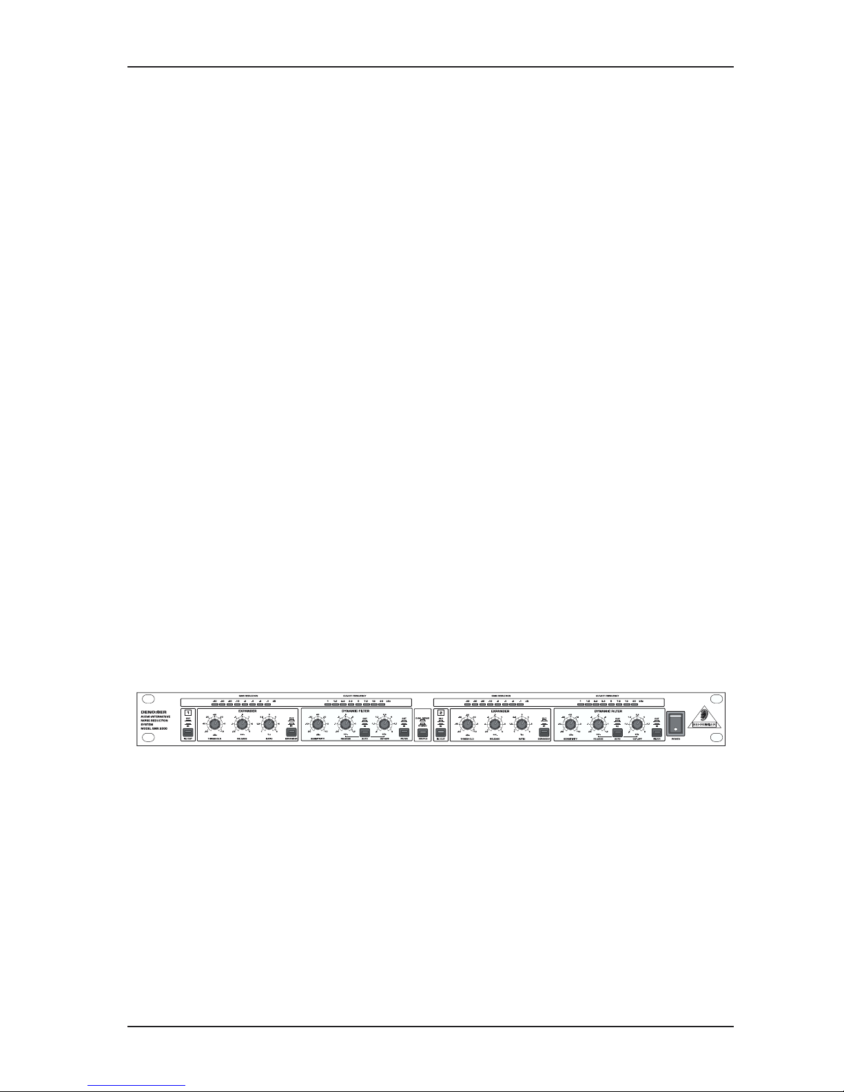
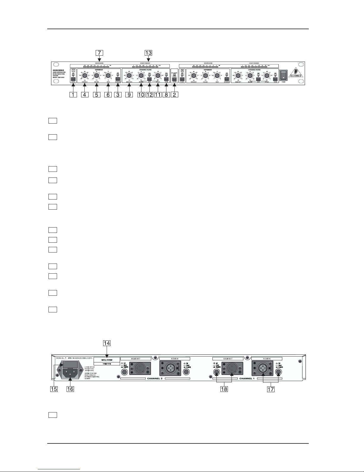
1.3 Control elements ............................................................................................................................. 7
1.3.1 Front panel ........................................................................................................................... 8
1.3.2 Rear panel ............................................................................................................................ 8
2. OPERATION ............................................................................................................................ 9
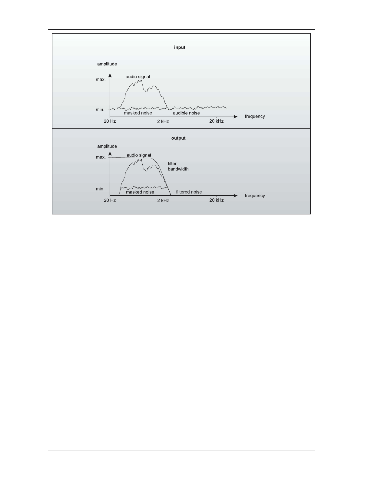
2.1 Operation of the filter section........................................................................................................... 9
2.1.1 The masking effect ................................................................................................................ 9
2.1.2 The dynamic low-pass filter ................................................................................................... 9
2.2 The TAC filter of the DENOISER .................................................................................................... 10
2.2.1 SENSITIVITY control ............................................................................................................ 11
2.2.2 CUT OFF control .................................................................................................................. 11
2.2.3 RELEASE control ................................................................................................................ 11
2.2.4 AUTO switch....................................................................................................................... 12
2.2.5 FREQUENCY meter ........................................................................................................... 12
2.3 Operation of the expander section ................................................................................................. 12
2.4 The IRC expander of the DENOISER ............................................................................................. 13
2.4.1 THRESHOLD control .......................................................................................................... 14
2.4.2 RELEASE control ............................................................................................................... 14
2.4.3 RATIO control ..................................................................................................................... 14
2.4.4 GAIN REDUCTION meter .................................................................................................... 14
2.5 The COUPLE function ................................................................................................................... 15
3. APPLICATIONS ..................................................................................................................... 15
3.1 Initial settings of the DENOISER ................................................................................................... 15
3.2 Studio applications ........................................................................................................................ 16
3.2.1 Noise reduction during playback ......................................................................................... 16
3.2.2 Noise reduction during recording ......................................................................................... 16
3.2.3 Reducing noise on subgroups, monitor and effects buses ................................................... 17
3.2.4 Noise reduction for effects de ices ...................................................................................... 18
3.2.5 Noise reduction during tape duplication ............................................................................... 18
3.2.6 Noise reduction for instruments ........................................................................................... 18
3.2.7 Reducing noise in P.A. systems ......................................................................................... 19
3.2.8 Noise reduction in Hi-Fi and ideo applications .................................................................... 19
4. TECHNICAL BACKGROUND .............................................................................................. 20
4.1 What are audio dynamics? ........................................................................................................... 20
4.2 Compressors/limiters .................................................................................................................... 21
4.3 Expanders/noise gates ................................................................................................................. 21
4.4 Downward expansion .................................................................................................................... 22
4.5 Noise as physical phenomenon..................................................................................................... 22
4.6 Companders ................................................................................................................................. 22
4.7 The single-ended principle ........................................................................................................... 23
5. INSTALLATION ..................................................................................................................... 23
5.1 Rack mounting .............................................................................................................................. 23
5.2 Audio connections ........................................................................................................................ 23
6. SPECIFICATIONS ................................................................................................................. 24
7. WARRANTY ........................................................................................................................... 26
6
DENOISER SNR2000
1. INTRODUCTION
Thank you ery much for expressing your confidence in BEHRINGER products by purchasing the BEHRINGER
DENOISER SNR2000.
Electrical noise is still one of the most unpleasant problems in the field of electro-acoustics. The basic noise
produced by a single unit is not considered to be annoying. The combination of se eral instruments, effects
de ices and tape machines, howe er, results in a drastic increase in noise le el. This requires the use of a
noise reduction system.
Conventional noise reduction systems
Con entional noise reduction systems often suffer from se eral percei able drawbacks: either the noise
reduction process deteriorates the signal by cutting the high-frequency portions, or the dynamic filter reacts
too slowly, which makes percussi e signals lose its bite. Last but not least, there are systems which
function as simple noise gates and produce unnatural on/off effects.
The interactive technology of the DENOISER
With the DENOISER we offer one of the most efficient noise reduction systems using single-ended technology.
BEHRINGERs unique filter circuitry in conjunction with the new built-in BEHRINGER audio detectors
represents a technical breakthrough in the field of noise reduction systems. Effecti e noise reduction with
minimal signal interference is the result.
The noise reduction capabilities of the BEHRINGER DENOISER are based on bandwidth limiting by means
of a dynamic low-pass filter and broadband noise reduction during music pauses by a downward expander.
The need for both a professional and all-purpose noise reduction system was the basis for the de elopment of
the BEHRINGER DENOISER. Many years of experience in the field of noise reduction technology enabled us
to design a system particularly suited to the highest demands.
The TAC (Transient Attack Control) circuitry, a new BEHRINGER de elopment, opens the filter e en when
processing percussi e material, without e.g. cutting a drums kick.
A newly de eloped IRC (Interacti e Ratio Control) expander has been integrated into the DENOISER. The
ratio of which is automatically adjusted, dependent on the program material. The result is an expander which
can be adjusted without deteriorating your audio. Furthermore, the expander is more tolerant of those signals
which appear slightly abo e the background noise.
DENOISERthe professional noise reduction system
The BEHRINGER DENOISER pro es to be an excellent tool for the professional sound engineer. Furthermore,
the extensi e control features pro ide specific and successful processing of all sortes of program material.
The unit can be used in broadcasting and TV, professional studios, CD mastering studios and for P.A. and
intercom systems etc. It is useful for cleaning up studio tracks, tape duplications, motion picture sound
tracks, during mixdown, and more.
Be it noise reduction for instruments (guitars, keyboards, etc.) or for effects de ices (flangers, distortion units,
phasers, chorus units, digital delays, compressors, equalizers, pedal board de ices, analog delays, psycho-
acoustic effects units, pitch shifters, etc.) the BEHRINGER DENOISER is the no-compromise answer when
the situation demands a no-compromise solution.
+This manual first describes the terminology used, so that you can fully understand the SNR2000
and its functions. Please read the manual carefully and keep it for future reference.
1.1 The design concept
The philosophy behind BEHRINGER products guarantees a no-compromise circuit design and employs the
best choice of components. The operational amplifiers which are used in the DENOISER are exceptional. They
boast extreme linearity and ery low distortion characteristics. To complement this design the choice of
components includes high tolerance resistors and capacitors, detented potentiometers and se eral other
stringently selected elements.
1. INTRODUCTION
7
DENOISER SNR2000
1.2 Before you begin
Your DENOISER was carefully packed in the factory and the packaging is designed to protect the unit from
rough handling. Ne ertheless, we recommend that you carefully examine the packaging and its contents for
any signs of physical damage, which may ha e occurred during transit.
+If the unit is damaged, please do not return it to BEHRINGER, but notify your dealer and the
shipping company immediately, other ise claims for damage or replacement may not be granted.
Shipping claims must be made by the consignee.
The BEHRINGER DENOISER fits into one standard 19" rack unit (1 3/4"). Please allow at least an additional
4" depth for the connectors on the back panel.
Be sure that there is enough space around the unit for cooling and please do not place the DENOISER on high
temperature de ices such as power amplifiers etc. to a oid o erheating.
+Before you connect your DENOISER to the mains, please make sure that your local voltage
matches the voltage required by the unit:
The fuse holder on the female mains connector has 3 triangular markings, with two of these triangles
opposing each other. The DENOISER is set to the operating oltage printed next to these markers and can be
set to another oltage by turning the fuse holder by 180°. CAUTION: This instruction does not apply to
export models exclusively designed, e.g. for 115-V operation!
The mains connection of the DENOISER is made by using the enclosed mains cable and a standard IEC
receptacle. It meets all of the international safety certification requirements.
+Please make sure that all units have a proper ground connection. For your o n safety, never
remove or disable the ground conductor of the unit or of the AC po er cable.
As standard, the BEHRINGER DENOISER features electronically ser o-balanced inputs and outputs.
The circuit design features automatic hum rejection for balanced signals, permitting trouble-free operation
e en at highest operating le els. Externally induced power-line hum, etc. is thus suppressed effecti ely. The
automatic ser o function recognizes the presence of unbalanced connectors and adjusts the nominal le el
internally to a oid le el differences between the input and output signals (6dB correction).
You will find additional information in chapter 5 INSTALLATION.
1.3 Control elements
Fig. 1.1: Front panel of the DENOISER
The BEHRINGER DENOISER features two identical channels. Each channel is equipped with four push button
switches, six rotary controls and 16 LEDs. The COUPLE switch is for stereo tracking.
1. INTRODUCTION
8
DENOISER SNR2000
1.3.1 Front panel
Fig. 1.2: Front panel control elements
1
The IN/OUT switch acti ates the relay and, consequently, the corresponding channel. The unit is
bypassed when the switch is not depressed.
2
By depressing the OUPLE switch you will tie channel 1 and 2 together for stereo tracking.
+If using the COUPLE s itch, it is recommended that all controls be set identically on both
channels to ensure proper tracking.
3
The EXPANDER IN/OUT switch acti ates the expander section.
4
Use the THRESHOLD control to set the threshold at which low le el downward expansion starts. Once
the signal falls below this threshold, the amount of expansion increases as the signal le el decreases.
5
The RELEASE control allows to adjust the desired release time of the expander section.
6
Use the RATIO control to adjust the ratio of the downward expansion. Low ratios, from 1.2:1 to about
3:1 produce a more or less slight downward expansion. When, howe er, the ratio is set to 6:1, the
DENOISER functions as noise gate.
7
This eight-segment GAIN REDU TION meter indicates the amount of expansion.
8
The FILTER IN/OUT switch acti ates the filter section.
9
The SENSITIVITY control allows you to set the operating le el of the dynamic filter relati e to the le el
of the input signal.
10
The RELEASE control allows to adjust the desired release time of the filter.
11
The UT OFF control allows to adjust the filter -3 dB point. Thus, the filter can be adapted perfectly to
arious noise conditions.
12
By depressing the AUTO switch, the RELEASE and CUT OFF controls are deacti ated. Thus, release
time and corner frequency of the filter are automatically deri ed from the input signal.
13
This eight-segment FREQUEN Y meter indicates the bandwidth of the filter.
1.3.2 Rear panel
Fig. 1.3: Rear panel connectors
14
SERIAL NUMBER. Please take the time to complete and return the warranty card within 14 days of the
date of purchase, otherwise you will lose the right to the extended warranty. Or just use our online-
registration (www.behringer.com).
1. INTRODUCTION
9
DENOISER SNR2000
15
FUSE HOLDER / VOLTAGE SELE TOR. Please make sure that your local oltage matches the oltage
indicated on the unit, before you attempt to connect and operate the DENOISER. Blown fuses may only
be replaced by fuses of the same type and rating. Some models allow for inserting the fuse holder in two
different positions, in order to switch o er from 230 V to 115 V operation, and ice ersa. Please note that
for 115 V operation outside Europe, you need to use a fuse of a higher rating (see chapter 6
SPECIFICATIONS).
16
Use the enclosed power cord to connect the unit to the mains.
17
These are the balanced 1/4" TRS and XLR AUDIO INPUTS of your DENOISER.
18
These are the balanced AUDIO OUTPUTS of the DENOISER, a ailable as 1/4" TRS and XLR connectors.
2. OPERATION
The need for an all-purpose and professional noise reduction system was the basis of the de elopment of our
DENOISER.
The system design has to meet the following criteria:
1. All-purpose application: the noise reduction design is aimed to operate with both all types of instruments
as well as with all composite signal sources.
2. Most effecti e noise reduction while influencing the signal to the least possible extent. The signals original
sound as well as its attack response remains unaffected.
3. No side effects such as pumping, noise tails, etc. known from con entional circuitries.
4. Simple operation through comprehensi e automation of control processes.
To obtain maximum performance, it is necessary to understand what is achie ed by each of the separate
filter and expander sections and how they perform together. Once you understand how these circuits
work, it will be easier to set up the controls correctly to suit any application.
The noise reduction effect of the expander section is acti e only when signal le els are low. The filter section,
on the other hand, is acti e at all times o er the complete dynamic range. Since the filter section is always
acti e, let us look at what is happening in that circuit first:
2.1 Operation of the filter section
2.1.1 The masking effect
The function of the BEHRINGER DENOISER is based on the masking effect: noise will be masked and
thus becomes inaudible, as soon as considerably louder sound signals are added.
One of the basic components of BEHRINGER circuitry is a dynamically controlled low-pass filter which allows
low frequencies to pass but filters the high-frequency information, depending on the music material. In
contrast to con entional noise filters with fixed cut off frequencies, the DENOISER shifts the cut off frequency
between 800Hz and 20kHz, depending on the program material. This is the range where noise is considered
most annoying. The cut off frequency of the filter depends on both the input le el and the frequency range of
the audio signal.
2.1.2 The dynamic lo -pass filter
The filter section features a dynamic low-pass filter which operates as follows: With no audio signal present,
the dynamic filter will close down to a user selectable cut off point. This cut off point is adjustable between
800 Hz and 6 kHz. If the cut off was set for 1kHz, the bandwidth of the filter would be from 20 Hz to 1 kHz. If
an input signal had a bandwidth from 20 Hz to 2 kHz, the filter would open far enough to pass up to the 2 kHz
frequency and its harmonics, while reducing any noise present from approximately 2 kHz to 20 kHz. If a broad-
band signal with frequency components up to 20 kHz appears at the input, the dynamic filter would open all the
way to 20 kHz.
2. OPERATION
10
DENOISER SNR2000
Fig. 2.1: Operation of the dynamic filter
With a low-frequency input signal present, the dynamic filter will reduce any mid or high-band noise as well as
any disturbing noise tails. If the input signal is dominated by high-frequency components, howe er, the
dynamic filter will open to its full extent to let the signal pass, maintaining high-frequency information.
2.2 The TAC filter of the DE OISER
Our main goal was to create a filter which cuts off high frequencies during pauses but lets the signal pass
without modification as soon as a usable signal is present. Howe er, its realization poses many problems.
Apart from intelligent program recognition, the filter has to meet the following criteria:
1. The control times of the dynamic filter must be fast enough so that high frequencies will not be cut off. Thus,
the sound of signals with a high slope, such as percussi e instruments, will not be modified.
2. Howe er, if the control times are too fast, flutter may occur, i.e. intermodulation distortion could be produced.
The new BEHRINGER TAC (Transient Attack Control) filter circuit gurantees extremely fast control times
without producing audible intermodulation distortion. In contrast to con entional units based on so-called RMS
rectifiers, the TAC circuitry uses a peak detector. While the RMS rectifier calculates the a erage or mean
alue of the signal, i.e., requires a so-called integration time, the peak detector exactly traces the input
signal response. Thus, the TAC circuit is capable of reacting much faster to abrupt le el changes produced by
percussi e signals. The delay which the integration time causes in RMS rectifiers is eliminated in a peak
detector, i.e, the kick of the instrument remains almost unaltered.
2. OPERATION