8
Marking polarity or orientation on AC outlets or cord plugs should be done discreetly with a tape or ink pen that
can be removed with either isopropyl alcohol or household cleaner on a cotton swab.
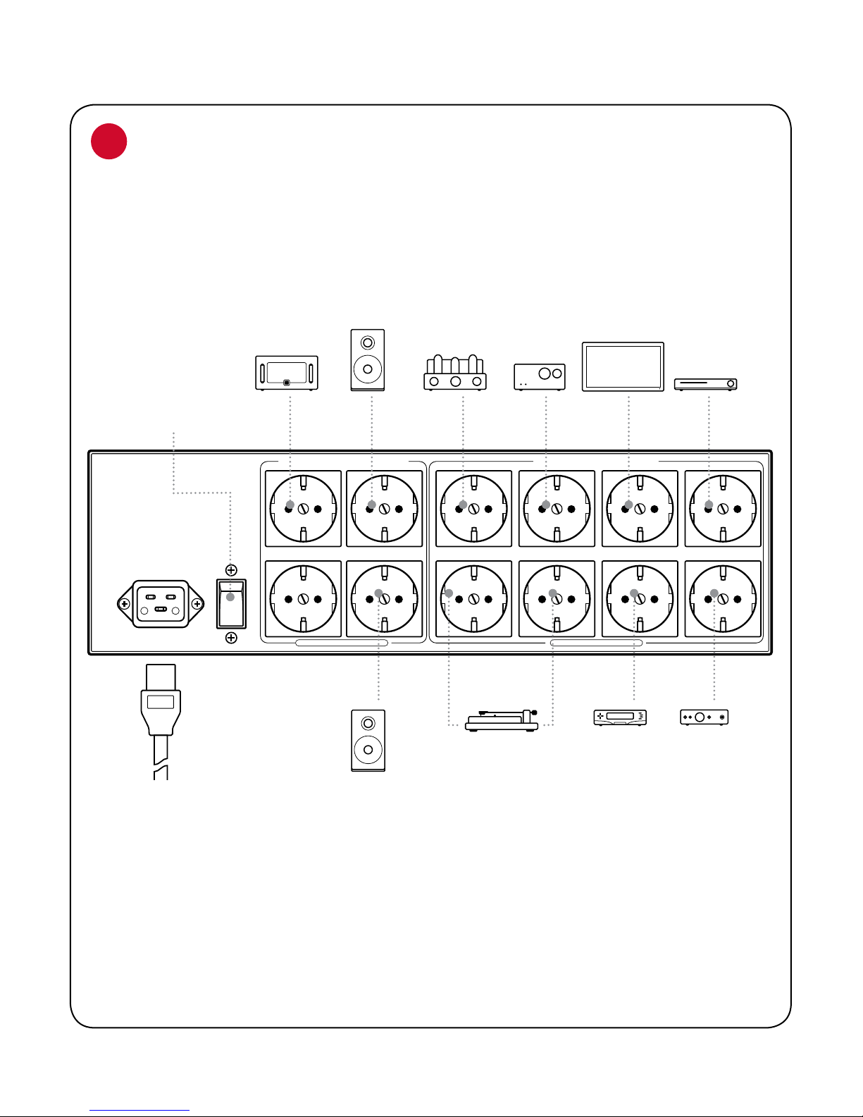
High Current/Low-Z Power Banks
There is one High Current/Low-Z Power banks (labeled AC outlets“1”through“4”).The outlets feature our Transient
Power Correction Technology, and are designed to enhance the performance of power ampliers via our circuit’s
low-impedance transient current reservoir. Power ampliers, mono-block ampliers, integrated ampliers,
powered receivers, or powered subwoofers should be connected to these four outlets. The primary mono, stereo,
or multi-channel power amplier(s) should be connected to AC outlet number 1. This enables the standby sense
circuit, which requires the current draw of a power amplier connected to (and only to) outlet number 1. In terms
of sonic performance, there is no dierence between outlets 1 through 4. If the standby sense circuit is not utilized,
and the sense circuit bypass switch is set to “Enabled,” any of the four high current outlets may be utilized.
For systems with only one or two power ampliers, the two uppermost outlets of the high current banks will
provide slightly superior performance due to their closer proximity to the AC outlets’ radio frequency noise-
dissipation circuit. However, the outlets located directly below will certainly aord exemplary performance!
Regardless of class of operation or circuit topology (valve, solid-state, digital, or otherwise), the Transient Power
Correction Circuit will not compress the current of any power amplier. Quite to the contrary, it will improve the
amplier’s performance by supplying the low-impedance current source that the amplier’s power supply so
desperately needs.
However, the other eight AC outlets (Ultra-Linear Noise-Dissipation System) are not appropriate for power
ampliers. They have been optimized for line-level audio preampliers, DACs, universal players, turntables, and
video products that utilize constant current voltage amplier circuits. These circuits never suer from current
compression, but their lower input level and higher gain require a more robust means of noise dissipation. This
is key to the Niagara 5000EU’s discrete AC power banks, in that not every circuit is treated the same, but rather
isolated bank by bank and optimized for best performance.
Ultra-Linear Noise-Dissipation System Power Banks
Ultra-Linear Noise-Dissipation System Power Banks
There are two banks that utilize this technology within the Niagara 5000EU. Both of these are in turn isolated from the
High-Current/Low-Z bank (outlets 1 through 4). This oers a great advantage in controlling the complex interactions
of RF (radio frequency) and other induced noises present in the AC power supplied from your utility, the noise that
will be present on and in every AC cord, and the noise that is produced within your system’s components and that
“backwashes”into the Niagara 5000EU’s output circuits.
Though it would be simple to recommend putting the digital or video components into bank 2, and the line-level audio
components and turntables into banks 3, the quest for optimal performance is more complex. This scenario will work,
and likely work well, but a certain amount of experimentation is best given the fact that no lter can eliminate 100% of
all noise, the size of many of these RF-induced waveforms is as small as the edge of this paper you’re reading, and the
interactions are complex. So long as the power ampliers are in their appropriate bank (outlets 1 through 4), and the
other components are in bank 2 (outlet 5 through 8) or bank 3 (outlets 9 through 12), you should experience exemplary
performance. Still, for the audiophile with patience, the reward will be system performance with the highest possible
resolution and lowest possible noise.