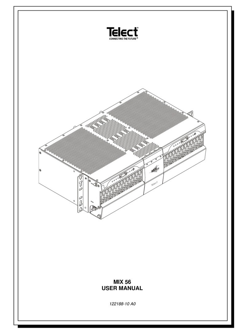
Beijing Huahuan Electronics H9MO-1641S User manual

H9MO-1641S
STM-1 MSTP
User Guide
Beijing Huahuan Electronics Co., Ltd.
2005.2

BEIJING HUAHUAN ELECTRONICS Co., LTD.
H9MO-1641S User Guide V2.2
- P. ii -
Disclaimer
The information contained in this document is subject to change without
notice and does not represent a commitment on the part of Beijing Huahuan
Electronics Co., Ltd. (Huahuan). The information in this document is believed to
be accurate and reliable, however, Huahuan assumes no responsibility or liability
for any errors or inaccuracies that may appear in the document.
Copyright©2005 by Beijing Huahuan Electronics Co., Ltd. All rights reserved. No part of
this publication may be reproduced or distributed in any form or by any means, without prior
written permission of Huahuan.
Product Model: H9MO-1641S
Product Name: STM-1 MSTP
Manual Version: 2.2 (English)
Last Update: 2005. 2
BEIJING HUAHUAN ELECTRONICS Co.,LTD.
Address: No.26, Shangdi 6th Street,
Haidian District, Beijing, 100085
P.R. China
Tel: (8610)62981998, (8610)62988820, (8610)62960985
Fax: (8610)82899800
Web: http://www.huahuan.com;http://www.huahuan.com.cn
E-mail:support@huahuan.com;support@huahuan.com.cn

BEIJING HUAHUAN ELECTRONICS Co., LTD.
H9MO-1641S User Guide V2.2
- P. iii -
Table of Contents
1GENERAL ................................................................. 1
2EQUIPMENT NETWORKING TOPOLOGY....................... 2
2.1 RING NETWORK ................................................................... 2
2.2 CHAIN NETWORK.................................................................. 3
2.3 BRANCH NETWORK .............................................................. 3
2.4 MESH NETWORK .................................................................. 4
3SYSTEM COMPOSITION ............................................. 4
3.1 EQUIPMENT CONFIGURATION ................................................ 4
3.2 FRONT PANEL...................................................................... 6
3.2.1 INDICATORS ........................................................................... 6
3.2.2 ETHERNET INTERFACE ............................................................. 7
3.2.3 OPTICAL INTERFACE ................................................................ 8
3.2.4 SERVICE PHONE INTERFACE ..................................................... 8
3.2.5 LCD DISPLAY......................................................................... 8
3.3 REAR PANEL ..................................................................... 10
3.3.1 E1 INTERFACES ADAPTOR BOARD............................................ 10
3.3.2 SYSTEM CLOCK INTERFACE .................................................... 11
3.3.3 MONITOR PORT (SV) INTERFACE ............................................. 11
3.3.4 DATA PORT INTERFACE .......................................................... 12
3.3.5 ALARM OUTPUT CONNECTOR.................................................. 12
3.3.6 GROUNDING CONNECTOR ...................................................... 12
3.3.7 POWER ON/OFF SWITCH AND RECEPTACLE ............................. 12

BEIJING HUAHUAN ELECTRONICS Co., LTD.
H9MO-1641S User Guide V2.2
- P. iv -
4EQUIPMENT INSTALLATION ...................................... 13
4.1 GENERAL .......................................................................... 13
4.2 INSTALLATION .................................................................... 13
5SYSTEM CONFIGURATION........................................ 14
5.1 OLT-A INTERFACE ............................................................. 15
5.2 OLT-B INTERFACE ............................................................. 20
5.3 OLT-C INTERFACE ............................................................. 21
5.4 ETHERNET INTERFACE........................................................ 21
6SYSTEM SPECIFICATIONS........................................ 23
6.1 STANDARD COMPLIANT ....................................................... 23
6.2 BASIC CHARACTERISTIC...................................................... 23
6.3 OPTICAL INTERFACE SPECIFICATIONS ................................... 23
6.4 2MBPS INTERFACE ELECTRICAL CHARACTERISTICS ............... 23
6.5 ETHERNET DATA INTERFACE CHARACTERISTICS..................... 24
6.6 EXTERNAL SYNCHRONIZATION ............................................. 24
6.7 MANAGEMENT INTERFACE................................................... 24
6.8 SYSTEM POWER SUPPLY ..................................................... 24
6.9 WORKING ENVIRONMENT .................................................... 24
6.10 DIMENSIONS...................................................................... 24
6.11 WEIGHT ............................................................................ 24

BEIJING HUAHUAN ELECTRONICS Co., LTD.
H9MO-1641S User Guide V2.2
- P. 1-
1
General
The H9MO-1641S is a classic STM-1 SDH fiber optic Multiplexer (at a transmission rate of
155.520Mbit/s), mainly designed for access networks and various dedicated networks. With
state-of-art compact design, it is a new generation of MSTP (Multi-Service Transport Platform) for
optic network transport and access.
The H9MO-1641S can be configured as terminal multiplexing (TM) equipment, add/drop
multiplexing (ADM) equipment or relay equipment, and is suitable to for optical transmission
networks such as chain networks and dedicated protection rings. The H9MO-1641S provides an
optional 3 optical directions; and total of 16 transparent channels for digital transmission at
2048kbit/s (E1) between nodes. Furthermore, the equipment can also provide fast Ethernet and
other data service access and transmission; for use in telecommunication services and wideband
data applications.
H9MO-1641S can synchronize with external clocks, line clocks or internal high precision oscillating
sources. It supports two input clocks (2Mbit/s or 2MHz) and one output clock (2Mbit/s or 2MHz). The
system clock processing circuit is based on self-developed algorithm and realization chips, greatly
increasing the synchronization characteristics of SDH networks, offering a timing guarantee for
configuring multi-node networks with complicated topological structures. Special technical provisions
have been adopted in the equipment to suppress LF jittering in the E1 channel, with parameters that
exceed the requirements in the latest ITU-T G.823 recommendation.
H9MO-1641S integrates the data service access, exchange and transmission, and has greatly
raised the transmission efficiency by means of the statistical multiplexing feature for data services. It
also adopts the most advanced MPLS labeling technology, to classify data services, provide differential
service quality for different customers, thus increasing the exchange efficiency, enhancing the system
stability and offering full management control for customers. The system is also provided with a service
telephone subsystem, enabling hotline, point-to-point or point-to-multipoint dialing for voice
communication that especially useful for system provisioning.
The network system designed with the H9MO-1641S multiplexer can be managed by our SNMP
supervision software (H7GMSW). The network operation conditions can be monitored in real time via
the supervision system, to control the loop back testing, manage channel resources and general
network management. The main control console of the supervision system is based on a Windows
environment with the usual visual user interfaces, featuring simple operation and ease of use. The
dedicated interface adopts a TABS protocol, and is connected with the main control console via RS485
bus. A portable supervision computer can be connected via an RS232 interface.

BEIJING HUAHUAN ELECTRONICS Co., LTD.
H9MO-1641S User Guide V2.2
- P. 2-
The H9MO-1641S multiplexer is a compact design with 1U height, supplied with either DC±48V or
AC220V power supply, and suitable for inclusion in 19” racks. It is also suitable for desktop mounting
with 4 optional feet which can be supplied with this compact unit.
2
Equipment Networking Topology
The H9MO-1641S multiplexer can form ring, chain, point-to-point, and point-to-multipoint
transmission networks; or to form more complicated networks in conjunction with other H9MO
members. These paragraphs describe the modes and features to realise the various network
connections with this equipment.
2.1 Ring network
Figure 2.1 Schematic diagram of a ring network formed by H9MO-1641S multiplexers.
AB
Main Node
A
B
B
B
A
A
C
Figure 2.1 Ring network
All devices in figure 2.1 are of the relay type. The “A” and “B” marked on both sides of devices
represents respectively the ‘Optical Port A’ and ‘Optical Port B’ of the device, irrespective of actual
transmission direction. The connection lines between the devices are optical cables and the arrows
indicate signal directions. Please note the relations of transmission directions with the input and output
optical modules on “A” and “B” optical terminal boards, and they must be connected correctly. The
SNMP management system can be connected with device at any node.
The ring network formed by the equipment has a self-healing capability. In the case of fibre break at
any position during operation, the supervision system will automatically perform a switchover for the
multiplexing section, to restore normal communication between all nodes on the ring network quickly.

BEIJING HUAHUAN ELECTRONICS Co., LTD.
H9MO-1641S User Guide V2.2
- P. 3-
In case of failure of a node on the ring (such as loss of power supply), that node will be
automatically excluded from the network without affecting communication between other nodes of the
network.
To maintain stable operation of the network, the self-healing operation is shielded within a number
of minutes after turning on. Furthermore, it will not restore immediately when the conditions initialising
the self-healing has disappeared, and there is a protection period of 3~12 min., during which the
self-healing condition will remain. The protection period can be cancelled using the SNMP
management software.
2.2 Chain Network
A chain transmission network as shown in Figure 2.2 can be formed using the H9MO-1641S
multiplexer.
BAAA
Figure 2.2 Chain network
In figure 2.2, both the home and terminal equipment are terminal equipment, and the remaining
multiplexer is of relay type. “A” and “B” represents ‘Optical port A’ and ‘Optical port B’ of the device,
irrespective of the actual transmission direction. Two terminal devices can also form a point-to-point
connection. Please note the relationship between the home and terminal devices with the “A” and “B”
directions of the relay device. The master control console computer can be connected to any node
device on the chain network
2.3 Branch Network
A branching network as shown in Figure 2.3 can be formed by using the H9MO-1641S multiplexer.
C
AB
AA
Figure 2.3 Branch network
By using the 3rd (optional) optical interface, the transmission path can be branched by using optical
port C of the interim H9MO-1641S to form a ‘T’ shape network in between any chain network. The

BEIJING HUAHUAN ELECTRONICS Co., LTD.
H9MO-1641S User Guide V2.2
- P. 4-
master control console computer can be connected to any node device on the branch network, not
necessarily connected to the home terminal device.
2.4 Mesh network
Figure 2.4 shows a more complicated network formed by using the H9MO-1641S multiplexer in
conjunction with other multiplexers in our range.
H9MO-1641X
H9MO-155
H9MO-155
H9MO-1641S
H9MO-1641S
H9MO-1641S
H9MO-1641S
H9MO-1641S
H9MO-1641S
H9MO-155 H9MO-1641S
H9MO-155
Figure 2.4 Mesh network
In this figure, the H9MO-1641S can be configured as a terminal, branching and cross connect
multiplexer. It supports a number of optical terminal boards and sub-network protection of channels.
The multiplexer can be formed into various network topological structures to suit the application or
network topology requirements. The H9MO-155 and H9MO-1641S equipment in the network shown in
Figure 2.4 are all of relay type except the terminal station device. The “east” and “west” marked on both
sides of equipment represents the OHT/OLT boards on the east and west, irrespective of their actual
directions.
The master management computer can be connected to the H9MO-1641X equipment at any
node.
3
System Composition
3.1 Equipment Configuration
Main functional units of H9MO-1641S:
System main board, includes OLT-A (Optic ‘A’ port)
OLT-B (Optical Port ‘B’ optional)
OLT-C (Optical Port ‘C’ optional)
E1 interface (embedded 16 ports)

BEIJING HUAHUAN ELECTRONICS Co., LTD.
H9MO-1641S User Guide V2.2
- P. 5-
ETH Ethernet board (optional)
PWR power supply board (AC or DC)
Case (including master board)
Equipment configuration type:
Depending upon the application required the H9MO-1641S can be configured as a branch, relay or
terminal multiplexer. In relay mode it can be used in a chain network or self protecting ring mode. In
terminal mode it may be used as a terminal device in a chain network (including point to point). In
terminal mode it can be a home type (H) or terminal type (T). The 3rd optic board can be used to extend
the network into a branch mode.
The difference between a terminal device and a relay device is that the terminal device is only
equipped with one OLT board, while a relay device needs two. By adding one OLT board, a terminal
device can be turned into a relay device. This network structure is suitable for phased construction and
extension of networks.
The H9MO-1641S supports Ethernet by adding the optional ETH board.
The AC or DC power supply is customer defined at order.
Board position arrangement:
H9MO-1641S multiplexer is optimized for 19” wide chassis mount, and the positions of various
functional elements are as shown in Figure 3.1. The OLT-A is situated on the mother board and the
optional OLT-B, OLT-C and ETH boards are shown.
SV
AMP
RJ45
RJ11 LED
H9MOS.STM-1.SYS
Front
DATA
ABCETH
CNM27CNM12
x16
CNM11
CNM10
CNM9
..........
CNM3
CNM4
CNM2
CNM1
CNM6
CNM5
CNM7
LCD
Tx Rx
Tx Rx
Tx Rx
UP
DOWN
LEFT RIGHT
Figure 3.1 H9MO-1641S PCB internal layout

BEIJING HUAHUAN ELECTRONICS Co., LTD.
H9MO-1641S User Guide V2.2
- P. 6-
3.2 Front Panel
The front panel of the H9MO-1641S includes an RJ11 connector for order wire (PHONE), SC
connectors (OLT-A, OLT-B, OLT-C), Ethernet connector and system status indicators.
The H9MO-1641S is 1U height with 19” standard rack mounting as shown in figure 3.2.
H9MO-1641S
Hua
h
uan
PHONE
ALMP
PWR ALMD SYS
FDX Link/Act
Rx Tx
CRx Tx
B
RxTx A
Etherent
华环
H9MO-1641S
Figure 3.2 H9MO-1641S front panel
3.2.1 Indicators
There is a total of 6 LEDs located on the left and right of the front panel for a fully equipped
H9MO-1641S.
LED Color Description
PWR Green Lit – Power normal
ALMP Red Lit – Major alarm
ALMD Yellow Lit – Minor alarm
SYS Green Flashing – System function normal
FDX Green Flashing – Data transmit and receive
Link/Act Green Lit – Link active
Table 3.1 LED description
When the H9MO-1641S is in boot up mode or software upgrade mode, the indicators ‘ALMP’;
‘ALMD’ and ‘SYS’ have a special meaning for the system status.
(1) Power Up, ‘ALMP’ Red lit up (Last for around 6 – 10 Seconds)
(2) ‘SYS’ Green lit up (last for around 5
seconds)
(5) ‘ALMD’ Yellow lit up
(3) Three LEDs ‘ALMP’, ‘ALMD’, ‘SYS’
flashing in registry counting mode
(6) Three LEDs ‘ALMP’, ‘ALMD’ and
“SYS’ flashing simultaneously.
(4) ‘SYS’ flashing Green, SV program in
normal operation.

BEIJING HUAHUAN ELECTRONICS Co., LTD.
H9MO-1641S User Guide V2.2
- P. 7-
Table 3.2 LEDs indicator sequence
Stage (1), verify the SV program with program length and checksum, then go to stage (2). If
the system is in upgrade mode, stage (5) will appear. Stage (2) indicates the transfer of SV
program and uploading to the FPGA during stage (3). When into stage (4), the system is under
normal operating conditions and indicates that equipment is operating normally. The ‘ALMP’ and
‘ALMD’ may be light up depending on the status of the system.
Stage (5) and (6) indicates that the system is under Boot ROM mode which is used for
upgrading the operating software. The software upgrade is controlled by the SNMP management
system H7-GMSW. When the unit is under control and in upload mode, all 3 LEDs ‘ALMP’, ‘ALMD’
and “SYS’ will flash simultaneously. When the code is downloading, all 3 LEDs will flash ,once the
download has completed the 3 LEDs will flash simultaneously once again.
3.2.2 Ethernet Interface
H9MO-1641S is equipped with an Ethernet interface connector (Ethernet module is an option)
by using standard MDI-II RJ45 socket. Signal pin definition is shown in figure3.3.
Figure 3.3 Ethernet connector pin definition
For the RJ45 connector, the pin numbering and pin assignment is shown in figure 3.4.
Fig 3.4 Pin numbering of the RJ45 plug
Pin Number 1 2 3 4 5 6 7 8
Definition RxD+ RxD- TxD+ TxD-
Table 3.3 RJ45 plug pin definition
(Hint: The 100Base-TX interface of this device is a standard MDI-X interface. For
connecting to an MDI device, such as an Ethernet LAN card, a straight through cable is used. For
connecting to MDI-X equipment, such as a hub or switch, a cross-over cable is required.)
TPON
TPOP
TPIP
TPIN
8
1

BEIJING HUAHUAN ELECTRONICS Co., LTD.
H9MO-1641S User Guide V2.2
- P. 8-
3.2.3 Optical Interface
The H9MO-1641S uses a high reliability optical transceiver device with SC connector. It is
equipped with 3 sets of optical connectors (labeled A, B and C) and ‘Tx’ for the optical signal
output and ‘Rx’ for optical signal input. The OLT-A has a built-in interface, whilst the OLT-B and
OLT-C modules are an option depending upon the application.
There is a notch on the SC connector to ensure positive cable latching. The notch of the
OLT-A is on the top and OLT-B and OLT-C is on the bottom. Ensure that the fiber cable is inserted
correctly and that the transmit and receive end of the cable is connected correctly.
(Hint: The curvature of the cable must be at least 50 mm or more. When no cable is
inserted to the optical socket, a cover must be used.)
(Caution: Do not look at the laser connector directly. The laser may damage the eye
permanently.)
3.2.4 Service Phone Interface
The H9MO-1641S provides an RJ11 connector for the service phone line (order wire) via
the E1 overhead bit in the STM-1 frame structure. The order wire phone provides service
contact between the nodes on the network, it also functions as an input panel for the control of
the LCD display, details of which are in the next section.
The order wire can be set in hotline or dial mode via management software or through
the F interface (RS232-SV interface). In hotline mode, when any node hooks off, all nodes set
in hotline mode will ring; when it is set as dial call, the phone sets must operate in dual-tone
multi-frequency (DTMF) mode, to receive selective calls from point to point, a point to multiple
points, point to group and point to whole line.
3.2.5 LCD Display
For convenience of operation, the H9MO-1641S is provided with an LCD display which
indicates system status, clocking status, alarm message and alarm messages.
By using the order wire phone set you can access the LCD display and choose the various
options as detailed below.

BEIJING HUAHUAN ELECTRONICS Co., LTD.
H9MO-1641S User Guide V2.2
- P. 9-
﹡0
﹡3
ClkInfo
Free Shock
Lock
Keep
FrameInfo
ADM
TM
OltMode
1 OltCard
2 OltCards
3 OltCards
OltPrInfo
PC
PB
PA
﹡0
﹡
1
﹡2
﹡
3
﹡
4
OltAlarm
LOSA
LOSB
LOSC
ClkAlarm
ExALoss、ExBLoss
ExAB、ExBB
LALoss,LBLoss,LCLoss
LABad、LBBad、LCBad
E1 RDI
0 ~15
E1 AIS
E1 LOS
E1 LOP
﹡0
Main Menu
*1 LocalInfo
*2 StateInfo
*3 AlarmInfo
StateInfo
*1 ClkInfo
*2 FrameInfo
*3 OltMode
*4 OltPrInfo
AlarmInfo
*1 OltAlarm
*2 ClkAlarm
*3 E1RDI
*4 E1AIS
*5 E1LOS
*6 E1LOP
0 ~15
0 ~15
0 ~15
*4 MaskCtrl
﹡1﹡0
﹡1
﹡2
﹡3
﹡4
﹡5
﹡6
MaskCtrl
*1 SetMask
*2 ClrMask
﹡4﹡0
﹡
2
﹡
0
Huahuan
H9MO-1641S
On
Hook Off
Hook
IP:(IP Addr)
485BR:(485 Baud Rate)
Tel:(Phone number)
VerS:(Software Version)
LocalInfo
VerE:(Ethernet Version)
Figure 3.5 Command flowchart and message display on LCD
LCD display Acronyms
Acronym Description
TM Terminal mode
ADM Add-drop mode
PA Protect OLT-A

BEIJING HUAHUAN ELECTRONICS Co., LTD.
H9MO-1641S User Guide V2.2
- P. 10 -
PB Protect OLT-B
PC Protect OLT-C
OLT Optic light terminal
LOM Loss of frame on optical port
LOSA Loss of signal on OLT-A
LOSB Loss of signal on OLT-B
LOSC Loss of signal on OLT-C
ExALoss External clock A signal loss
ExBLoss External clock B signal loss
ExAB Bad external clock A
ExBB Bad external clock B
LALoss Line clock A signal loss
LBLoss Line clock B signal loss
LCLoss Line clock C signal loss
LABad Bad line clock A
LBBad Bad line clock B
LCBad Bad line clock C
RDI Remote failure detected indication
LOP TU-12 pointer loss
AIS Alarm indication for E1 port (all “1” received)
LOS Loss of signal on E1 port
VerS Software version
VerE Ethernet module version
485BR RS485 port baud rate
Table 3.4 Acronym of LCD display
3.3 Rear Panel
The rear panel of the H9MO-1641S is shown in figure 3.6.
1
0
ON
OFF
220V /50Hz
A
C
ALM
E1 Termination block
SV
DATA
Figure 3.6 H9MO-1641S rear panel
3.3.1 E1 Interfaces Adaptor Board
An AMP connector is used on the rear panel of the H9MO-1641S for the E1 interface. An
alternative adaptor board is shown in figure 3.7 and used to provide 75 ohm or 120 ohm interfaces.

BEIJING HUAHUAN ELECTRONICS Co., LTD.
H9MO-1641S User Guide V2.2
- P. 11 -
1 2 3 4 5 6 7 8
IN
OU
T
9 10 11 1213 1415 16
DATA
CLK1 CLK2
OUT
E1ADP-75
E1_a
E1_b
GND
120OWire Wrap Connector
75OCoaxial Connector
Figure 3.7 E1 adaptor board
On the main circuit board, there are 16 jumpers (CNM12 ~ CNM27) for 75 ohm or 120 ohm
E1 interfaces. The 75 or 120 connectors are clearly marked on the circuit board. By default the unit
is set to 75 ohm. Changing the setting will invalidate the warranty
(Hint: ‘CC4(1.0/2.3) ’ type coaxial connector is used for the 75 ohm E1 interface. This
connector is auto-locked when cable is plugged in. Push down the connector head to release the
lock before unplugging the cable, otherwise damage may result.)
3.3.2 System Clock Interface
The clock connectors are located on the E1 Adaptor Board. It includes two external input
clock connectors (labeled as ‘CLK1’ and ‘CLK2’) and one output clock connector (labeled as
‘OUT’).
The input or output clock uses the 2048 KHz or 2048 Kbit/s synchronous clock, and the
impedance is 75 ohm (coaxial) or 120 ohm (wire wrap). The clock mode and impedance is defined
on the main circuit board as below.
Terminal Impedance Jumper Position
75 ohm Up
CLK1 120 ohm CNM 10 Down
75 ohm Up
CLK2 120 ohm CNM 9 Down
Table 3.5 Jumper selections for CLK1 and CLK2
Operation Mode Impedance Selection
Jumper 2Mbit/s 2MHz Jumper 75 ohm 120 ohm
CNM 6
CNM 5 Left Right CNM 7 Left Right
Table 3.6 Jumper selections for output clock
3.3.3 Monitor Port (SV) Interface
The DB9 connector on the rear panel is an RS232 (F-interface) for terminal access and
RS485 for the SNMP management system. The terminal can access the F-interface (RS232) for
changing the physical address. The default baud rate is set to 9600 bps. The system can be
controlled and managed from the RS485 port. Default baud rate for the RS485 is 19200 bps (User
definable rates are 1200, 1800, 4800, 9600, 19200 and 38400 bps).

BEIJING HUAHUAN ELECTRONICS Co., LTD.
H9MO-1641S User Guide V2.2
- P. 12 -
The jumpers CNM 1 and CNM 2 are used for the RS485 bus termination. When the unit is
defined as a terminal device, the jumpers must put on the left hand side, otherwise, put them on
the right hand side.
RS232 RS485
Pin Number 1 2 3 4 5 6 7 8 9
Definition Rx Tx Gnd Rx- Rx+ Tx- Tx+
Table 3.7 DB9 (SV port) pin assignment
3.3.4 Data Port Interface
The H9MO-1641S supports one transparent asynchronous data port with fixed rate of 9600
bps. This data port can be used for low speed data communication or remote monitoring. The pin
assignment is the same as the SV port and shown as table 3.7.
3.3.5 Alarm Output Connector
The wire wrap pin alarm connector is used for external audible (bell) or visible (light) alarms.
These conditions are defined by inputting the required outputs into the management system.
When using the rack alarm controller for power and alarm monitoring, plug in the accessory
cable which comes with the controller as shown in figure 3.8. The alarm controller supports both
audible and visible alarms simultaneously.
Figure 3.8 Alarm connector
3.3.6 Grounding Connector
For the safety of operating personnel, the equipment must be earthed. A screw type
grounding point is located on the rear panel of the H9MO-1641S.
3.3.7 Power ON/OFF Switch and Receptacle
The power supply can be either AC 220V or DC -48V. For DC supply, connect the supply as
shown on the panel. When AC supply is used, plug in the power cable to the receptacle which
equipped with 1A fuse.
(Caution: The AC supply must be earthed for safe operation.)

BEIJING HUAHUAN ELECTRONICS Co., LTD.
H9MO-1641S User Guide V2.2
- P. 13 -
4
Equipment Installation
4.1 General
H9MO-1641S multiplexer is a 1U high, 19” rack mounted unit which can be mounted in 2m or 2.6m
19” equipment frames. Power supply monitoring alarms can be configured, to provide audio and visual
alarms.
It also has 4 pads (10mm height) to enable use as a desktop device.
H9MO-1641S physical dimensions are shown as figure 4.1.
465mm
31.8 mm
440 mm
44 mm
245 mm
H9MO-1641S A
Hua
h
uan
BC
Figure 4.1 H9MO-1641S physical dimensions
4.2 Installation
To ensure correct installation and functioning of the H9MO-1641S multiplexer you should take note
of the following recommendations:-
1. Ensure that you have all the corresponding parts and optional modules that are required for
your application.
2. Ensure that you connect all cabling in accordance with the manufactures instructions.
3. Do not attempt to change any change internal settings or tunable components on the mother
board. Any attempt to do so will invalidate the warranty and affect the performance of the
product
4. Avoid the damage of the fibre and connector by removing slowly with minimum use of force
5. After removal always cover with a protective cap to avoid dust and abrasion which will affect
the transmission properties..
6. Never look at the optical connector directly. The laser beam from the connector may damage

BEIJING HUAHUAN ELECTRONICS Co., LTD.
H9MO-1641S User Guide V2.2
- P. 14 -
the eye permanently.
7. The unit should be installed inside a room or building which maintains the equipment within the
manufacturers environmental specifications.
5
System Configuration
The H9MO-1641S is managed by the H7-GMSW SNMP management software. For detailed
operation instructions for the H7-GMSW management software, please refer to the H7-GMSW user
guide. The following description is related to the operation of the H9MO-1641S multiplexer only.
The RS485 of the SV console port is used for management access. The F-interface (RS232) is
used to set the IP address of the unit by using the “setaddr” command.
Refer to the H7-GMSW management software guide to add a new device of the system; the
equipment icon will be displayed as shown in figure 5.1. The three optical buttons from left to right,
represents the OLT-C (C), OLT-B (B) and OLT-A (A) interface. Note that the OLT-B and OLT-C
interfaces are optional and may not have function depending upon the actual system configuration.
Figure 5.1 H9MO-1641S icon optical ports
Double click the empty space on right side of the OLT-A, a system message will pop up as figure
5.2. The pop-up window is used to change the system soft address, but the system hard address may
be changed by using the F-interface (RS232).
Figure 5.2 H9MO-1641S system soft address
The software will present different interface windows by double clicking the OLT-A, OLT-B, OLT-C
or the Ethernet port.

BEIJING HUAHUAN ELECTRONICS Co., LTD.
H9MO-1641S User Guide V2.2
- P. 15 -
5.1 OLT-A Interface
Double click the OLT-A, the pop-up window is shown as figure 5.3.
Figure 5.3 OLT-A interface
From the pop-up window of the OLT-A, that is used for status display and defining the ‘Alarm
Indicator’; ‘Loopback’; ‘SDH Clock Mode’; ‘Operation Mode’; ‘J0 Byte Setup’; ‘J1 Byte Setup’; ‘J2 Byte
Setup’; ‘Version Query’; ‘RS485 Rate Setting’; ‘E1 Signal Status’ and ‘Self Healing Mode’. The
‘Loopback’ command is used for interface OLT-A only.
Click the ‘SDH Clock Mode’, the ‘System Clock Setting’ will appear as figure 5.4. The upper
portion is used to define the priority of the external clock (including the line clock). The highest priority is
‘I’ and the lowest is ‘V’.
On the left hand side of the lower portion, it shows the clock mode which is currently in use. ‘Free
Oscillation’ means at tthe internal crystal clock is being used. When the external clock is selected, the

BEIJING HUAHUAN ELECTRONICS Co., LTD.
H9MO-1641S User Guide V2.2
- P. 16 -
priority clock will be shown. In the middle of the lower portion, it defines the clock mode of the external
input and output clock (line clock is not included). On the right, you can select the internal or external
clock as the system clock.
Figure 5.4 System clock setting
When clicking on the ‘Operation Mode’, the window for the operation mode of OLT-A is shown as
shown in figure 5.5. The upper part defines the optical interface protection. The middle and lower part
defines the optical path and system operation mode. Depending on the number of optical interfaces
you can define the optical path as single; dual or tri-path. When the internal clock is used,’ Terminal’
mode should be used. When ‘ADM’ mode is used the external clock setting should be selected. The
‘Query’ button is used to check the current status of the system.
Table of contents
Other Beijing Huahuan Electronics Multiplexer manuals
