Beko E1 CHASSIS User manual

Service Manual
E1 CHASSIS

1
CONTENTS PAGE
oSafetyInstructions 2
oTechnical Specifications 3
oRemote Control 4
oPreperations 5
oOperatingYourTV 6
oBlockDiagram 10
oICSpecs 11
oPin Voltages of IC’s 18
oOSCILLOSGRAPHS OF SOME IC PINS 19
oElectrical Adjustments 22
oChannel Frequency Tables 25
oSparePartList 27

2
1. SAFETY INSTRUCTIONS .
GENERAL GUIDELINES
1. It is advised to insert an isolation transformer
in the AC supply before servicing a hot
chassis.
2. Potentials as high as 33KV are present when
this receiver is in operation. Operation of the
receiver without the rear cover involves the
danger of a shock hazard from the receiver
power supply. Servicing should not be
attempted by any one who is not competent
with the precautions necessary when working
on the high voltage equipment. Always
discharge the anode of the tube.
3. When servicing observe the original lead
dress in the high voltage circuits. If a short
circuit is found, replace all the parts which
have been overheated or damaged by the
short circuit.
4. Always use the manufacturer’s replacement
safety components. The critical safety
components marked with on the
schematics diagrams should not be replaced
by other substitutes. Other substitute may
create the electrical shock, fire or other
hazards. Take attention to replace the
spacers with the originals. Furthermore where
a short circuit has occurred, replace those
components that indicate evidence of
overheating.
5. After servicing, see that all the protective
devices such as insulation barriers, insulation
papers, shields and isolation R-C
combinations are correctly installed.
6. When the receiver is not being used for a
long time of period of time, unplug the
power cord from the AC outlet.
7. After servicing make the following leakage
current checks to prevent the customer from
being exposed to shock hazard.
LEAKAGE CURRENT COLD CHECK
1. Unplug the AC cord and connect a jumper
between the two prongs of the plug.
2. Turn the receiver’s power switch on.
3. Measure the resistance value with an
ohmmeter, between the jumpered AC plug
and each exposed metallic cabinet part on
the receiver, such as screw heads, aerials,
connectors, control shafts etc. When the
exposed metallic part a return path to the
chassis the reading should be between
4Mohm and the 20Mohm. When the exposed
metal does not have a return path to the
chassis, the reading must be infinite.
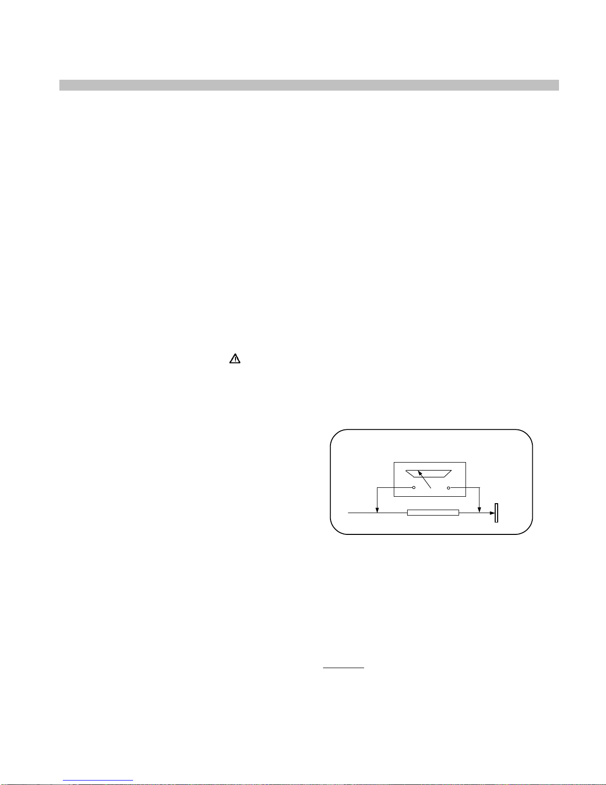
LEAKAGE CURRENT HOT CHECK
1. Plug the AC cord directly in to the AC outlet.
Do not use an isolation transformer for this
check.
2. Connect a 2Kohm 10W resistor in series with
an exposed metallic part on the receiver and
an earth, such as a water pipe.
3. Use an AC voltmeter with high impedance to
measure the potential across the resistor.
4. Check each exposed metallic part and
check the voltage at the each point.
5. Reverse the AC plug at the outlet and repeat
each of the above measurements.
6. The potential at the any point should not
exceed 1.4 Vrms. In case a measurement is
outside the limits specified, there is the
possibility of a shock hazard, and the receiver
should be repaired and rechecked before it
is returned to the customer.
HOT CHECK CIRCUIT AC-Voltmeter
TO INSTRUMENTS
EXPOSED
METALLIC PARTS Water pipe
(earth)
2 K Ohm
Figure 1
X-RAY RADIATION WARNING
The primary source of X-ray radiation in this receiver
is the picture tube. The chassis is specially
constructed to limit X-ray radiation. For continued X-
ray radiation protection, replace the tube with the
same type of the original one.
CAUTION
AFTER REMOVAL OF THE ANODE CAP, DISCHARGE THE
ANODE OF THE PICTURE TUBE AND THE ANODE CAP TO
THE METAL CHASSIS, CRT SHIELD, OR THE CARBON
PAINTED ON THE CRT WITH A HIGH VOLTAGE PROBE

3
AND MULTIMETER (SELECT VDC) AND THEN SHORT CIRCUIT DIRECTLY TO DISCHARGE COMPLETELY
2. TECHNICAL SPECIFICATIONS .
Power source: 220-240V AC, 50-60Hz
Power consumption (nom.) : 40 W 14”
50 W 20”, 21”
Standby power consumption : 4 W
Aerial impedance : 75Ohm, coaxial type
Receiving system 1: PAL BG
PAL SECAM BG
PAL SECAM BG DK
PAL I
Receiving channels: VHF BAND I CH2-4
VHF BAND III CH5-12
CABLE TV S1-41
UHF BAND CH21-69
Audio outputs : 2.0W RMS at %10 THD 14”
2.5W RMS at %10 THD 20”, 21”
High Voltage : 23 ± 0.5 KV 14”
25 ± 0.5 KV 20”, 21”
Focus voltage : %25.6 ± %38 of EHT
Grid 2 voltage : 0-1400 V
Heater voltage : 6.2 ± 0.2 Vrms
Video/Audio Terminals : AV1 IN Video : 1 Vpp,75 Ohm
Audio : 0.5 Vrms, >10 Kohm
RGB
AV1OUT Video : 1 Vpp, 75 Ohm
Audio : 0.5 Vrms, <1 Kohm
AV2 IN (RCA, optional) Video : 1 Vpp, 75 Ohm
Audio : 0.5 Vrms, >10 Kohm
Operating temperature : 0-45 Degrees
Safety : IEC 65 /BS P2N
X-Ray radiation : ACC. IEC 65/BS P2N
1: TV set is produced to receive “one” of these colour and sound systems.

4
3. REMOTECONTROL
1. MUTE button
2. Ten key program button
3. Two digit program button (-/--)
4. MENU button
5. Program up button
6. Volume decrease button
7. Return to selected programme button (SWAP)
8. Information button (i)
9. STAND-BY button
10. AV-TV selection button
11. OK button
12. Volume increase button
13. Program down button
14. 16:9 picture format button
15. Sleep timer button
16. Normalization button
For Teletext Function (Opt.)
1. Yellow fastext button
2. Blue fastext button
3. Teletext/TV select button
4. Enlarge button
5. UPDATE button
6. MIX button
7. Green fastext button
8. Red fastext button
9. STOP button
10. SUB-PAGE button
11. REVEAL button
Special features
•Automatic Programming
•100 Programme Memory
•Available for Cable Channels (A decoder may be
required)
•Manual Fine Tuning
•Skipping back to the last channel you have
started to zapp via only one button(SWAP).
•16:9 picture format
•Scart Socket: Video cassette recorder, satellite
receiver, video disc player, DVD, TV games or a
home computer can be connected to this AV
socket with an appropriate connecting cable.
•Normalization system to recall the setting in
memory after the colour, contrast, brightness
setting have been changed.
•Automatic Volume Limiting.
•Infrared Remote Control.
•Your TV will automatically switch off if it’s been
programmed from 15 to 120 minutes.
•Automatically switch to Stand by five minutes
after a channel ceases to transmit.
•Multi language menu system
•Naming the channels (Automatic with ATS).
•NTSC playback.
•S-VHS via Scart.
•ATS: Automatic Tuning System with country
selection (*).
•Audio/Video RCA sockets (*).
•Headphone socket (*).
•Teletext reception (*).
•Zapping (*).
•I.P.S.: Intelligent Programme Switch: You can set
your TV to skip to a specific
•Channel at a specific time. It works also as an
alarm function (*).
•Childlock (*).
•Please Note: Zapping, I.P.S., Childlock are
optional if ATS exists.
(*): These features are not available in all models.

5
4. PREPARATIONS
MAIN SUPPLY CONNECTIONS
Connect the TV mains plug into your domestic mains
socket outlet (230 V 50Hz AC).
Press the Program up, Program down button or
Numeric Buttons on the remote handset to switch
the TV on.
AERIAL CONNECTION
Using a 75Ωaerial lead connect your TV to the
aerial outlet in your home.
BATTERY FITTING
Insert the 2 AAA Batteries supplied into the
compartment on the rear of the remote control,
ensure you follow the polarity diagram inside
the compartment.
PIN CONNECTIONS FOR SCART SOCKET
1-
Audio output Right 11- RGB input, Green
2- Audio input Right 12-
3- Audio output Left(Mono)13- Red ground
4- Audio ground 14- Ground
5- Blue ground 15- RGB input, Red
6- Audio input Left(Mono) 16- Blanking Signal
7- RGB input, Blue 17- Video output ground
8- Switching voltage 18- Video input ground
9- Green ground 19- Video output
10- 20- Video input
21-Screening
CONNECTING TV WITH VIDEO AND SATELLITE/DIGITALRECEIVER

6
5. OPERATING YOUR TV
A. ZAPP FUNCTİON (OPTİONAL)
Select the programme you would like to recall
by pressing SWAP button. Selected programme
number will appear on the upper left side of the
screen. Watching any
programme, you can recall the
selected one by pressing SWAP
button again. If you press SWAP
button again, you can recall the
last programme you
watched. You can cancel ZAPP function by
pressing INFO button.
B. SWAP FUNCTION
Allows you to swap between the program you
are watching and the
last selected program. i.e. If you
were watching Program 1 and
change to Program 11, press the
SWAP button to go back to
Program 1. Press it again to return to Program
11.
Note: If Zapping function is available SWAP
function will not work.
C. INFO
By pressing the “WHITE (i)” button the
programme number and programme
name (if it is exist) will appear on the
screen. This will disappear
automatically after a few seconds.
D. TUNING THE TELEVISION
There are two ways of tuning your television:
• Manual, where you control the tuning process
or Autoprogram where the television does it all
automatically.
• The TV sets equipped with ATS (Automatic
Tuning System) sorts the channels regarding
the broadcasting system of your country
(optionally).
Please Note
If the TV is set to a channel with no signal the
TV will return to standby after 5 minutes. The
time remaining is displayed on the screen.
Manual Tuning
Tuning the TV is accessed through the SETUP
menu.
To access the SETUP menu:
Press the MENU button twice. SETUP Menu
will appear.
a) If you don’t know the channel
number (Tuning with SEARCH
function).
Enter the SETUP menu by pressing MENU
button twice.
In the SETUP Menu select
PROGRAM NO and change to P1
using the Program down button to
select it and the Volume up or
Volume down button to change it.

7
Starting with Program P1, tune in the first
channel as follows:
Use the Program up button to select
SEARCH.Press the Volume up or
Volume down button to start the
tuning search. The search arrow will
appear. When the search finds a
strong searching. The picture will
appear, channel signal it will stop.
Identify which channel you are
watching (BBC 1, ITV 1 etc.) and decide which
program number you want it to be.
Use the Program down button to
select PROGRAM NO.
Use the Volume up/down buttons to
select the program number.
Use the Program down button to
select STORE. Press the OK button
and STORED will appear on the
STORE line.
You have now stored the first
channel.
Use the Program up button to select
again SEARCH and continue the
tuning procedure until you have
tuned in all the programmes you want or the
television can receive.
b) If you know the channel number. (Tuning
with channel numbers)
Press the OK button to select “S” for
cable channels and “C” for terrestrial
broadcast.
Use Volume up/down button to
select the channel number or enter
the channel number using the
Numeric buttons.
Use the Program down button to
select PROGRAM NO.
Enter the desired program number
by using the Ten key program
buttons
Use the Volume up/down buttons to
select the program number.
Use the Program down button to
select STORE. Press the OK button
and STORED will appear
on the STORE line. The channel will
be stored with the program number
you desired.
You have now stored the first
channel.
Use the Program up button to select
again CHANNEL and continue the
tuning procedure until you have
tuned in all the programmes you
want or the television can receive.
To exit the SETUP menu press the
TXT button.
Please note
The system will displayed automatically on
SYSTEM row i.e.BG, L, I, DK depending the
receiving broadcasting system of the country. In
some countries the broadcasting system can be
both in BG/DK or BG/LL´.Only the TV sets
produced with Pal Secam BG/DK or Pal Secam
BG/LL´ systems can receive both BG/DK or
BG/LL´ broadcasts.
Please note
If you do not press any buttons for 15 seconds
the TV will exit the menu system.
Automatic Tuning (Autoprogram)
Enter the SETUP menu as before.

8
Use the Program down button to
select AUTOPROGRAM and press
the OK button.
Please Note:
a) On the TV sets equipped with ATS a
COUNTRY SELECTION menu will appear.
Select the desired country using Program and
Volume buttons.
Press the OK button to select the country and
press the OK button again the Automatic Tuning
System regarding the broadcasting system in
the desired country.
b) On the TV sets without ATS pressing the OK
button starts AUTOPROGRAM.
When you are sure the aerial is
connected properly press the OK
button and to confirm it press OK
button again.
To cancel Autoprogram whilst it is
working press the Menu button. As
Autoprogram stores a channel it will
appear briefly on the screen.
Your TV is now tuned and ready to use
E. TV SET UP
The TV set up is accessed through a menu
system.
Once you have stored your set up, this is the
set up the TV will default to when you switch it
on.
Please note
If you do not press any buttons for 18-19
seconds the TV will exit the menu system.
There are three menus;
• Picture Menu
• Setup Menu
• Features Menu
• Picture Menu
To reach the picture menu press one time
to MENU button.
BRIGHTNESS
CONTRAST
COLOUR
SHARPNESS
To change, for example, the colour,
select it using Program down
buttons.
Use the Volume up and Volume
down buttons to change the setting.
To save your settings, select STORE
and press the OK button. STORED
will be displayed.
Note:
If you play NTSC formatted tape from the scart,
the TINT menu will appear to adjust the TINT
level.
• Set up Menu
Set up menu is explained above, under “Tuning
the Television” topic
• Features Menu
To reach the feature menu press three times to
MENU button.
a) Sleep Timer
The sleep timer automatically switches the set
to stand-by after the preset time has elapsed.
You can select the time from 15 to 120 minutes
with 15 minutes steps.
There are two ways to set the sleep timer;

9
1- Select the SLEEP TIMER in the FEATURES
menu. Select the desired time by using Volume
down or Volume up buttons.
2- You can also use the YELLOW ( ) button on
your remote control to select this function. You
can increase the switch off time interval by
pressing this button repeatedly.
Notes:
The last 60 seconds of the desired switch off
time by counting from 59 down. When this time
interval has elapsed the set will switch to
STAND-BY.
To view the remaining sleep time, press
YELLOW ( ) button. To cancel the sleep time
select OFF in SLEEP TIMER.
b) On Timer
You can select the on time between 30 minutes
to 12 hours by pressing numeric buttons or AV
button.
If TV is at Stand-by position, you can switch it
on at desired time and programme by activating
the ON TIMER feature.
To cancel the on time select off in ON TIMER.
c) AVL
TV transmitters have different sound levels.
AVL (automatic volume limiting) maintains the
same sound level as you switch from program
to program.
From the features menu you can select AVL
button by pressing Program down button.
To supply this press Volume up or down button
and select ON for AVL.
d) Language
There are many languages available for the On
Screen Displays (OSD).
In the features menu select
Language by program down button.
Press the OK button to select the language list.
Press the Program up/down or
Volume up/down buttons to page
through all the languages and OK to
select.

POWER AMP.
IC 301 TDA 2822
TDA 9345
Tvsignal
processor-
Teletextdecoder
with embedded-
Controller
IC 101
AOUT
MUTE
44
10
T701, T702,
T703
CRT MODULE
T704, T705,
T706
R
G
B
HORIZONTAL
DEFLECTION
2SD2599
H-SYNC
H-OUT
VERTICAL DEFL.
IC 501
TDA 8357
VDR A
VDR B
VGUARD
IC 104
TDA 9830
AM DEMOD.
AM OUT 28 33
34
TUNER
AGC SCL SDA IF1 IF1
EEPROM
IC 103
24CO8AN
10SI-2.7
KEYBOARD IR RECEIVER
27
2
3
24
23
6/7
551/52/53
FBT
TR 501
107 V
EHT 45 V 12 V 8 V
SCART
88
R
G
B
46
48
47
SCART/FRONT AV
SWITCH
IC 201
HEF 4053
A
V
AV SEL/C-VBS/AUD
IC 601
TDA 16846
POWER SUPPLY
220V AC in
115 V 33 V 12.5 V 3.3 V 5 V
AOUT
6. BLOCK DIAGRAM OF E1 CHASSIS .
10

11
7. IC DATASHEETS&SPECS
TDA 9345
GENERAL DESCRIPTION
The various versions of the TDA9345 and TDA9345 PS-N3 combine the functions of a video processor
together with a µ-Controller, a Teletext decoder and US Closed Caption decoder. The Teletext decoder
has an internal RAM memory for 1 page(TDA 9345) or 10 page(TDA 9346) text. The ICs are intended
to be used in economy television receivers with picture tubes up to 100°. The ICs have supply voltages
of 8 V and 3.3 V and they are mounted in an SDIP-64 envelope. The features are given in the following
feature list.
FEATURES
a) TV processor
• Multi-standard vision IF circuit with alignment-
free PLL demodulator
• Internal (switchable) time-constant for the IF-
AGC circuit
• The mono intercarrier sound circuit has a
selective FM-PLL demodulator which can be
switched to the different FM sound frequencies
(4.5/5.5/6.0/6.5 MHz). The quality of this system
is such that the external band-pass filters can
be omitted.
• Source selection between the ‘internal’ CVBS
and an external CVBS or Y/C signal
• Integrated chrominance trap circuit
• Integrated luminance delay line with
adjustable delay time
• Picture improvement features with peaking
(with switchable centre frequency, depeaking,
variable positive/negative overshoot ratio and
video dependent coring) and blue- and black
stretching. All features are available for CVBS,
Y/C and YPBPR signals.
• Integrated chroma band-pass filter with
switchable centre frequency
• Only one reference (12 MHz) crystal required
for the µ-Controller, and the colour decoder
• Multi-standard colour decoder with automatic
search system
• Internal base-band delay line
• Indication of the Signal-to-Noise ratio of the
incoming CVBS signal
• A linear RGB/YUV/YPBPR input with fast
blanking for external RGB/YUV sources. The
synchronisation circuit can be connected to the
incoming Y signal. The OSD signals are
internally supplied from the µ-Controller
decoder.
• RGB control circuit with ‘Continuous Cathode
Calibration’, white point and black level off-set
adjustment so that the colour temperature of the
dark and the light parts of the screen can be
chosen independently.
• OSD/Text gain reduction control
• Horizontal synchronization with two control
loops and alignment-free horizontal oscillator
• Vertical count-down circuit
• Vertical driver optimized for DC-coupled
vertical output stages
• Low-power start-up of the horizontal drive
circuit
• Macrovision keying possibility for horizontal
synchronisation.
b) µ-Controller
• 80C51 µ-controller core standard instruction
set and timing
• 1 µs machine cycle
• 32 - 64Kx8-bit(TDA9345) or 64-128Kx8-
bit(TDA9346) late programmed ROM
• 3Kx8(TDA9345) or 12Kx8(TDA9346)-bit
Auxiliary RAM (shared with Display)
• Interrupt controller for individual
enable/disable with two level priority
• Two 16-bit Timer/Counter registers
• One 16-bit Timer with 8-bit Pre-scaler
• WatchDog timer
• Auxiliary RAM page pointer)
• 16-bit Data pointer
• Stand-by, Idle and Power Down modes
• 14 bits PWM for Voltage Synthesis Tuning
• 8-bit A/D converter
• 4 pins which can be programmed as general
I/O pin, ADC input or PWM (6-bit) output

12
c) Data Capture
• Automatic selection between 625 WST/VPS
on line 16 of VBI
• Real-time capture and decoding for WST
Teletext in Hardware, to enable optimized µ-
processor throughput
• Automatic detection of FASTEXT transmission
• Real-time packet 26 engine in Hardware for
processing accented, G2 and G3 characters
• Signal quality detector for video and WST/VPS
data types
• Comprehensive teletext language coverage
• Full Field and Vertical Blanking Interval (VBI)
data capture of WST data
• Data Capture for US Closed Caption
• Data Capture for 525/625 line WST, VPS
(PDC system A) and Wide Screen Signalling
(WSS) bit decoding
• Automatic selection between 525 WST/625
WST
• In the 10 page versions inventory of
transmitted Teletext pages stored in the
Transmitted Page Table (TPT) and Subtitle
Page Table (SPT)
• Text memory for 1 or 10 pages
d) Display
•Teletext and Enhanced OSD modes
•Features of level 1.5 WST and US Close
Caption
•Serial and Parallel Display Attributes
•Single/Double/Quadruple Width and Height for
characters
• Scrolling of display region
•Variable flash rate controlled by software
•Enhanced display features including
overlining,
underlining and italics
•Soft colours using CLUT with 4096 colour
palette
•Globally selectable scan lines per row
(9/10/13/16) and
character matrix [12x10, 12x13, 12x16 (VxH)]
•Fringing (Shadow) selectable from N-S-E-W
direction
•Fringe colour selectable
•Meshing of defined area
•Contrast reduction of defined area
•Cursor
•Special Graphics Characters with two planes,
allowing
four colours per character
•32 software redefinable On-Screen display
characters
•4 WST Character sets (G0/G2) in single
device (e.g.
Latin, Cyrillic, Greek, Arabic)
•G1 Mosaic graphics, Limited G3 Line drawing
characters
•WST Character sets and Closed Caption
Character set
in single device

13

14
TDA 8357J
GENERAL DESCRIPTION
The TDA8357J is a power circuit for use in 90° and
110° colour deflection systems for 25 to 200 Hz field
frequencies, and for 4 : 3 and 16 : 9 picture tubes. The IC
contains a vertical deflection output circuit, operating as a
high efficiency class G system. The full bridge output
circuit allows DC coupling of the deflection coil in
combination with single positive supply voltages.
The IC is constructed in a Low Voltage DMOS (LVDMOS)
process that combines bipolar, CMOS and DMOS
devices. DMOS transistors are used in the output stage
because of absence of second breakdown.
FEATURES
• Few external components required
• High efficiency fully DC coupled vertical bridge outputcircuit
• Vertical flyback switch with short rise and fall times
• Built-in guard circuit
• Thermal protection circuit
• Improved EMC performance due to differential inputs
SYMBOL PARAMETERS CONDITIONS MIN. TYP. MAX UNIT
Vp Supply voltage 7.5 12 18 V
VFB flyback supply voltage 2 x VP 45 66 V
Iq(P)(av) average quiescent supply current during scan - 10 15 mA
Iq(FB)(av) Iq(FB)(av) during scan - - 10 mA
Ptot total power dissipation - - 8 W
Vi(p-p) input voltage (peak-to-peak value) - 1000 1500 mV
Io(p-p) output current (peak-to-peak value) - - 2.0 A
Io(peak) maximum (peak) output current t ≤1.5 ms --±1.2A
Tstg storage temperature -55 - +150 ºC
Tj junction temperature - - +150 ºC
Supplies
Inputs and outputs
Flyback switch
Thermal data; in accordance with IEC 60747-1
TDA 2822
DESCRIPTION
The TDA2822 is a monolithic integrated circuit in
12+2+2 powerdip, intended for use as dual audio
power amplifier in portable radios and TS sets.

15
HEF 4053B
DESCRIPTION
The HEF4053B is a triple 2-channel
analogue multiplexer/demulti plexer with a
common enable input (E). Each
multiplexer/demultiplexer has two
independent inputs/outputs (Y0 and Y1), a
common input/output (Z), and select inputs
(Sn). Each also contains two-bidirectional
analogue switches, each with one side
connected to an independent input/output
(Y0 and Y1) and the other side connected
to a common input/output (Z). With E LOW,
one of the two switches is selected (low
impedance ON-state) by Sn. With E HIGH,
all switches are in the high impedance
OFF-state, independent of SA to SC.
VDD and VSS are the supply voltage
connections for the digital control inputs
(SA to SC and E). The VDD to VSS
range is 3 to 15 V. The analogue
inputs/outputs (Y0, Y1 and Z) can swing
between VDD as a positive limit and
VEE as a negative limit. VDD−VEE may
not exceed 15 V. For operation as a
digital multiplexer/demultiplexer, VEE is
connected to VSS (typically ground).

16
TDA 9830
TV sound AM-demodulator and audio source switch
SYMBOL PIN DESCRIPTION
IFIN 1 sound IF differential input signal
n.c. 2 not connected
CAGC 3 AGC capacitor
CREF 4 REF voltage filtering capacitor
n.c. 5 not connected
AMOUT 6 AM demodulator output
AMIN 7 input signal (from AM) to audio switch
AFOUT 8 output signal from audio switch
EXTIN 9 input signal (from external) to audio switch
SWITCH 10 switch input select control
Vp2 11 supply voltage +12 V (alternative)
MUTE 12 mute control
GND 13 ground (0 V)
Vp1 14 supply voltage +5 to +8 V
n.c. 15 not connected
IFIN 16 sound IF differential input signal

17
8. PIN VOLTAGES OF IC’s
IC101(TDA 9345)
TV signal processor-Teletext decoder with embedded Controller
PIN SYMBOL DESCRIPTION V DC(*) PIN SYMBOL DESCRIPTION V DC(*)
1 P1.3/T1 port 1.3 or Counter/Timer 1 input 2,46(2,4) 33 HOUT horizontal output 0,88(3,12)
2 P1.6/SCL port 1.6 or I2C-bus clock line 4,88(0) 34 FBISO flyback input/sandcastle output 0,41(0)
3 P1.7/SDA port 1.7 or I2C-bus data line 4,88(0) 35 AUDTEXT external audio input 3,71(-0,06)
4 P2.0/TPMW port 2.0 or Tuning PWM output 0,30(0) 36 EHTO EHT/overvoltage protection input 1,72(0)
5 P3.0/ADC0/PWM0 port 3.0 or ADC0 input or PWM0
output 0,15(3,22) 37 PLLIF IF-PLL loop filter 2,45(0)
6 P3.1/ADC0/PWM1 port 3.1 or ADC1 input or PWM1
output 2,48(0) 38 IFVO/SVO IF video output / selected CVBS output 3,05(0)
7 P3.2/ADC0/PWM2 port 3.2 or ADC2 input or PWM2
output 1,65(1,62) 39 VP1 main supply voltage TV processor 8,12(0)
8 P3.3/ADC0/PWM3 port 3.3 or ADC3 input or PWM3
output 0(0) 40 CVBS1 internal CVBS input 3,79(0)
9 VSSC/P digital ground for µ-Controller core
and periphery 0(0) 41 GND ground for TV processor 0(0)
10 P0.5 port 0.5 (8 mA current sinking
capability for direct drive of LEDs) 0(2,72) 42 CVBS/Y CVBS3/Y input 3,33(0)
11 P0.6 port 0.6 (8 mA current sinking
capability for direct drive of LEDs) 0(0) 43 C chroma input 1,54(0)
12 VSSA digital ground of TV-processor 0(0) 44 AUDOUT audio output 3,27(0)
13 SECPLL SECAM PLL decoupling 2,28(0) 45 INSSW2 2nd RGB / YPRPB insertion input 0,03(0)
14 VP2 2nd supply voltage TV-processor
(+8V) 8,15(0) 46 R2/PRIN 2nd R input / PR input 2,54(0)
15 DECDIG supply voltage decoupling of
digital circuit of TV-processor 5,01(0) 47 G2/YIN 2nd G input / Y input 2,54(0)
16 PH2LF phase-2 filter 2,56(0) 48 B2/PBIN 2nd B input / PB input 2,54(0)
17 PH1LF phase-1 filter 3,92(0) 49 BCLIN beam current limiter input 2,28(0,32)
18 GND3 ground 3 for TV-processor 0(0) 50 BLKIN black current input / V-guard input 7,13(0)
19 DECBG bandgap decoupling 3,99(0) 51 RO Red output 2,81(-0,03)
20 AVL Automatic Volume Levelling 0,01(0,01) 52 GO Green output 2,81(-0,03)
21 VDRB vertical drive B output 0,94(0) 53 BO Blue output 2,79(-0,03)
22 VDRA vertical drive A output 0,98(0) 54 VDDA analog supply of Teletext decoder and
digital supply of TV-processor (3.3 V) 3,24(3,24)
23 IFIN1 IF input 1 1,85(0) 55 VPE OTP Programming Voltage 0(0)
24 IFIN2 IF input 2 1,85(0) 56 VDDC digital supply to core (3.3 V) 3,27(3,24)
25 IREF reference current input 3,86(0) 57 OSCGND oscillator ground supply 0,03(0)
26 VSC vertical sawtooth capacitor 3,88(0) 58 XTALIN crystal oscillator input 1,57(1,57)
27 AGCOUT tuner AGC output 1,46(0) 59 XTALOUT crystal oscillator output 1,66(1,62)
28 AUDEEM Audio deemphasis 3,15(0) 60 RESET reset 0(0)
29 DECSDEM decoupling sound demodulator 2,21(0,28) 61 VDDP digital supply to periphery (+3.3 V) 3,27(3,18)
30 GND2 ground 2 for TV processor 0(0) 62 P1.0/INT1 port 1.0 or external interrupt 1 input 3,58(3,48)
31 SNDPLL narrow band PLL 2,21(0) 63 P1.1/T0 port 1.1 or Counter/Timer 0 input 3,29(3,24)
32 IC internally connected 0,34(0) 64 P1.2/INT0 port 1.2 or external interrupt 0 input 3,29(3,24)
(*) Stand-by values are given the parenthessis
NOTE: The function of pin 15, 27, 33 and 48 is dependent on the mode of operation (mono intercarrier mode / QSS IF amplifier) and is
controlled by some software control bits.3
IC301(TDA 2822)
TV signal processor-Teletext decoder with embedded Controller
PIN SYMBOL DESCRIPTION V DC(*) PIN SYMBOL DESCRIPTION V DC(*)
1 INPUT +(1) 1st Input(Positive) 0(0) 9 N.C. No Connection 0(0)
2 N.C. No Connection 0(0) 10 N.C. No Connection 0(0)
3 INPUT-(1) 1st Input(Negative) 0,5(0,5) 11 OUTPUT(2) 2nd Output 5,79(6,49)
4 GND Ground 0(0) 12 GND Ground 0(0)
5 GND Ground 0(0) 13 GND Ground 0(0)
6 OUTPUT(1) 1st Output 5,79(6,38) 14 INPUT-(2) 2nd Input(Negative) 0,5(0,5)
7 N.C. No Connection 0(0) 15 N.C. No Connection 0(0)
8 +VSVcc; 12,5 V in this concept 12,41(13,83) 16 INPUT+(2) 2nd Input(Positive) 0(0)

18
9. OSCILLOSGRAPHS OF SOME IC PINS
Note : A pattern Generator is connected to the TV (Colour Bar, sound 1 kHZ)
9.1 TDA 9345-IC 101
Pin 21 VDRB Vertical Drive Output B, 15625 kHz
Pin 22 VDRA Vertical Drive Output A, 15625 kHz
Pin 33 HOUT Horizontal Output, 15625 kHz
Pin 34 FBISO Flyback Input/Sandcastle Output, 15625 kHz

19
Pin 39 VP1 main supply voltage TV processor, 15625 kHz
Pin 40 CVBS1 internal CVBS input, 15625 kHz
Pin 44 AUDOUT Audio Output, 15625 kHz
Pin 50 BLKIN Black current input / V-guard input,15625 kHz
Pin 51 Ro Red Output, 15625 kHz
Pin 52 Go Green Output, 15625 kHz
Other manuals for E1 CHASSIS
1
Table of contents
Other Beko TV manuals

Beko
Beko B75 D 986 S User manual

Beko
Beko B43L 5740 4B User manual

Beko
Beko P7 User manual

Beko
Beko 26WLZ530HID User manual

Beko
Beko K1 CHASSIS User manual

Beko
Beko A40L 5845 4B User manual

Beko
Beko 19WLP530HID User manual

Beko
Beko L6B PDP TV User manual

Beko
Beko B65 Q 990 A User manual

Beko
Beko B43L 8860 5S User manual

Beko
Beko 20231ND User manual

Beko
Beko DPM 28 C7 User manual

Beko
Beko B24L 5845 4B User manual

Beko
Beko E1 CHASSIS User manual

Beko
Beko B32 D 560 B Reference guide

Beko
Beko B43L 5845 4B User manual

Beko
Beko 32WLA520HD User manual

Beko
Beko B40 D 560 B User manual

Beko
Beko 24" User manual

Beko
Beko 22WLP530HID User manual