Belden Hirschmann qSCALE maestro Series User manual

qSCALE
maestro
PLC v01.00.00
Contents
Safety instructions 1
Product description 2
Operating Mode Selection 3
Operation 4
Service and Maintenance 5
Appendix 6
Operators Manual
Issue H – 01/2018
HMI v01.00.00
This document has the order number:
MAN-QSCA-O-0007

© 2018 Hirschmann Automation and Control GmbH · Mobile Machine Control Solutions · www.beldensolutions.com 2/53
qSCALE maestro (PLC v01.00.00) Operators Manual / Issue H (HMI v1.0.0) 01/2018 / rbm.
TABLE OF CONTENTS
1Safety Instructions...........................................................................................6
1.1EC Conformity Declaration........................................................................6
2Product Description.........................................................................................7
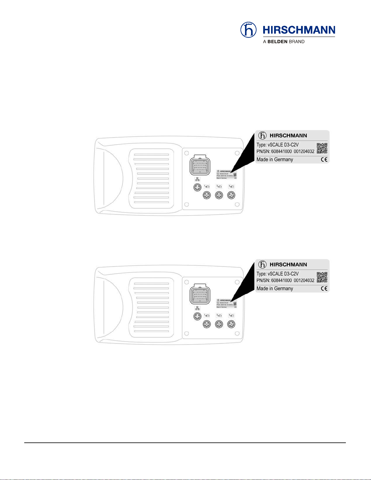
2.1Product Identification.................................................................................8
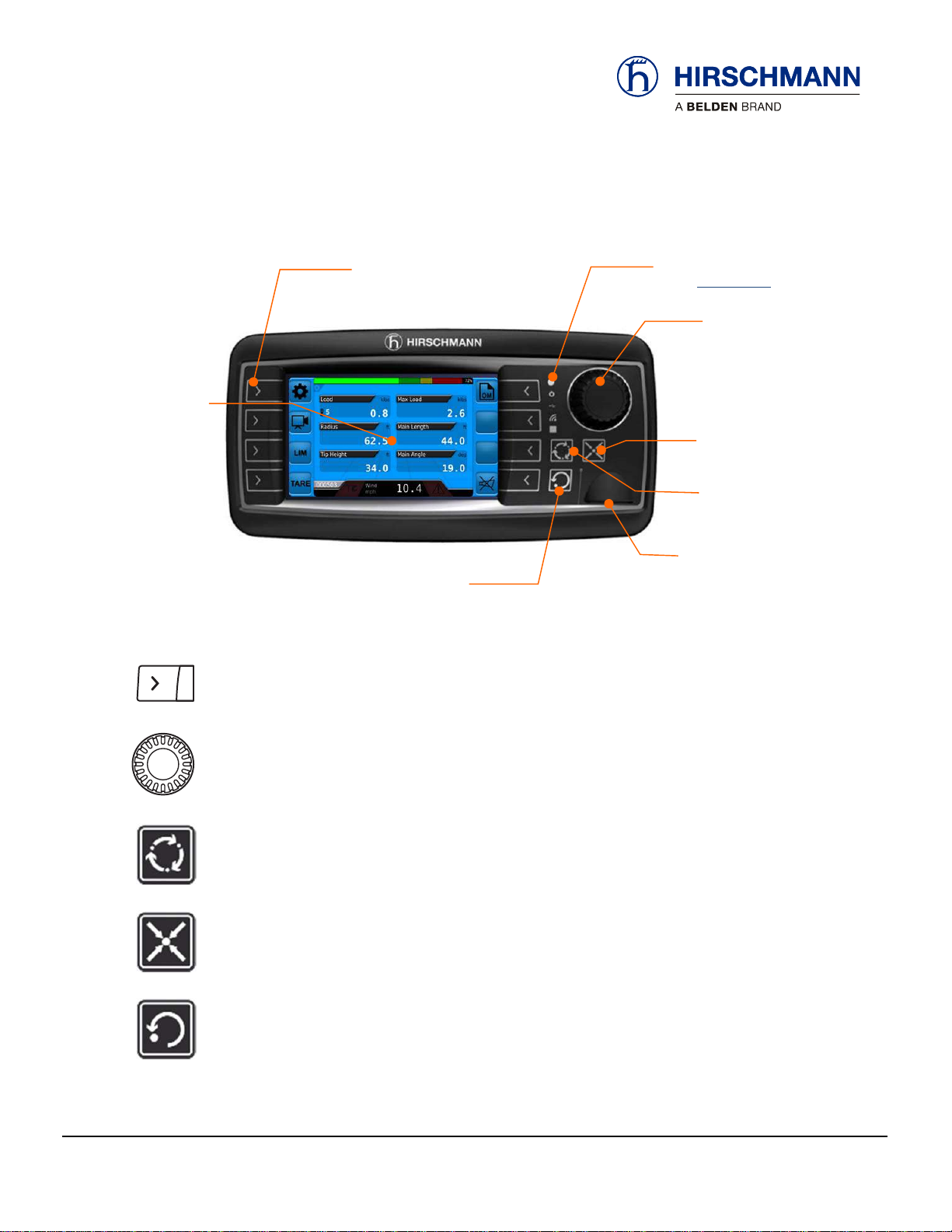
2.2Overview of Console Elements..................................................................9
2.3Overview Feedback Elements.................................................................10
3Operating Mode Selection.............................................................................11
3.1Switching Device On and Off...................................................................11
3.2Setting the Operation Mode.....................................................................13
4Operation.........................................................................................................16
4.1Main Working Screen ..............................................................................17
4.1.1Warning Lights / Audible Alarm ...........................................................18
4.2Work Area Limitations..............................................................................19
4.2.1Height Monitoring.................................................................................21
4.2.2Radius Monitoring................................................................................22
4.2.3Boom Angle Monitoring .......................................................................23
4.2.4Wind Speed Monitoring .......................................................................24
4.3Tare Weight .............................................................................................26
4.4Switching Off Audible Alarm....................................................................26
4.5Error Events.............................................................................................27
4.6Camera....................................................................................................28
5Service and Maintenance ..............................................................................29
5.1Settings Menu..........................................................................................29
5.2Machine Information ................................................................................30
5.2.1System Version Information.................................................................30
5.2.2Status of Digital Outputs......................................................................31
5.2.3Status of Digital Inputs.........................................................................32
5.2.4Readings of Analog Sensors...............................................................33
5.3User Screen.............................................................................................34
5.3.1LCD Brightness....................................................................................35
5.3.2Key Brightness.....................................................................................36
5.3.3Unit Selection.......................................................................................37
5.4Sensor Calibration ...................................................................................38

© 2018 Hirschmann Automation and Control GmbH · Mobile Machine Control Solutions · www.beldensolutions.com 3/53
qSCALE maestro (PLC v01.00.00) Operators Manual / Issue H (HMI v1.0.0) 01/2018 / rbm.
5.5System Information..................................................................................39
5.6Screen Capture........................................................................................40
5.6.1Taking Screen Captures......................................................................40
5.6.2Saving Screen Captures......................................................................40
5.7Maintenance and Repair..........................................................................41
6Appendix .........................................................................................................42
6.1Technical Data.........................................................................................42
6.2Password Entry........................................................................................43
6.3Error Codes Table ...................................................................................44
VERSION OVERVIEW
Issue Date Description Editor
A 10/2017 Initial Release (HMI v01.00.00) RBM
B 11/2017 Replaced Cover Image and added references to
vSCALE D2 Console RBM
C 11/2017 Added error code 1F01 handling information to section
3.1 Section 5.5 changed system information icon. RBM
D 11/2017 Section 5.5 changed system information icon. RBM
E 11/2017 Added Error Code List RBM
F 11/2017 Tweaked grammar, wording and formatting throughout
manual. RBM
G 12/2017 Corrected wording and moved Alarm Volume section
to the Service Manual. RBM
H 1/2018 Changed override alarm behavior. RBM

© 2018 Hirschmann Automation and Control GmbH · Mobile Machine Control Solutions · www.beldensolutions.com 4/53
qSCALE maestro (PLC v01.00.00) Operators Manual / Issue H (HMI v1.0.0) 01/2018 / rbm.
Introduction
This manual is a component of the equipment or systems supplied by Hirschmann Automation and Con-
trol GmbH. Keep this manual in a safe place and ensure that it is available to all users.
The contents of this manual are subject to change. Hirschmann Automation and Control GmbH do not
provide any guarantee for this material, including the associated guarantee regarding marketability and
suitability for certain intended purposes. Hirschmann Automation and Control GmbH accept no liability for er-
rors in the contents of the manual or for direct or indirect damage in connection with the provision and use of
the manual.
This manual is protected by copyright. All rights reserved. The manual may not be duplicated, repro-
duced or translated into another language, either wholly or partly, without the prior written permission of
Hirschmann Automation and Control GmbH.
The rendition of common names, trade names, trademarks etc. in this documentation should not be con-
strued to mean that such names, even without special identification, are free in the sense of trademark
and trademark protection legislation and hence usable by anyone.
This device/system is intended exclusively for the tasks described in this manual. Any other use shall be
construed as being inappropriate. The manufacturer accepts no liability for damage caused by inappro-
priate or impermissible use. This device / system may only be used if it is in perfect technical condition.
Only appropriately qualified personnel may work with this
device / system, i.e. persons:
who are familiar with the operation or installation and commissioning
who know the current regulations for the prevention of accidents
About this manual
Liability disclaimer
Copyright
notice
Trademarks
Use for the intended
purpose
Qualification of the
operating personnel

Safety Instructions
© 2018 Hirschmann Automation and Control GmbH · Mobile Machine Control Solutions · www.beldensolutions.com 5/53
qSCALE maestro (PLC v01.00.00) Operators Manual / Issue H (HMI v1.0.0) 01/2018 / rbm.
Marking of Notices
Dangers and other important notices are marked as follows in this user manual:
WARNING
Warning of direct threat of personal injury and damage to property.
Instructions on precautions to avert the danger.
CAUTION
Warning of dangerous situations. Also warns of damage to property.
Instructions for averting the danger.
IMPORTANT
Warning of possibly damaging situation for the product.
Instructions for avoiding the possibly damaging situation.
NOTE
Usage instructions and information, but no dangerous situation.
HINT
Supplementary comments and recommendations for the user.

Safety Instructions
© 2018 Hirschmann Automation and Control GmbH · Mobile Machine Control Solutions · www.beldensolutions.com 6/53
qSCALE maestro (PLC v01.00.00) Operators Manual / Issue H (HMI v1.0.0) 01/2018 / rbm.
1 Safety Instructions
WARNING
Imminent threat of personal injury and damage to property due to incorrect system settings!
The correct adjustment of the RCL to the current set-up status is essential for the correct function of
the system and of the machine.
The RCL can only operate correctly if all settings are entered correctly according to the current set-up
status during the SETUP procedure.
The settings can only be carried out by operators who are completely familiar with the operation and
functions of the machine and the RCL.
The correctness of these settings must be guaranteed before starting the machine operations!
IMPORTANT
Connection to the wrong power supply will cause damage to the device.
The device may only be connected to a DC voltage source of 10 V to 30 V!
1.1 EC Conformity Declaration
The technical design and construction of the qSCALE maestro system corresponds to requirements of
the EMC directive 2004/108/EC and therefore carries the CE symbol.
The device complies with the following standards:
EN 12895:200, EN 13309:2010, EN ISO 14982: 2009
The full conformity declaration is available from the manufacturer on request.

Product Description
© 2018 Hirschmann Automation and Control GmbH · Mobile Machine Control Solutions · www.beldensolutions.com 7/53
qSCALE maestro (PLC v01.00.00) Operators Manual / Issue H (HMI v1.0.0) 01/2018 / rbm.
2 Product Description
The vSCALE D2 / D3 maestro console is the interface of the Rated Capacity Limiter system (RCL).
The RCL monitors the sensors and detects a machine overload status depending on various parameters.
The machine driver is warned before the onset of an overload status via visual and audible warning signals.
The RCL comprises:
qSCALE S6 maestro central control unit
vSCALE D2 / D3 maestro console
various sensors for detection of machine status and environmental conditions
The vSCALE D2 / D3 maestro console is used for:
programming and inputting operating parameters
displaying the current machine operating data
NOTE
This user manual contains information about the vSCALE D2 / D3 maestro console,
mode selection, operation, sensor calibration and maintenance.
WARNING
Although the system incorporates functions for monitoring adjustable geometrical limit values
with visual and audible warnings and a relay output in the event of limit values being exceeded,
the system cannot be used as an operational limit switch.
The machine driver is responsible for the safe operation of the machine.

Product Description
© 2018 Hirschmann Automation and Control GmbH · Mobile Machine Control Solutions · www.beldensolutions.com 8/53
qSCALE maestro (PLC v01.00.00) Operators Manual / Issue H (HMI v1.0.0) 01/2018 / rbm.
2.1 Product Identification
The type plate carries the unique identification of the operating console. It is located on the back of the device.
Please ensure you make a note of all the information on your type plate for queries about this product.
Type plate
(Example for D3)
Type plate
(Example for D2)

Product Description
© 2018 Hirschmann Automation and Control GmbH · Mobile Machine Control Solutions · www.beldensolutions.com
9
/53
qSCALE maestro (PLC v01.00.00) Operators Manual / Issue H (HMI v1.0.0) 01/2018 / rbm.
2.2 Overview of Console Elements
Function Keys F1 to F12: Calls Functions
Encoder With Pushbutton Function: For Selection and Confirmation
SET key: Selects Settings / Silences Alarm
HOME key: Returns to Main Working Screen
ESCAPE key: Aborts Function
Display with
RCL Main Menu
Rotary Encoder with
Pushbutton Function
For Selection and Con-
firmation
"Set" Key
Selects Settings /
Silences Alarm
"Home" Key
(Return to RCL Main
Operating Screen)
"Escape" Key
Aborts Function / Returns to
previous screeen
Feedback Elements
(
See
Section 2.3
)
Function Keys F1-F8
(F1 – F12 in 7” display ver-
sion.) Function Varies by
screen
USB 2.0 interface
(used for service purposes)

Product Description
© 2018 Hirschmann Automation and Control GmbH · Mobile Machine Control Solutions · www.beldensolutions.com 10/53
qSCALE maestro (PLC v01.00.00) Operators Manual / Issue H (HMI v1.0.0) 01/2018 / rbm.
2.3 Overview Feedback Elements
Light Sensor: Not Used
Operating Display: Green While Supply Voltage is Connected
USB Data Display: Yellow During Data Exchange via Front USB Port
Wireless Indicator: Not Used
Multi-Function Light:
/ Flashes Red/White while in error state
Blue while setting the operating mode
Green while in operation
Yellow Machine nearing operational limit

Operating Mode Selection
© 2018 Hirschmann Automation and Control GmbH · Mobile Machine Control Solutions · www.beldensolutions.com
11
/53
qSCALE maestro (PLC v01.00.00) Operators Manual / Issue H (HMI v1.0.0) 01/2018 / rbm.
3 Operating Mode Selection
This chapter contains information, advice and instructions for choosing an operating mode.
3.1 Switching Device On and Off
The load limiting device has no on/off switch. The console automatically switches on with PTO power.
After boot-up, the following appears on the display:
Operating Mode Selection Screen
If the machine configuration has not changed, check
displayed configurations. If OK, press
Then check outriggers and confirm with
The Main Working Screen is then displayed.
If the machine configuration has changed see Setting
Operation Mode in Section 3.2
Initial Display After
Boot-Up:

Operating Mode Selection
© 2018 Hirschmann Automation and Control GmbH · Mobile Machine Control Solutions · www.beldensolutions.com
12
/53
qSCALE maestro (PLC v01.00.00) Operators Manual / Issue H (HMI v1.0.0) 01/2018 / rbm.
In the event of a system malfunction an error code is displayed in the bottom right of the display:
The error codes and what they mean are explained in the error codes table in Section 6.3.
The device is not ready for operation until all faults have been rectified and no error codes are displayed. The
error codes are displayed in red color. The warning codes are displayed in yellow color.
When confirming the operating mode, if the vSCALE D2/D3 maestro console does not have a working Ether-
net connection to the qSCALE S6 maestro central control unit, the operating mode will default to 0000 and
error code 1F01 will be displayed.
The vSCALE D2/D3 maestro console must be properly connected to the qSCALE S6 maestro central con-
trol unit, before confirming the operating mode. See the Service Manual for details.
System Malfunction?
Error code

Operating Mode Selection
© 2018 Hirschmann Automation and Control GmbH · Mobile Machine Control Solutions · www.beldensolutions.com 13/53
qSCALE maestro (PLC v01.00.00) Operators Manual / Issue H (HMI v1.0.0) 01/2018 / rbm.
Operating
Mode Code
3.2 Setting the Operation Mode
SETUP Procedure The RCL must be adjusted to the current machine setup status by completing the full SETUP
procedure after start-up and after any change to the machine configuration.
The system is not ready to operate until the full SETUP procedure has been completed.
WARNING
Imminent threat of personal injury and damage to property due to incorrect system settings!
The correct adjustment of the RCL to the current set-up status is essential for the correct func-
tion of the system and of the machine.
The RCL can only operate correctly if all settings are entered correctly according to the current
set-up status during the SETUP procedure.
The settings can only be carried out by operators who are completely familiar with the opera-
tion and functions of the machine and the RCL.
The correctness of these settings must be guaranteed before operating the machine!
Operating Mode Depending on the inputs during the SETUP procedure and on various sensor values, the deter-
mines the corresponding operating mode with the associated lifting capacity table. The operating
mode used by the system at any given time is displayed as a code in the status row:
Process The process for setting the RCL to the current machine status (SETUP procedure) includes the
following steps:
Entering Operating Mode selection screen from the Main Working Screen or automatically after the console is pow-
ered on.
Entering the number of rope reeving.
Selection of the hoist used.
Selecting the operating mode that matches the current outrigger and jib status.
Overview of inputs
NOTE
The process for setting the RCL to the current set-up status (SETUP procedure) will vary by
machine model. The following is an example machine.

Operating Mode Selection
© 2018 Hirschmann Automation and Control GmbH · Mobile Machine Control Solutions · www.beldensolutions.com
14
/53
qSCALE maestro (PLC v01.00.00) Operators Manual / Issue H (HMI v1.0.0) 01/2018 / rbm.
Selection Selection is with the rotary control:
Optionally press “up arrow” or “down arrow” function keys to select options.
Start SETUP
Operating Mode Setup can be called from the main RCL operating menu by pressing the
function key.
Select Reeving
Selection:
Press the button to enter the Select Reeving
Menu.
When the Reeving Button turns green you can
adjust the Reeving value.
Use rotary knob or up and down arrows to select
reeving amount.
Select Hoist
Selection:
Press the button to enter the Select Hoist Menu.
When the Hoist Button turns green you can
adjust the Hoist option.
Use rotary knob or up and down arrows to select Hoist.

Operating Mode Selection
© 2018 Hirschmann Automation and Control GmbH · Mobile Machine Control Solutions · www.beldensolutions.com
15
/53
qSCALE maestro (PLC v01.00.00) Operators Manual / Issue H (HMI v1.0.0) 01/2018 / rbm.
Select Operating
Mode
Selection:
Press the button to enter the Operatig Mode
Menu.
When the Operating Mode Button turns green
you can adjust the Operating Mode number.
Use rotary knob or up and down arrows to select the
operating mode that corresponds to the current
machine setup. Ensuring that the Jib and Outriggers
match the description shown on the right.
Confirm Selections
After selecting the appropriate modes
press or to set the selected operating mode.
Check that the outriggers are in the cor-rect position for the
selected mode and that the machine is stable
and press or .
The selected mode, reeving and hoist will be displayed.
Press or again to confirm the settings are
accurate and return to the Main Working Screen using the
newly selected operating mode.

Operation
© 2018 Hirschmann Automation and Control GmbH · Mobile Machine Control Solutions · www.beldensolutions.com 16/53
qSCALE maestro (PLC v01.00.00) Operators Manual / Issue H (HMI v1.0.0) 01/2018 / rbm.
4 Operation
After the operating mode is set, the RCL is ready to use.
The machine operator must be familiar with all operating elements of the RCL before operating the
machine.
All settings must be checked by hoisting a known load and comparing the information with that displayed by the
RCL.
WARNING
Imminent threat of personal injury and damage to property due to incorrect system settings!
The correct adjustment of the RCL to the current set-up status is essential for the correct func-
tion of the system.
The correctness of these settings must be guaranteed before operating the machine!

Operation
© 2018 Hirschmann Automation and Control GmbH · Mobile Machine Control Solutions · www.beldensolutions.com
17
/53
qSCALE maestro (PLC v01.00.00) Operators Manual / Issue H (HMI v1.0.0) 01/2018 / rbm.
4.1 Main Working Screen
The RCL Main Working Screen is the central operating image during machine operation and the start-
ing point for the selection of various functions. You can return to this screen from any other screen by
pressing the “Home” button.
Other indicators such as Jib Length and Jib Angle may be displayed on the Main Operating Screen and
can be set up in the Settings Menu.
Settings
(see Section 5.1)
Set or Disable Tare
(see Section 4.3)
Camera
(see Section 4.6)
Set Operating Mode
(see Section 3.2)
Work Area Limitations
(see Section 4.2)
Temporarily Mute Alarm (And after
muting, display warnings. See
Section 4.4)
Function keys with no assigned symbol are not active:
Function
Keys
Load Capacity
Utilization (Bar Chart)
Angle of Boom
Error Code,
Displayed as required
(See Section 4.5)
Rope Reeving
Current Load
Radius of Boom
Calculated Height of boom tip
Maximum Lifting
Capacity
Operating Mode
The Information Bar shows current
wind speed on the main screen
and maximum/current load on any
other screen.
Load Capacity
Utilization %
Length of Boom
Warning Lights
(See Section 4.1.1)

Operation
© 2018 Hirschmann Automation and Control GmbH · Mobile Machine Control Solutions · www.beldensolutions.com
18
/53
qSCALE maestro (PLC v01.00.00) Operators Manual / Issue H (HMI v1.0.0) 01/2018 / rbm.
4.1.1 Warning Lights / Audible Alarm
Various warning symbols are shown in the information bar as required and are visible from any screen:
Depending on the cause of the warning the following also occurs:
audible alarm is activated
error code is displayed (see error table in appendix)
status is recorded in the data logger
The audible alarm can be suppressed for a short period by pressing the function key. See Section
4.4 for more detail.
Early overload warning
This yellow symbol flashes to indicate that the machine load is or has already exceeded 90% of the safe
working load. An overload status may be imminent!
Overload/Error
This red symbol is lit to indicate that an error has occurred such as the maximum machine load has been
reached or exceeded.
The audible alarm sounds an uninterrupted tone.
RCL bypass
These red symbols flash on and off during the manual override of the power-off function of the safe load
indicator. This status is recorded in the data logger. An audible alarm will be triggered and may be muted by
the function key. (See Section 4.4 for more detail.)
Stroke End (A2B)
This red symbol lights up to indicate that a two-block event has occurred.
A stroke end status is recorded if the load block comes into contact with the boom head. There is a danger in
this case that the lifting rope will break and the load will drop. A stroke end state can be caused by the load
being pulled against the boom head or the boom being extended or raised without playing out the lifting rope.
The audible alarm sounds an uninterrupted tone.
Example
Acknowledging
Alarm
Error Code
Warning Symbols

Operation
© 2018 Hirschmann Automation and Control GmbH · Mobile Machine Control Solutions · www.beldensolutions.com
19
/53
qSCALE maestro (PLC v01.00.00) Operators Manual / Issue H (HMI v1.0.0) 01/2018 / rbm.
4.2 Work Area Limitations
The RCL system has programmable functions for monitoring geometrical limits of the working area:
Height Monitoring > See Section 4.2.1
Radius Monitoring > See Section 4.2.2
Boom Angle Monitoring > See Section 4.2.3
Wind Speed Monitoring > See Section 4.2.4
Programming is carried out via an interactive menu.
The functions can be set individually or in combination. Active limit values are indicated by the display of color-
highlighted symbols.
Exceeding a programmed limit value causes a corresponding color change in the limit symbol on the main
menu to be displayed and an audible alarm warning to be sounded.
Blue
No Limits Set
Green Within Valid Limits
Yellow Warning Condition / Approaching Limit
Red Outside Limit
Color Meanings

Operation
© 2018 Hirschmann Automation and Control GmbH · Mobile Machine Control Solutions · www.beldensolutions.com
20
/53
qSCALE maestro (PLC v01.00.00) Operators Manual / Issue H (HMI v1.0.0) 01/2018 / rbm.
CAUTION
Machine movements are not switched off when limit values are exceeded.
Angle Limit
(see Section 4.2.3)
Wind Speed Limit
(see Section 4.2.4)
Radius Limit
(see Section 4.2.2) Deactivate all Limits
Height Monitoring
(see Section 4.2.1)
The colors of the function buttons and symbols will change depending on the state of the limit.
Function
Keys
Radius Limit
Angle Limit
Color Meanings:
Limit inactive or not
programmed
Limit active
Limit Nearing
Maximum Value
Limit value reached
or exceeded
Height Limit
Wind Speed
Limit
This manual suits for next models
2
Table of contents