Belsaw 1080 Use and care manual

1080 Abrusive Belt Grinder
MODEL TOSO ABRASIVE BELT GRINDER OPERATING
INSTRUCTIONS AND PARTS LIST
SPDCIFICATIONS:
OVERALL SIZE:
WORK TABLE SURFACE:
TABLE TILT ANGLLS:
MOTOR:
STANDABD FEATURES
SPECIAL SEALED BALL BEARINGS IN DRIVE WHEELS
ADJUSTABLE IDLER ARM _ USED FOR BELT SUPPORT ON PRECISION INSIDE WORK
SELF-ALIGNING UPPER WHEEL - AUTOMATICALLY ALIGNS BELT WITH LOWER WHEEL
PRECISION GROUND TABLE EASILY LOCKED AT ANY ANGLE _ ASSURES EVEN GRINDING
AUTOMATIC BELT TENSION _ INSURES LONG AND EVEN BELT WEAR
QUICK BELT CHANGE _ USES I" X M" ABRASIVE BELTS
8.5 INCHES WIDE
I4.O INCHES DEEP
22.0 INCHES HIGH
8.5 INCHES WIDE
7.0 INCHES DEEP
20" BACK MAXIMUM
70" FORWARD MAXIMUM
I/4 HORSEPOWER
I75O RPM
IIOV, 60 CYCLE AC
IIIACHINDRY CO liilol Equitable Bd., Bor 593 o f,ansas Gity,-to. 6f1{1 1dffia
INDEX
INTRODUCTION
SAFETY RECOMMENDATIONS
GLOSSARY OF TERMS
PARTS LIST
PARTS ITLUSTRAT1ON
r0B3 (FLOOR STAND) PARTS rrST.
rOB4 MOTOR MOUNT
ASSEMBLY INSTRUCTIONS FOR IO8O BELT GRINDER AND TO83 FLOOR STAND .
BELT INSTALLATION
BELT ALIGNMENT
ABRASIVE BELTS .
CIRCUTAR SAW SHARPENING ON THE TO8O BELT GRINDER
TOOTH K)INTS .
BACK BEVELING .
SHAPING SAW TEETH ON THE TOBO BELT GRINDER .
SCISSORS
PINKING SHEARS .
CHISELS.
SCREWDRIVER .
ROTARY TAWNMOWER BLADES
AXES, HATCHETS, AND CLEAVER WEDGES.
GARDEN TOOLS
HEDGE TRIMMERS
HEDGE SHEARS
SETNNG UP FOR INSIDE GRINDING .
SHARPENING KNIVES USING THE #27I KNIFE SHARPENING FIXTURE .
GENERAL SHOP TIPS
I
2
3
4
5
6
6
7
I
9
l0
tl
t2
r3
t4
r6
t7
l8
r9
r9
2l
22
23
2/L
25
%
27
I
'1
l
l
l
INTRODUCTION
The Belsaw Abrasive Belt Grinder will sharpen just about anything in your shop, in less time and with less
work. It will sharpen scissors, mower blades, knives, chisels, drills, saw teeth - virtually all cutting edges.
Designed for quick easy sharpening, the belt ginder does not burn - your finished work is smooth, sharp,
artd clean of burrs.
The Model 1080 can also be used for cleaning, sanding, carving, polishing and shaping of wood, plastic, and
metals. It's perfect for those inside edges that are hard to sharpen using other methods.
The 1080 abrasive belt grinder is a heavyduty, rugged grinder, built to industrial standards for years of
continuous use. It has been carefully tested" inspected and packed at our factory and was delivered to the
shipperin good condition. Upon receiving your equipment, inspect the shipping cartons for signs of damage
and check your equipment carefully. Using the part numbers and description, make a list of any damaged
or missing parts and immediately write the Customer Services Department, Belsaw Machinery Co.
We will then furnish the necessary repair parts and instructions for filing dar.naSe claim, or insfructions
for returning the equipment to our factory for exchange.
Your new Belsaw is guaranteed for one year from date of purchase against faulty workmanship or defective
parts. If any part should need replacement, write our Customer Service Delnrhent.
MACHINDRY GO 6801 Equitable Rd., Bor 593 o Kansas Gi$, ltlo. 64141 6ffim
Pagc 1

SAFETY RECOMMENDATIONS
1. Before using your new Belsaw gnnder read your instruction manual carefully' From it you'll learn
the operation and the applications you can perform'
2.Alwaysmakesureyourmotorswitchisoffwhenplugginginpowercord.
3. Always wear safety gtasses or face shield when the grinder is in operation'
4. Remove rings, watches and ties. Do not wear loose-fitting clothing'
5. U.pLrg power cord before making adjustments or changing belts'
6. Be sure to remove any adjusting wrenches or tools before starting equipment'
z. Keep hands away fron abrasive surface. Maintain control of your work at'all times- Position yourself
so you don,t have to overreach to do the work. Keep proper footing and balance at all times'
g. Never operate your belt grinder in a damp or wet location. The work area drould be well lighted'
g. Make sure the belt tracks ProPeily on the Pulley.' Adi'sment procedures are included later in
this manual
P*2
i
(
\
I
I
BEVEL
CANNELL EDGE
CHALK-LINE .
BACK.CLEARANCE
FINISH.SHARPENING
FLAT-GRIND .
FREDHAND GRINDING
GUMMING .
HOLLOW.GRIND
HONING .
HOOK ANGLE
JOINTING
LOADING
SETTING
SHAPING
SHINER .
GTOSSARY OF TERMS
The angle on a cutting surface of a tool or blade. A"d" varies depending on
the purpose of the tool or blade.
Rolled edge on digg"g tools to reduce nicking by rocks or other sharp
objects.
Line drawn on wood table as a guide for even sharpening of each tooth.
Refers to basic shape of the back of tooth on circular sawblades. Back of
tooth must b€ ground lower than the tooth point so it clears the wood
being cut.
Achral sharpening or beveling of the teeth on a sawblade.
Refers to grinding the face of tooth on circular blades without angle. Can
also refers to grinding the cutting surface flat as opposed to hollow grinding.
Grinding a cutting surface without use of a guide.
Refers to grinding, shaping or increasing the depth of the gullet on a circular
sawblade.
Grinding the cutting srrface with a slightly eoncave edge. Can be used on
chisels and similar tools.
Cleaning up and resharpening to a very fine edge.
A"d" between a line drawn along the face of a sawblade to a line from the
tooth point to the center hole.
Sometimes cdled rounding, dhe first step in resharpening circular sawblades.
It brings the blades to a tme cutting circle with every tooth the same length.
Befers to build+p on abrasive belts, primarily from wood or duminum.
Describes a method of providing clearance in the cut of material being
sawed eo that the blade does not bind in the cut.
Restoring origind ehape of teeth on blades or tools.
Flat spot on point of circular sawblades left after jointing.
*
t- ---"
he. 3
l
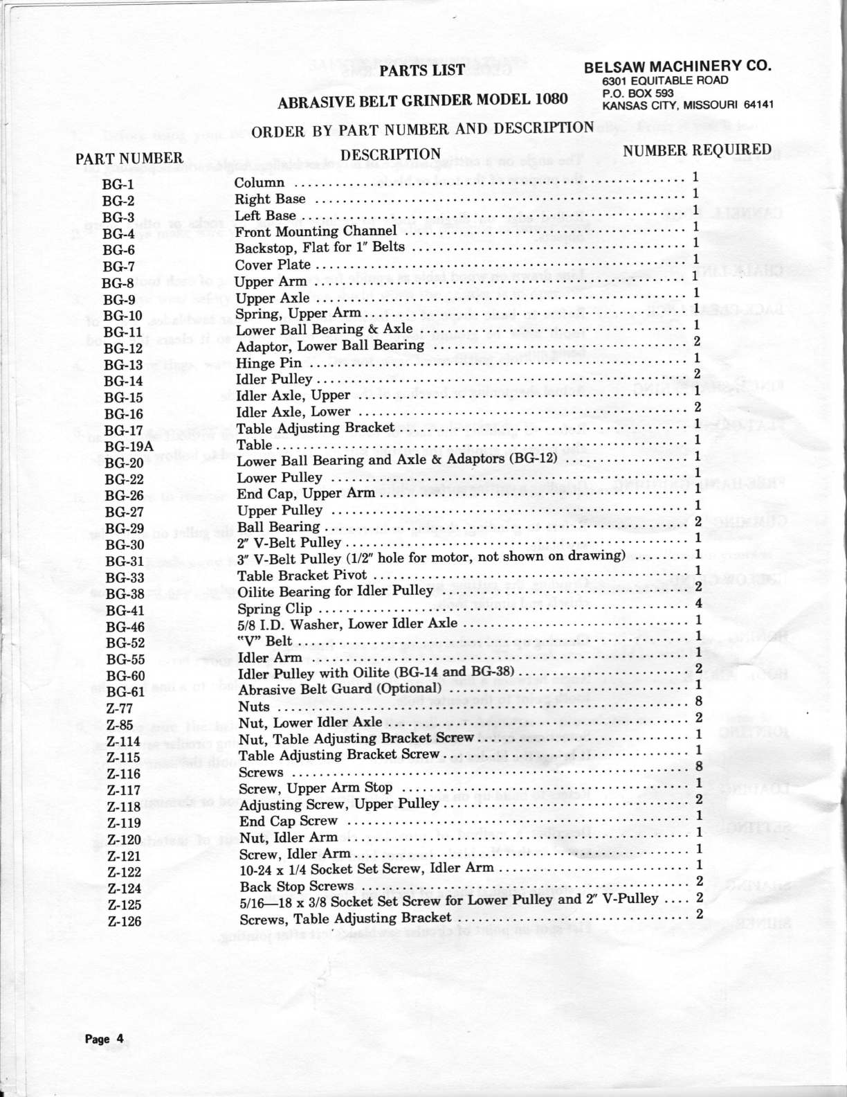
PART NUMBER
BC'.1
BG.2
Be*3
BCF4
BG-6
BG7
Bc-8
Be'-9
Bc'.lO
BCr.11
BC-12
BG13
BG-14
BCr15
BC-16
Bcr.17
BG-194
BG-20
Be*22
BG-26
BG-27
8G.29
BC-30
BC*31
BG'33
BC*38
BG41
Bc*46
BG-52
BG55
BG60
BG-61
z-77
7-85
Z-LL4
z-r15
z-rL6
Z.LT?
z-Lt$
Z-LLg
z-t20
z-tzL
z-r22
2-124
z-t25
7-126
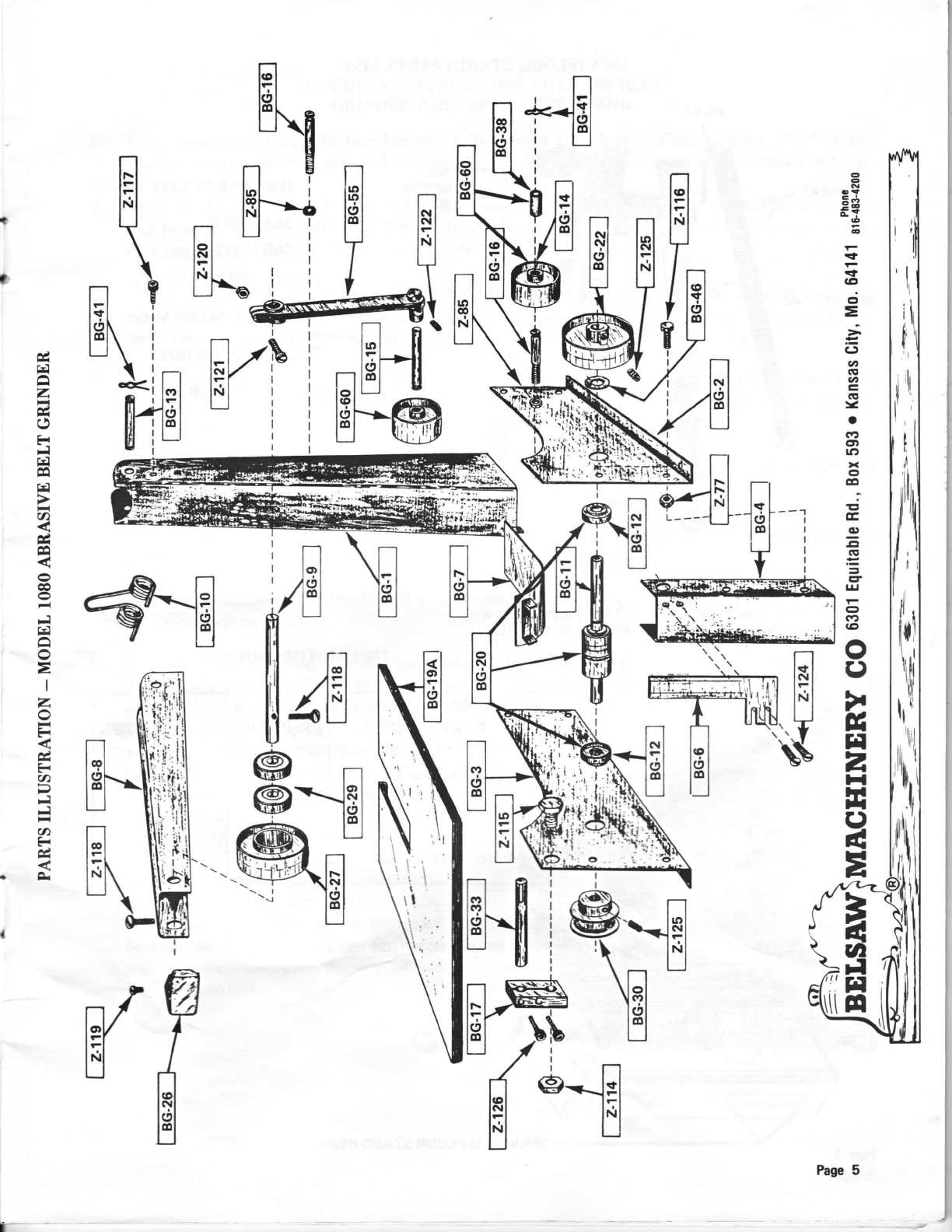
PARTS IIST BELSAW MACHINERY CO.
6301 EOUITABLE ROAD
ABRASIVE BELT GRINDER MODET 1080 firfiitrJ"ffi,, MrssouR! 64141
ORDER BY PART NUMBER AND DESCRIPTION
DESCRIPTION NUMBER REQUIRED
Column """"' 1
RightBase . ""' I
Left Base
Front Mounting Channel
Backstop, Flat for 1" Belts
Cover Plate .
Upper Arm .
Upper Axle .
Spring, Upper Arm.
Lower Ball Bearing & Axle
Adaptor, Ipwer Ball Bearing ....
Hinge Pin ..
Idler Pulley
1
1
1
1
ldler Axle, Upper
Idler Axle, Lower
Table Adjusting Bracket
Table
Lower Ball Bearing and Axle & Adaptors (BG'12)
Lower hrlley
End Cap, Upper Arm ....
Upper Pulley
Ball Bearing ....
? V-Belt Pulley
3" V-Belt Pulley (1/2" hole for motor, not shown on drawing)
Table Bracket Pivot '
Oilite Bearing for Idler hrlleY ..
Spring Clip .
5/8 I.D. Washer, Iower Idler Axle
,.v"'Belt
Idler Arm
Idler hrlley with Oilite (BeFf4 and BC-il8)
Abrasive Belt Guard (OPtional)
Nuts .
Nut, Lower Idler Axle
Nut, Table Adjusting Bracket Screw
Table Adjusting Bracket Screw
Screws
Screw, Upper Arm StoP
Adjusting Screw, UPPer PulleY
End Cap Screw
Nut, Idler Arm .
Screw, Idler Arm
10-24x 1/4 Socket Set Screw, Idler Arm
Back Stop Screws
5/1L18 i glA So"k"t Set Scnew for Lower Pultey and.t V-Pulley ....
Screws, Table Adjusting Bracket
Page 4
lrI
Ir
"il
l}'
'lrl
o
e
r?
=6
=6
.A
5
-t
-f
a9
cl
=
j
i5
v,
.E
at
(rg
-a
GD
€tt
rl':,
x
ct
o
E
E
ct
-cl
6g
=
=
E
lrl
e
c:t
G'
o
C)
)r
fr
rt
2
t{
H
*t
C)
d
E
a
a
]t
H
n
FI
llel
I lntl
-u
**lil
r13
I
e
e
EI
lEl
\
ni
lSl-a
EI LJ i
tl.'\ i i
\
KT
Ti
l
c
H
a
z
c
()
Ed
Ff
frl
c0
H
a
E
o
c
co
o
Ff
14
a
o
=
I
z
o
Fr
&
F
U)
Ff
Fl
a
F
c
oA.
EZ,,b
N:
@
I
t4
Page 5
t-
8G.59
BG-56A-
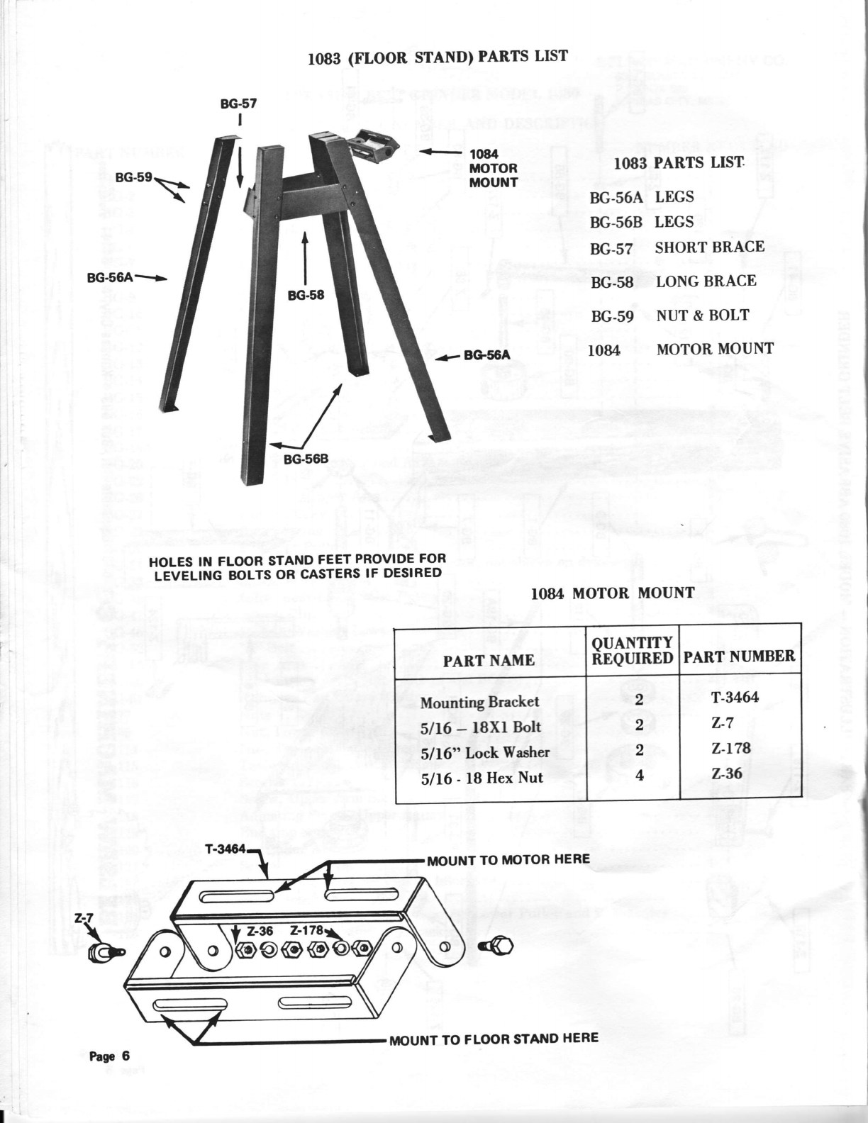
1083 (FLOOR STAND) PARTS LIST
-e BG56A
IO83 PARTS LIST.
BG.56A LEGS
BG-568 LEGS
BG.s? SHORT BRACE
BG.58 LONG BRACE
BG-59 NUT & BOLT
IO84 MOTOR MOUNT
rO84 MOTOR MOUNT
HOLES IN FLOOR STAND FEET PROVIDE FOR
LEVELING BOLTS OR CASTERS IF DESIRED
IIIOUNT TO TIIOTOR HERE
PART NAME QUANTITY
REQTIIRED PART NUMBER
Mounting Bracket
5116 - lSXr Boh
5116" Lock Washer
5116 - l8 Hex Nut
2
,
2
4
T-346/!
z-7
z-t78
z-%
Pas.6 MOUNT TO FLq)R STATTID HERE
l.
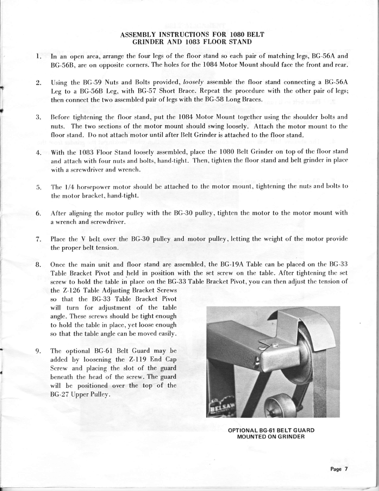
ASSEMBLY INSTRUCTIONS FOR IOSO BELT
GRINDER AND IO83 FLOOR STAND
In an open area, arrange the four legs of the floor stand so each pair of matching legs, BG-56A and
BG-568, are on opposite corners. The holes for the 1084 Motor Mount should face the front and rear.
2. Using the BG-59 Nuts and Bolts provided, loosely assemble the floor stand connecting a BG-56A
Leg to a BG-56B Lcg, with BG-57 Short Brace. Repeat the procedure with the other pair of legs;
thcn connect the two assembled pair of legs with the BG-58 Long Braces.
Befort: tightening the floor stand, put the l0B4 Nlotor I\tount together using the shoulder bolts and
nuts. The two sections of the motor mount should swing loosely. Attach the motor mount to the
floor stand. Do not attach motor until after llelt Grinder is attached to the floor stand.
With the l0B3 Floor Stand loosely assembled, place the l0B0 Relt Grinder on top of the floor stand
and attach with four nuts and bolts, hand-tight. 'l'hen, tighten the floor stand and belt grinder in place
with a screwdriver and wrench.
The ll4 horsepower motor should be attached to the motor mount, tightening the nuts and bolts to
the motor bracket, hand-tight.
After aligning the motor pulley with the BG-30 pulley, tighten the motor to the motor mount with
a wrench and screwdriver.
Place the V belt over the BG-30 pulley and motor pulley, letting the weight of the motor provide
the proper belt tension.
Once the main unit and floor stand are assembled, the BG-I9A Table can be placed on the BG-33
Table Bracket Pivot and held in position with the set screw on the table. After tightening thc set
screw to hold the table in place on the BG-33 Table Bracket Pivot, you can then adjust the tension of
the 2-126 Table Adjusting Bracket Screws
so that the BG-33 Table Bracket Pivot
will turn for adjustment of the table
angle. These screws should be tight enough
to hold the table in place, yet loose enough
so that the table angle can be moved easily.
9. The optional BG-61 Belt Guard may be
added by loosening the Z-lI9 End Cap
Screw and placing the slot of the guard
beneath the head of the screw. The guard
will be positioned over the top of the
BG-27 Upp"r Pulley.
OPTIONAL 8G.61 BELT GUARD
MOUNTED ON GRINDER
I
t3.
4.
5.
6.
7.
B.
Page 7

BELT INSTATLATION
The BG-B upper arm is mounted to the BG-r corumn and has spring tension created by the BG'ro upPer
arm spring. The following procedure should be used to install new belts:
l. With the table tilted forward depress BG-B upper arm'
Place belt so it runs over BG-27 upper pulley and in front of the BG-6 backstop'
Thread the belt around the BG-22lower pulley and the BG-f 4 idler pulley'
The abrasive belt will run in a counter-clockwise direction when looking at the grinder from the
right side. Make sure the arrow on the back of the belt points in this direction. If the belt travels
inthe opposite direction of the arrow, it may separate after very little use'
when the BG-8 upper arm is released the belt will have the proper tension'
t
2.
3.
4.
).
Page 8
:;t+:::\

BELT ALIGNMENT
(THE BG26 E'UD CAP HAS BEEI{
REMOVED FOR I LLUSTRATIVE PURPOSESI
If you find that your abrasive belt tracks to the right or left, the following adjustments may be made:
l. Unplug power cord.
2. If the belt tracks to the right, tighten the Z-ll8 adjusting screw going through the axle from
the bottom, and loosen the adjusting screw going through the axle from the top.
3. If the belt tracks to the left, reverse the procedure in step 2.
4. Tum on the equipment and check belt travel.
5. If final adjustments are necessay, make sure power cord is unplugged.
he. 9

ABRASWE BELTS
whenorderingabrasivebelts,weofferthefol|owinginfo'mationssaguideline.sin€eeschoPeretofusesa
different .,touch", a trial order of each belt and personal experience should be the determining factot as to
which belt iB best Buited to your needs,
COARSE
40"GRIT: This ie the courBest b€lt i{e heve available. Hobbyirts 6nd this the b€st belt for rough'ehaping
wood eince the belt will not tend to..load". Used on metal only when fart removal of stock is required
such as removing the deep nicls in mower bladee snd other general shaping'
MEDIUM.COARSE
60-GRIT: Good on wood, but al6o csn be used on a wide variety of metels (including a.luminum) as well ae
plesticE. W€ suggest touching the moving b€lt with candle wax or paraffin to ke€P the b€lt from "loading"
when you are grinding eluminum.
MEDIUM
B0-GRIT:Veryclos€intextuetothefamiliarMediumlfi)gritbelts,butthecoarsergritandheavier
backing will tend to make the belt wear longer than the 100€dt' Sharpening shop operators will find it
useful for rough shaping heavy cutting tools such a6 axes, hatcheb or graE6 whiPs'
M[,DIUM.FINE
l00"cRIT: Good for finbh sharpening most cutting tools srch rs rotary mower bl,erles. once the majority
of the g r has worn ftom the b€lt, msny experienced ope.rtors sct the belt aside for fine'fini6h sharyening.
NNE
lSocRIT: Hsving the 6nest grit, it dso has the lighteet backing rnd will tend to wesr fs5te.. used to bring
up the finest cutting edges on tools such ss sciesors, pinking eheere, cutlery rnd other light cutting tools
The fine grit produces almoet a honed edge. This belt worke cxtr€mely well for removing the sharp edge
on cut gho8, which hobbyiste and handymen will find extremely us€ful'
I
I
a
t.
Pre. f0

CIRCULAR SAW SHARPENING ON THE TOOO BELT GRINDER
A circular grw vrill cut clcrnly rnd earily only whcn it is round and sharP, md the teeth hrvc the p.oP€r
gide and beck cle&rnco. Thc l08O bclt grindcr will enrble you to bevel-grind, flat-grind end eharpen
I circulrr srw teeth in leas time and without h.viDg to ttotty lbout buming the s'rv tcclh'
I
Before eherpening r sawblede on the bclt grinder, the following steps must l,€ accomPli6hed:
f. JOINTING - Sometimos cdled rounding, the first 8t€P in.4hrrPening citculrr sawblade* It
bringr the blade to r truc cutting citcle vith evcry tooth th€ 6rme lcngth.
2. GUMMING - Refels to grinding, shaPing or increasing the depth of the gull€t on . circular
aaw blarle,
3. SETTING - Terrdinolo6r used to descdhe e method of providing cleerence in the cut of
material being sarved, 60 thst the blade does not bind in the cul.
After these stepe have heen accomplirhe{ you ,r€ now rcady to sherPen dre teeth on the sarvblade. The
ectual eha4rning or beveling of the t€€th on a sawbhde is notmally rdened to ra finirh+herpening.
h! 1l
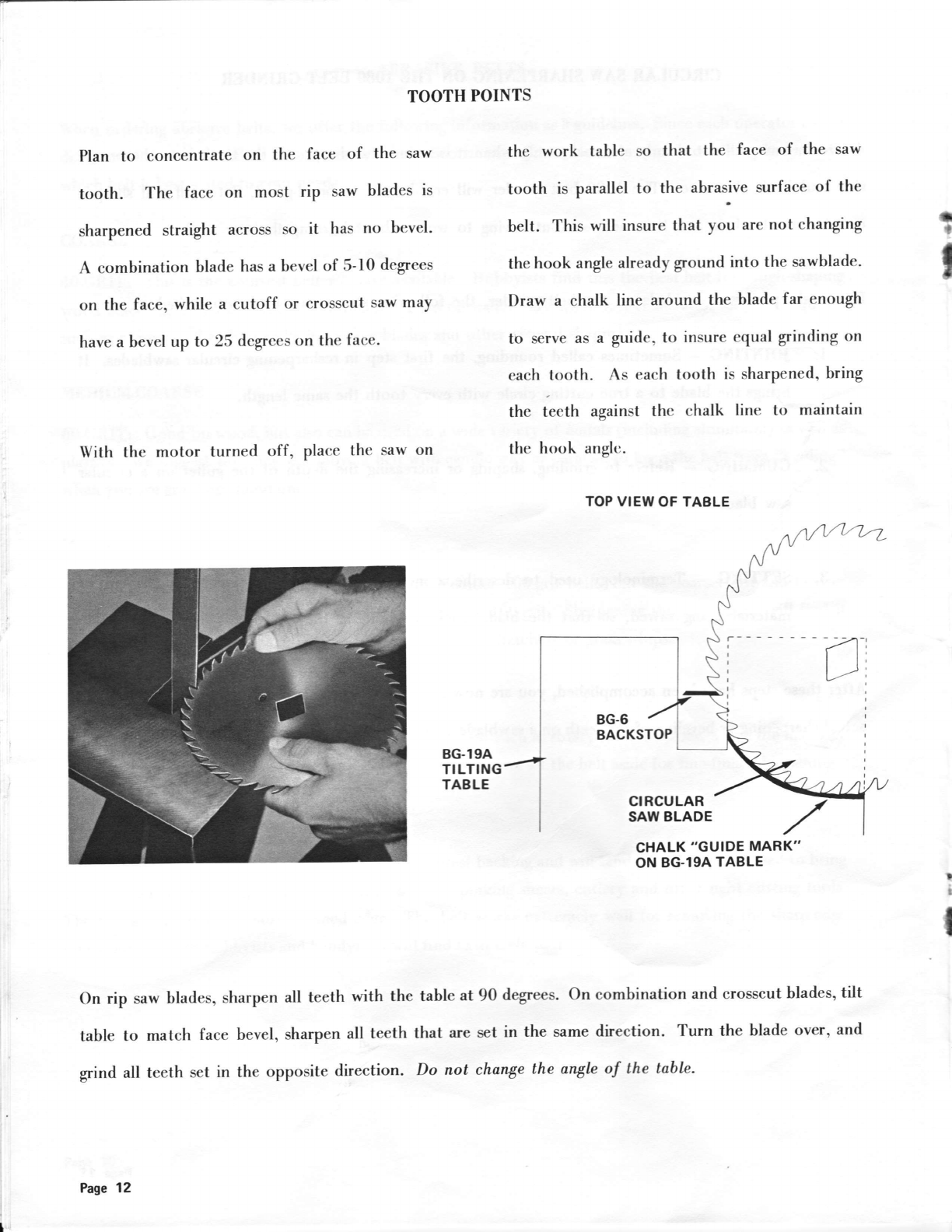
TOOTH POINTS
Plan to concentrate on the face of the saw
tooth. The face on most rip saw blades is
sharpened straight across so it has no bevel-
A combination blade has a bevel of 5-10 degrees
on the face, while a cutoff or crosscut saw may
have a bevel up to 25 degrees on the face.
With the motor turned off, place the saw on
the work table so that the face of the saw
tooth is parallel to the abrasive surface of the
belt. This will insure that you are not changing
the hook angle already gound into the sawblade.
Draw a chatk line around the blade far enough
tb serve as a guide, to insure equal grinding on
each tooth. As each tooth is sharpened, bring
the teeth against the chalk line to maintain
the hook anglc.
TOPVIEWOF TABLE
a
t
I
I
It
CTIALK "GUIDE iIARK"
Oil BE19A TABLE
On rip saw bladeso sharpen all teeth with the table at 90 degrees. On combination and crosscut blades, tilt
table to match face bevel, sharpen all teeth that arc set in the same direction. Turn the blade over, and
grind all teeth set in the opposite direction. Do not change the anglc of the tablc.
tI
I
l,t
I
i
Pqe 12

t
i
BEVEL TOP OR BACK JUST
TO THE TOOTH POINT BEVEL SHOULD CURVE SMOOTHLY
INTO BACK OF TOOTH
BACK.BEVELING
Beveling the top or back of a saw tooth can also be accomplished on grinder. Adjust the table to the bevel
angle required on the top or back of the tooth. Plan to make the first contact of the tooth against the belt
slightly in back of the tooth point. After the sawblade has contacted the belt, use pressure to grind the top
until the bevel just extends to the tooth point. Do not grind off the tooth point, as this will cause the saw
to be out of round. Grind this bevel so the end of the bevel curves smoothly into the back of the tooth.
A general guide to the amount of metal to be removed is the size of the flat or shiner left by jointing. If
the shiner is small, you can complete the sharpening in one pass around the blade. If there is a relatively
large shiner, it is better to make several passes around the blade.
Almost any style blade can be sharpened on the abrasive belt grinder. If the style is new to you, it's best
to adjust the table angle and experiment with a sawblade before actually sharpening it on the belt grinder.
Page 13
SHAPING SAW TEETH
After a saw has been filed by hand, or ground
several times, the saw teeth may need reshaping.
The coolness of the l0B0 makes it ideal for
reshaping, as it enables you to stay on the tooth'
ON THE IOSO BEIT GRINDER
bringing it back to shape without worrying
about overheating or bluing the tooth. Basic
shaping of saw teeth should be accomplished
with table kept flat at 90 degrees to the bilt. I
I
I
I
The belt grinder is especially useful for shaping Style C teeth, as the one-inch wide belt lets you do the
entire top of the tooth in one pass. Also, this step gives you the back clearance required for properly
sharpened sawblades. With the motor turned off, set the sawblade on the table so that the top of the tooth
is parallel to the belt. Mark the circumference of the sawblade with a chalk line.
Page 14
Using the chalk line as a guide, sharpen each tooth to the same back clearance.
Saw teeth with curved backs can also be shaped. Start grinding just in back of the tooth point. Turn
the saw to grind down the back of the tooth to bring the curve back into the rounded gullet smoothly
and evenly.
T
t
I
tCutoff saws and some combination blades such as
Style S blades will have a bevel all the way down
the back of the tooth. When shaping this type
blade on the grinder, tilt the table to the recom-
mended bevel, rather than at 90 degrees to the
belt. In this way, when the final bevel ginding is
accomplished on the sawblade, you will not have
to remove an excessive amount of metal.
Pagc 15

, SCISSORS
Although scissors, like many other tools, can be sharpened, without a holder, we recommend using the
#264 tool holder until familiar with the basic operation. Clamp the blade to be sharpened in the holder,
with the beveled edge down. Tilt the table to the desired (3 degree to 5 degree) angle and make a light pass
across the belt, removing only enough metal to create a sharp cutting edge. Grind free hand matching any
curve of the blade.
I
I
I
P!e. 16

I
I
PINKING SHEARS
Sharpened in a manner similar to scissors, plan
to sharpen only the beaeled cutting edge. Neuer
attempt to sharpen the V-grooues. If the grooves
have previously been filed or sharpened, the
shears should be returned to the manufacfurer
for factory service.
Reproduce the original bevel as closely as
possible. Place the shears on the work table
or in the tool holder, positioning the table to
match the bevel of the shears. After making a
light pass across the abrasive belt, visually inspect the area being sharpened and readjust table tilt if
necessary. Taking light passes, follow the natural contour of the blade. Remove only the minimum
amount of metal for a sharp edge.
You may find it necessary and
more convenient to disassemble the
shears prior to sharpening. A tool
to remove the special type fulcrum
nut can be made from a common
bottle cap opener as shown in the
picture at right. After sharpening
be sure all parts are replaced in
their original order. Clean all parts
and applylight machine oil sparingly.
the tension of the fulcrum nut after final sharpening.
t
I
For maximum cutting efficiency, adjust
Page 17

CHITIEI,s
Clamp chisel in the 264 tool holder bevel-edge
down. Tilt the work table so that the bevel
rnatches the bevel on the chisel. To insure a
straight grnd, clamp a guide on the table and
slide the holder and chisel across the belt with
the holder resting on the guide.
t,SIlTG THE HOLDER
FIRST BEVEL CUT CORRECTED BEVEL CUT
If the shaft of the chisel is too short to fit
in the tool holder, the grinding may be
done free-hand, resting the chisel on the
work table;or by holding the chisel securely
in your hand. Make a light pass - if the
bevel is not exactly straight, move the
handle of the chisel to the right or left
until the bevel angle is straight with the
shaft of the chisel.
I
I
t
I
t
Page 18
FREE HAI{D
Table of contents
Popular Grinder manuals by other brands

Parkside
Parkside 336699 1910 Original instructions

Ingersoll-Rand
Ingersoll-Rand AC4A Series Product information

Beta
Beta 1933IH Operation manual and instructions

Makita
Makita DLX2164X instruction manual

Hitachi
Hitachi G13SC2 - 125mm Grinder 1200W Back Handle... parts list

Parkside
Parkside PWS 230 B2 instructions


