Benning DUSPOL digital LC User manual

V
�
�
690
6 . . .
690V
400
230
120
50
24
12
digital LC
DBedienungsanleitung
Operating manual
FMode d‘emploi
EManuel de instrucciones
Инструкция за
експлоатация
Návod k použití
zkoušečky
Käyttöohje
Οδηγίες χρήσεως
H Használati utasítás
IIstruzioni per l’uso
Naudojimosi instrukcija
NBruksanvisning
Gebruiksaanwijzing
Instrukcja obsługi
Instrucţiuni de Utilizare
Инструкция по
эксплуатации
индикатора
напряжения
SBruksanvisning
Kullanma Talimati
Priručnik za upotrebu
DUSPOL
®
digital LC
geprüft und zugelassen

V
�
�
690
6...
690V
400
230
120
50
24
12
digital LC
12/ 2008
DUSPOL
®
digital LC
D F E H I N S
T.-Nr. 756223.00/ 12-2008
4
3
2
5
6
7
8
9
J
K
L
M
N

12/ 2008
DUSPOL
®
digital LC
3
D D
Bedienungsanleitung
DUSPOL®digital LC
Bevor Sie den Spannungsprüfer DUSPOL®digital LC
benutzen: Lesen Sie bitte die Bedienungsanleitung
und beachten Sie unbedingt die Sicherheitshinweise!
Inhaltsverzeichnis:
1. Sicherheitshinweise
2. Funktionsbeschreibung des Spannungsprüfers
2.1 Messstellenbeleuchtung
2.2 Hold-Funktion
3. Funktionsprüfung des Spannungsprüfers
4. So prüfen Sie Wechselspannungen
4.1 So prüfen Sie die Phase bei Wechselspannung
5. So prüfen Sie Gleichspannungen
5.1 So prüfen Sie die Polarität bei Gleichspannung
6. So prüfen Sie die Drehfeldrichtung eines Dreh-
stromnetzes
7. So prüfen Sie eine elektrisch leitende Verbindung
(Durchgangsprüfung)
8. Batteriewechsel, Anzeige der Batteriespannung
9. Technische Daten
10. Allgemeine Wartung
11. Umweltschutz
1. Sicherheitshinweise:
- Gerät beim Prüfen nur an den isolierten Handhaben/
Griffen Aund Banfassen und die Kontaktelektro-
den (Prüfspitzen) nicht berühren!
- Unmittelbar vor dem Benutzen: Spannungsprüfer auf
Funktion prüfen! (siehe Abschnitt 3). Der Spannungs-
prüfer darf nicht benutzt werden, wenn die Funktion
einer oder mehrerer Anzeigen ausfällt oder keine
Funktionsbereitschaft zu erkennen ist (IEC 61243-3)!
- Der Spannungsprüfer darf nur im Nennspannungs-
bereich von 6 V bis AC 690 V/ DC 750 V benutzt
werden!
- Gerät nicht mit geöffnetem Batterieschacht betreiben
- Der Spannungsprüfer entspricht der Schutzart IP 64
und kann deshalb auch unter feuchten Bedingungen
verwendet werden (Bauform für den Außenraum).
- Beim Prüfen den Spannungsprüfer an den Handha-
ben/ Griffen Aund Bvollflächig umfassen.
- Spannungsprüfer nie länger als 30 Sekunden an
Spannung anlegen (maximal zulässige Einschalt-
dauer ED = 30 s)!
- Der Spannungsprüfer arbeitet nur einwandfrei im
Temperaturbereich von - 10 °C bis + 55 °C bei einer
Luftfeuchte von 20 % bis 96 %.
-
Der Spannungsprüfer darf nicht zerlegt werden!
- Der Spannungsprüfer ist vor Verunreinigungen und
Beschädigungen der Gehäuseoberfläche zu schüt-
zen.
- Der Spannungsprüfer ist trocken zu lagern.
- Als Schutz vor Verletzungen sind nach Gebrauch des
Spannungsprüfers die Kontaktelektroden (Prüfspit-
zen) mit der beiliegenden Abdeckung zu versehen!
Achtung:
Nach höchster Belastung, (d.h. nach einer Messung von
30 Sekunden an AC 690 V/ DC 750 V) muss eine Pause
von 240 Sekunden eingehalten werden!
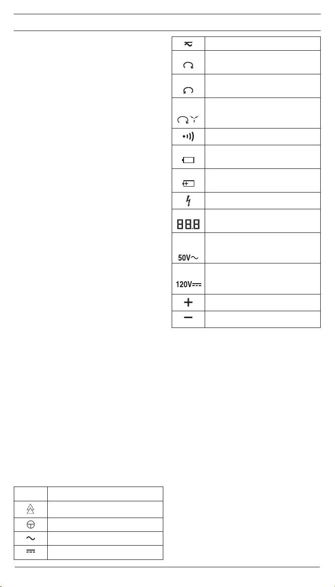
Elektrische Symbole auf dem Gerät:
Symbol Bedeutung
Gerät oder Ausrüstung zum Arbeiten
unter Spannung
Drucktaster
Wechselstrom
Gleichstrom
Gleich- und Wechselstrom
Rechtsdrehsinn, Drehfeldrichtungsan-
zeige (im Display)
Linksdrehsinn, Drehfeldrichtungsanzeige
(im Display)
Drehfeldrichtungsanzeige; die Dreh-
feldrichtung kann nur bei 50 bzw. 60 Hz
und in einem geerdeten Netz angezeigt
werden
Durchgangsprüfung
Batteriesymbol, dieses Symbol erscheint
im Display bei schwacher Batterie
Dieses Symbol zeigt die Ausrichtung der
Batterien zum polrichtigen Einlegen an
Symbol für Phasenanzeige
(im Display)
Spannungswert als Digitalanzeige, bis ca.
80 V mit Dezimalstelle (1/10 V)
Symbol für die Überschreitung des oberen
Grenzwertes für Kleinspannungen (ELV)
bei Wechselspannung (im Display)
Symbol für die Überschreitung des oberen
Grenzwertes für Kleinspannungen (ELV)
bei Gleichspannung (im Display)
Pluspolarität (im Display)
Minuspolarität (im Display)
2. Funktionsbeschreibung
Der DUSPOL®digital LC ist ein zweipoliger Spannungs-
prüfer nach IEC 61243-3 mit Digital-Anzeige. Als Ergän-
zungseinrichtung beinhaltet der Spannungsprüfer eine
Messstellen- und Display-Beleuchtung, eine Phasen- und
Drehfeldrichtungs-Anzeige sowie eine Durchgangsprüf-
einrichtung. Die Signalisierung bei der Durchgangsprü-
fung erfolgt optisch und akustisch. Für alle diese Funk-
tionen benötigt der Spannungsprüfer eine eingebaute
Batterie (2 x Micro LR03/ AAA). Ab einer Spannung von
≥50 V ist eine Spannungsprüfung ohne Batterie möglich.
Die Ermittlung der Phase von Außenleitern und die Dreh-
feldrichtung eines Drehstromnetzes ist nur möglich, wenn
der Sternpunkt geerdet ist.
Das Gerät ist für Gleich- und Wechselspannungsprü-
fungen im Spannungsbereich von 6 V bis AC 690 V/ DC
750 V ausgelegt. Es lassen sich mit diesem Gerät bei
Gleichspannung Polaritätsprüfungen vornehmen.
Der Spannungsprüfer besteht aus den Prüftastern L1
Aund L2 Bund einem Verbindungskabel . Der Prüf-
taster L1 Abesitzt als Anzeigefeld ein LCD-Display 4
sowie kontrastreiche Leuchtdioden 3. Ab einer Span-
nung von 6 V schaltet sich das Gerät selbsttätig ein. Die
vollständige Funktion des Spannungsprüfers ist nur bei
eingelegter und intakter Batterie (im Prüftaster L1 A)
gegeben. Es werden Spannungen im Nennspannungs-
bereich von 6 V bis AC 690 V/ DC 750 V im Display 4
angezeigt. Das Überschreiten des Grenzwertes für Klein-
spannungen (ELV, AC 50 V, DC 120 V) wird im Display
zusätzlich angezeigt.
Beide Prüftaster sind mit Drucktastern Nversehen. Bei
Betätigung beider Drucktaster wird auf einen geringe-
ren Innenwiderstand geschaltet (Unterdrückung von
induktiven und kapazitiven Spannungen). Hierbei wird
nun auch ein Vibrationsmotor (Motor mit Unwucht) an
Spannung gelegt. Ab ca. 200 V wird dieser in Drehbe-
wegung gesetzt. Mit steigender Spannung erhöht sich
auch dessen Drehzahl und Vibration, so dass über die
Handhabe des Prüftasters L2 Bzusätzlich eine grobe
Einschätzung der Spannungshöhe gemacht werden kann
(z.B. 230/ 400 V). Die Dauer der Prüfung mit geringerem
Geräteinnenwiderstand (Lastprüfung) ist abhängig von

12/ 2008
DUSPOL
®
digital LC
4
D D
der Höhe der zu messenden Spannung. Damit das Gerät
sich nicht unzulässig erwärmt, ist ein thermischer Schutz
(Rückregelung) vorgesehen. Bei dieser Rückregelung
fällt auch die Drehzahl des Vibrationsmotors.
Das Anzeigefeld
Das Anzeigefeld besteht aus einem LCD-Display
4sowie kontrastreichen Leuchtdioden (LED) 3, die
Gleich- und Wechselspannungen in Stufen von 12; 24;
50; 120; 230; 400; 690 V anzeigen. Bei den angegebe-
nen Spannungen handelt es sich um Nennspannungen.
Im LCD-Display werden die Überschreitung des oberen
Grenzwertes für Kleinspannungen (ELV) 5, die Phase
6, das Symbol für Durchgang 7, die Drehfeldrichtung 8
und 9, der genaue Spannungswert J, die Polarität bei
Gleichstrom Kund Lsowie ein Symbol für zu schwache
Batterien Mangezeigt. Der Messbereich für die stufen-
lose Spannungsmessung wird automatisch eingestellt.
Bis 80 V wird der Wert mit einer Dezimalstelle angezeigt,
bei größeren Werten entfällt die Dezimalstelle.
2.1 Messstellenbeleuchtung
Die Messstellenbeleuchtung wird durch Betätigung des
Drucktasters Nim Prüftaster L1 Abei eingeschaltetem
Gerät aktiviert. Es erfolgt je nach Helligkeit eine automa-
tische Zuschaltung der LCD-Hintergrundbeleuchtung.
Hinweis:
Für die Messstellenbeleuchtung muss die Anzeige 0,0 V
sein, sonst erkennt der Spannungsprüfer die Hold-Funk-
tion.
2.2 Hold-Funktion
Wird während einer Spannungsprüfung der Drucktaster
N im Prüftaster L1 A1,5 Sekunden betätigt und gehal-
ten, so wird der letzte Messwert blinkend angezeigt. Der
Spannungsprüfer kann vom Anlagenteil getrennt und
abgelesen werden (DATA HOLD). Löschung erfolgt durch
Loslassen des Drucktasters.
Hinweis:
Bei der Lastprüfung, länger als 1,5 Sekunden betätigt,
wird die Hold-Funktion aktiviert!
3. Funktionsprüfung
- Unmittelbar vor dem Benutzen den Spannungsprüfer
auf Funktion prüfen!
- Aktivierung der Prüfeinrichtung (Selbsttest)
• Prüfspitzen kurzschließen
•
Spannungsprüfer über den Drucktaster im Prüf-
taster L1 Aeinschalten und gedrückt halten
• der Summer ertönt, alle Segmente der LCD-
Anzeige sowie Hintergrund- und Messstellenbe-
leuchtung müssen Funktion zeigen
- Testen Sie alle Funktionen an bekannten Spannungs-
quellen.
• Verwenden Sie für die Gleichspannungsprüfung
z.B. eine Autobatterie.
• Verwenden Sie für die Wechselspannungsprü-
fung z.B. eine 230 V-Steckdose.
• Verbinden Sie beide Prüfelektroden zur Funk-
tionskontrolle der Durchgangsprüfung
• Wenn nötig, wechseln Sie die Batterien
Verwenden Sie den Spannungsprüfer nicht, wenn nicht
alle Funktionen einwandfrei funktionieren!
4. So prüfen Sie Wechselspannungen
-Legen Sie die Kontaktelektroden der Prüftaster L1
Aund L2 Ban die zu prüfenden Anlagenteile.
- Der Spannungsprüfer schaltet sich bei vorhandener
Messspannung (6 V) selbsttätig ein und zeigt im
Display den Spannungswert an (bis ca. 80 V mit
Dezimalstelle!).
- Bei Wechselspannung ab 6 V wird der digitale Span-
nungswert Jsowie das Plus- und Minus-Symbol K
und Lim LCD-Display angezeigt. Darüber hinaus
leuchten alle LED bis zum Stufenwert der anliegen-
den Spannung.
- Bei Betätigung beider Drucktaster Nwird im Prüf-
taster L2 B, ab einer anliegenden Spannung von
ca. 200 V, der Vibrationsmotor in Drehbewegung
gesetzt. Mit steigender Spannung erhöht sich seine
Drehzahl.
Achten Sie unbedingt darauf, dass Sie den Spannungs-
prüfer nur an den isolierten Handhaben der Prüftaster L1
Aund L2 Banfassen, das Anzeigefeld nicht verdecken
und die Kontaktelektroden nicht berühren!
Hinweis:
Die Anzeige auf dem LCD-Display kann durch ungünstige
Lichtverhältnisse beeinträchtigt werden.
4.1 So prüfen Sie die Phase bei Wechsel spannung
- Die Phasenprüfung ist im geerdeten Netz ab 230 V
möglich!
- Umfassen Sie vollflächig beide Handhaben/Griffe A
und Bder Prüftaster L1 und L2 (Ableitstrom für Pha-
senprüfung über Handhabe L1!).
- Schalten Sie den Spannungsprüfer durch kurzes
Betätigen des Drucktasters im Prüftaster L1 Aein
(bleibt ca. 10 Sekunden eingeschaltet!). Bei einge-
schaltetem Gerät zeigt die Anzeige „0,0“!
- Legen Sie die Kontaktelektrode des Prüftasters L1
Aan den zu prüfenden Anlagenteil.
Achten Sie unbedingt darauf, dass bei der einpoligen
Prüfung (Phasenprüfung) die Kontaktelektrode vom Prüf-
taster L2 Bnicht berührt wird!
Wenn oben im Display der LCD-Anzeige 4das Symbol
„“ 6erscheint, liegt an diesem Anlagenteil die Phase
einer Wechselspannung.
Hinweis:
Die Anzeige auf dem LCD-Display 4kann durch ungüns-
tige Lichtverhältnisse, Schutzkleidung und isolierende
Standortgegebenheiten beeinträchtigt werden.
5. So prüfen Sie Gleichspannungen
- Legen Sie die Kontaktelektroden der Prüftaster L1
Aund L2 Ban die zu prüfenden Anlagenteile.
- Bei einer anliegenden Spannung von mindestens 6 V
schaltet sich der Spannungsprüfer selbsttätig ein und
zeigt im Display den Spannungswert an.
- Bei Spannungsprüfungen unter 6 V ist der Span-
nungsprüfer durch kurzes Betätigen des Drucktaster
im Prüftaster L1 Aeinzuschalten.
- Bei Gleichspannung ab 6 V wird der digitale Span-
nungswert Jsowie das Plus- oder Minus-Symbol K
und Lim LCD-Display angezeigt. Darüber hinaus
leuchten alle LED bis zum Stufenwert der anliegen-
den Spannung.
-Bei Betätigung beider Drucktaster wird im Prüf-
taster L2 B, ab einer anliegenden Spannung von
ca. 200 V, der Vibrationsmotor in Drehbewegung
gesetzt. Mit steigender Spannung erhöht sich seine
Drehzahl.
5.1 So prüfen Sie die Polarität bei Gleichspannung
- Legen Sie die Kontaktelektroden der Prüftaster L1
Aund L2 Ban die zu prüfenden Anlagenteile.
- Bei einer anliegenden Spannung von mindestens 6 V
schaltet sich der Spannungsprüfer selbsttätig ein und
zeigt im Display den Spannungswert an.
- Bei Spannungsprüfungen unter 6 V ist der Span-
nungsprüfer durch kurzes Betätigen des Drucktaster
im Prüftaster L2 Beinzuschalten.
- Durch ein „+“ Kbzw. ein „–“ Symbol Lwird die
Polarität der anliegenden Gleichspannung angezeigt.
Dabei entspricht der angezeigte Pol dem, der am
Anzeigegriff L1 Aanliegt.
6. So prüfen Sie die Drehfeldrichtung eines Dreh-
stromnetzes
- Die Prüfung der Drehfeldrichtung ist ab 230 V Wech-
selspannung (Phase gegen Phase) im geerdeten
Drehstromnetz möglich.
- Umfassen Sie vollflächig beide Handhaben/ Griffe
12/ 2008
DUSPOL
®
digital LC
5
D D
Aund Bder Prüftaster L1 und L2 (Ableitstrom für
Prüfung der Drehfeldrichtung über Handhabe L1!).
- Legen Sie die Kontaktelektroden der Prüftaster L1
Aund L2 Ban die zu prüfenden Anlageteile.
- Bei einer anliegenden Spannung von mindestens 6 V
schaltet sich der Spannungsprüfer selbsttätig ein und
zeigt im Display den Spannungswert an.
- Die 3-stellige Ziffernanzeige muss die Außenleiter-
spannung anzeigen.
- Bei Kontaktierung der beiden Prüfelektroden an
zwei in Rechtsdrehfolge angeschlossenen Phasen
eines Drehstromnetzes wird im LCD-Display 4 das
Symbol „ “ (Rechtsdrehsinn) 9angezeigt. Ist bei
zwei Phasen die Rechtsdrehfolge nicht gegeben, so
wird das Symbol „ “ (Linksdrehsinn) 8 angezeigt.
Die Prüfung der Drehfeldrichtung erfordert stets eine
Gegenkontrolle! Bei der Gegenkontrolle ist die Messung
mit vertauschten Prüfelektroden nochmals durchzu-
führen. Bei der Gegenkontrolle muss im LCD-Display
ein gegenteiliger Drehsinn angezeigt werden. Zeigt das
Gerät in beiden fällen Rechtsdrehsinn an, liegt eine zu
schwache Erdung vor.
Hinweis:
Die Anzeige auf dem LCD-Display 4kann durch ungüns-
tige Lichtverhältnisse, Schutzkleidung und isolierende
Standortgegebenheiten beeinträchtigt werden.
7. So prüfen Sie eine elektrisch leitende Verbindung
(Durchgangsprüfung)
- Die Durchgangsprüfung ist an spannungsfrei
geschalteten Anlagenteilen durchzuführen, ggf. sind
Kondensatoren zu entladen.
- Die benötigte Prüfspannung liefert die im Prüftas-
ter L1 Aintegrierte Spannungsversorgung (2 x
1,5 V-Batterie).
- Eine Prüfung ist im Bereich von 0 - 200 kΩ möglich.
-
Legen Sie die Prüftaster L1 Aund L2 Bmit den Kon-
taktelektroden an die zu prüfenden Anlagenteile.
- Bei Kontaktierung einer elektrisch leitenden Verbin-
dung mit den Kontaktelektroden ertönt ein Signal-
ton und in der LCD-Anzeige 4wird das Symbol 7
angezeigt.
-
Liegt an der Messstelle Spannung an, schaltet der
Spannungsprüfer automatisch auf Spannungsprüfung
um und zeigt diese an (siehe Abschnitt 4. und 5.).
8. Batteriewechsel
Gerät bei offenem Batteriefach nicht an Spannung legen!
Die Energieversorgung des DUSPOL®digital LC
erfolgt über zwei im Gerät eingebaute Batterien
Typ Micro (LR03/ AAA). Der Batteriewechsel ist
erforderlich, wenn im Display das Batteriesymbol
„“ (schwache Batterie) Merscheint. Dieses erfolgt,
wenn die Batteriespannung unter 2,75 V liegt.
Anzeige der Batteriespannung
Spannungsprüfer durch kurzes Betätigen des Drucktaster
im Prüftaster L1 Aeinschalten, nach ca. 10 Sekunden
wird der Wert der Batteriespannung für 1 Sekunde ange-
zeigt (Beispiel: ).
So wechseln Sie die Batterien:
Entriegeln Sie mit Hilfe eines Schraubendrehers das
Batteriefach (neben dem Kabelaustritt) durch eine
¼-Umdrehung in Pfeilrichtung (gegen den Uhrzeiger-
sinn). Schlitz steht nun senkrecht und das Batteriefach
kann mit den Batterien herausgezogen werden.
Entfernen Sie die entladenen Batterien aus dem Batterie-
fach. Legen Sie die neuen Batterien polrichtig (siehe Auf-
schrift) in das Batteriefach. Schieben Sie das Batteriefach
mit den Batterien wieder in den Schacht und verriegeln
dieses durch eine ¼-Drehung im Uhrzeigersinn (Schlitz
waagerecht und Markierungspunkte stehen gegenüber!).
Achten Sie darauf, dass der O-Ring (T-Nr. 772897) nicht
beschädigt ist, gegebenenfalls ist dieser zu ersetzen.
Batterie-Entsorgung
Batterien gehören nicht in den Hausmüll. Sie können
Ihre alten Batterien bei den öffentlichen Sammelstellen in
Ihrer Gemeinde oder überall dort abgeben, wo Batterien
der betreffenden Art verkauft werden.
9. Technische Daten
- Vorschrift: IEC 61243-3
-
Überspannungskategorie: CAT IV 500 V, CAT III 690 V
-
Schutzart: IP 64 (DIN VDE 0470-1 IEC/ EN 60529)
6 - erste Kennziffer: Schutz gegen Zugang zu gefähr-
lichen Teilen und Schutz gegen feste Fremdkörper,
staubdicht
4 - zweite Kennziffer: Geschützt gegen Spritzwasser.
Auch bei Niederschlägen verwendbar.
- Nennspannungsbereich: 6 V bis AC 690 V/ DC 750 V
- Innenwiderstand, Messkreis: PTC 15 kΩ ≥ 360 kΩ
- Innenwiderstand, Lastkkreis - beide Drucktaster
betätigt!: ca. 3,7 k ... (150 k)
-
Stromaufnahme, Messkreis: max. < 3,5 mA (AC/ DC)
- Stromaufnahme, Lastkreis - beide Drucktaster betä-
tigt!: Is 0,2 A (750 V)
- Polaritätsanzeige: LCD Symbol +; –
- Spannungsanzeige, stufenlos 6 - 750 V,
- Spannungsbereich I: bis ca. 80 V (88,8)
- Spannungsbereich II: ab ca. 80 V (888)
- max. Anzeigefehler:
± 2 % vom Endwert Spannungsbereich
20 - 150 Hz Sinus oder DC
ELV Un- 15 %
- Nennfrequenzbereich f: 0 bis 150 Hz
-
Phasen- und Drehfeldrichtungsanzeige: ≥Un230 V,
50/ 60 Hz
- Vibrationsmotor, Anlauf: ≥Un230 V
- Prüfstrom, Durchgangsprüfung: max. 2 μA
- Prüfbereich, Durchgangswiderstand: 0 - 200 kΩ
- Schallpegel akustisches Signal: 55 dB
- max. zulässige Einschaltdauer: ED = 30 s (max. 30
Sekunden), 240 s Pause
- Geräteeinschaltung bei Messspannung: ≥6 V
-
Geräteeinschaltung per Hand: durch Drucktaster L1 A
-
Eingebaute Prüfeinrichtung: Aktivierung durch Druck-
taster L1 Aund Kurzschließen der Kontaktelektroden
- HOLD-Funktion, Aktivierung Tastendruck ≥1,5 s
- Batterie: 2 x Micro, LR03/ AAA (3 V)
- Gewicht: ca. 200 g
- Verbindungsleitungslänge: ca. 900 mm
- Betriebs- und Lagertemperaturbereich: - 10 °C bis
+ 55 °C (Klimakategorie N)
-
Relative Luftfeuchte: 20 % bis 96 % (Klimakategorie N)
- Rückregelzeiten (thermischer Schutz):
Spannung/ Zeit: 230V/ 30 s, 400 V/ 9 s, 750 V/ 2 s
Achtung!
Spannungsprüfer ist bei leerer Batterie nicht funktionsfä-
hig! Ab einer Spannung von ≥50 V ist eine Spannungs-
prüfung ohne Batterie möglich. Entfernen Sie bei längerer
Lagerung die Batterien aus dem Gerät!
10. Allgemeine Wartung
Reinigen Sie das Gehäuse äußerlich mit einem sauberen
trockenen Tuch (Ausnahme spezielle Reinigungstücher).
Falls Elektrolytverunreinigungen oder weiße Ablagerun-
gen im Bereich der Batterie oder des Batteriegehäuses
vorhanden sind, reinigen Sie auch diese mit einem tro-
ckenen Tuch.
11. Umweltschutz
Bitte führen Sie das Gerät am Ende seiner
Lebensdauer den zur Verfügung stehenden
Rückgabe- und Sammelsystemen zu.

12/ 2008
DUSPOL
®
digital LC
6
Operating manual
DUSPOL®digital LC
Before using the voltage tester DUSPOL®digital LC:
Please read the operating manual carefully and
always observe the safety instructions!
List of contents:
1. Safety instructions
2.
Functional description of the voltage tester
2.1 Measuring point illumination
2.2 Hold function
3. Functional test of the voltage tester
4. How to test AC voltages
4.1 How to test the phase at AC voltage
5. How to test DC voltages
5.1 How to test the polarity at DC voltage
6. How to test the phase sequence of a three-phase
mains
7. How to test an electrically conductive connection
(continuity check)
8. Battery replacement, indicating the battery vol-
tage
9. Technical data
10. General maintenance
11. Environmental notice
1. Safety instructions:
- Hold the voltage tester only by the insulated handles
Aand Band do not touch the contact electrodes
(probe tips) !
- Immediately before use: Check the voltage tester for
correct operation! (see chapter 3). The voltage tester
must not be used if one or several display functions
fail or if the voltage tester is not ready to operate
(IEC 61243-3)!
- The voltage tester must be used only within the nomi-
nal voltage range of 6 V up to AC 690 V/ DC 750 V!
- Do not operate the voltage tester with the battery
compartment being open!
- The voltage tester complies with protection class IP
64 and therefore can also be used under wet condi-
tions (designed for outdoor use).
- For testing, firmly grasp the voltage tester by the
handles Aand B.
- Never connect the voltage tester to voltage for longer
than 30 seconds (maximum permissible operating
time = 30 s)!
- The voltage tester only operates correctly within the
temperature range of - 10 °C up to + 55 °C at relative
air humidity of 20 % up to 96 %.
- Do not dismantle the voltage tester!
- Please protect the housing of the voltage tester
against contamination and damages!
- Please store the voltage tester under dry conditions.
- To prevent injuries and discharge of the battery, pro-
vide the contact electrodes (probe tips) with the enc-
losed cover after using the voltage tester!
Attention:
After maximum load (i.e. after a measurement of 30
seconds at AC 690 V/ DC 750 V), the voltage tester must
not be used for a duration of 240 seconds!
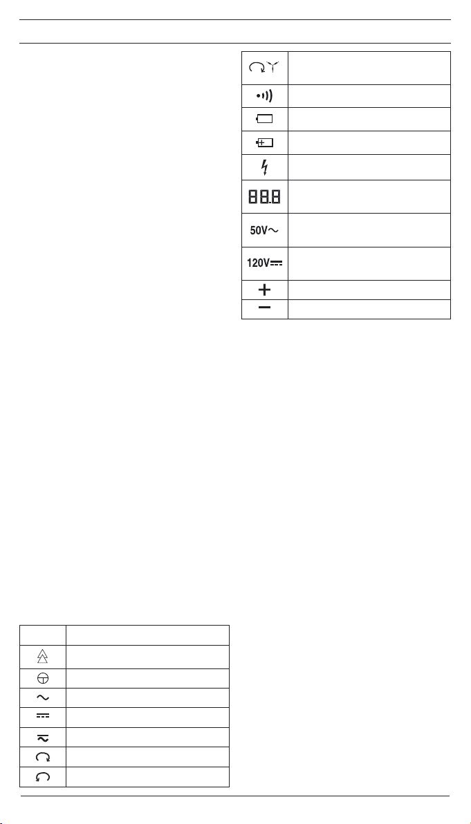
The voltage tester is marked with electric symbols:
symbol meaning
Device or equipment for working under
voltage
Push button
Alternating current (AC)
Direct current (DC)
Direct and alternating current
(DC and AC)
Phase-sequence clockwise, phase-
sequence indication (on the display)
Phase-sequence counter-clockwise,
phase-sequence indication (on the
display)
Phase-sequence indication; the phase
sequence can only be indicated at 50 or
60 Hz and in a earthed mains
Continuity check
Battery symbol, this symbol appears on
the display when the battery is too weak
This symbol shows the correct alignment
of the batteries to ensure correct polarity
Symbol for phase indication (on the
display)
Voltage value as digital indication, up to
approx. 80 V with decimal place (1/ 10 V)
Symbol for exceeding the upper limiting
value for low voltages (ELV) at AC voltage
(on the display)
Symbol for exceeding the upper limiting
value for low voltages (ELV) at DC voltage
(on the display)
Positive (+) polarity (on the display)
Negative (-) polarity (on the display)
2. Functional description
The DUSPOL®digital LC is a two-pole voltage tester
according to IEC 61243-3 with digital display. As supple-
mentary function, the voltage tester is equipped with a
measuring point illumination and display illumination, a
phase and phase-sequence indication as well as con-
tinuity check. The signalling of the continuity check is
done optically and acoustically. For all these functions,
the voltage tester requires a built-in battery (2x micro
LR03/ AAA). Voltage checking without battery is possible
upwards of a voltage of ≥ 50 V. Determining the phase
of external conductors and the phase-sequence of a
three-phase mains is only possible provided the neutral
is earthed.
The voltage tester is designed for DC and AC voltage
tests within the voltage range of 6 V up to AC 690 V/ DC
750 V. It can be used to perform polarity tests at DC vol-
tage.
The voltage tester consists of the test probes L1 Aand
L2 Band a connecting cable . The test probe L1 A
is equipped with a LC display 4as well as high-cont-
rast light-emitting didoes (LED). From a voltage of 6 V
onwards, the voltage tester switches on automatically.
The voltage tester only works properly with the batte-
ries (inside test probe L1 A) being intact and inserted
correctly. The display 4indicates voltages within the
nominal voltage range of 6 V up to AC 690 V/ DC 750 V.
Exceeding the limiting value for low voltages (ELV, AC
50 V, DC 120 V) is additionally indicated on the display.
Both test probes are provided with push buttons . By
pressing both push buttons, the voltage tester switches
to a lower internal resistance (suppression of inductive
and capacitive voltages). Furthermore, a vibrating motor
(motor with a flyweight) is put under voltage. From appro-
ximately 200 V this motor is set in rotation. With the vol-
tage increasing, the motor’s speed and vibration increa-
ses as well so that additionally by means of the handle
of test probe L2 Bthe voltage value can be estimated
roughly (e.g. 230 V/ 400 V). The duration of the test
with a lower internal resistance of the device (load test)

12/ 2008
DUSPOL
®
digital LC
7
depends on the value of the voltage to be measured.
To prevent excessive warming of the voltage tester, it
is equipped with a thermal protection (reverse control).
With this reverse control, the speed of the vibrating motor
decreases as well.
Display field
The display field consist of an LC display 4as well
as high-contrast light-emitting didoes (LED) 3, indicating
DC and AC voltages in steps of 12; 24; 50; 120; 230; 400;
AC 690 V/ DC 750 V. The indicated voltages are nominal
voltages. This LC display indicates the exceeding of the
upper limiting value for low voltages (ELV) 5, the phase
6, the symbol for continuity 7, the phase-sequence 8
and 9, the exact voltage value , the polarity at DC vol-
tage and as well as a symbol for weak batteries .
The measuring range for continuous voltage measure-
ment is set automatically. Up to 80 V, the value is indica-
ted with a decimal place. For higher values, the decimal
place is not indicated.
2.1 Measuring point illumination
The measuring point illumination can be activated by me-
ans of the push button of test probe L1 Awith the de-
vice being switched on. Depending on the brightness, the
LCD background illumination is activated automatically.
Note:
The indication must be 0.0 V for the measuring point
illumination, otherwise the voltage tester identify „Hold“
function.
2.2 Hold function
If you press and hold the push button of test probe L1
A1.5 seconds during a voltage test, the last measuring
value is indicated and is flashing. The voltage tester can
be separated from the unit under test and the measuring
value can be read (DATA-HOLD). The value can be dele-
ted by releasing the push button.
Note:
For load test, press longer than 1.5 seconds, the HOLD
function is activated!
3. Functional check
- Check the voltage tester for correct function immedi-
ately before use!
- Activation of the testing device (self-test),
• short circuit test probes
• switch the voltage tester on by means of the
push button of test probe L1 Aand hold the
push button
• the buzzer sounds, all segments of the LC dis-
play as well as background and measuring point
lighting must indicate function
• after approx. 1 second, the measuring point and
LCD illumination is switched on (test of cable
connection and illumination)
- Test all functions by means of known voltage sour-
ces.
• For DC voltage tests use e.g. a car battery.
• For AC voltage tests use e.g. a 230 V socket.
• Connect both contact electrodes to test the
continuity check for correct function.
• If necessary, replace the batteries.
Do not use the voltage tester unless all functions are
operating correctly!
4. How to test AC voltages
- Place the contact electrodes of the test probes L1
Aand L2 Bagainst the relevant points of the unit
under test.
- If a measuring voltage is present (6 V), the voltage
tester switches on automatically and indicates the
voltage value on the display (up to approx. 80 V
with decimal place!).
- At AC voltage from 6 V onwards, the display indica-
tes the digital voltage value as well as the „plus”
and „minus” symbol and . Furthermore, all
LEDs light until the step value of the applied voltage
is reached.
- When pressing both push buttons and from an
applied voltage of approx. 200 V onwards, a vibrating
motor is put in rotation inside the test probe L2 B.
With the voltage increasing, the speed of this motor
is increasing as well.
Please make sure that you touch the voltage tester at the
insulated handles of test probes L1 Aand L2 Bonly!
Do not cover the display and do not touch the contact
electrodes!
Note:
The reading of the LC display might be impaired due
to unfavorable light conditions.
4.1 How to test the phase at AC voltage
- The phase test is possible in the earthed mains from
230 V onwards!
- Firmly grasp the two handles Aand Bof the test
probes L1 and L2 (leakage current for phase test via
handle L1 A!).
- Switch the voltage tester on by briefly pressing the
push button of test probe L1 A(stays switched
on for approx. 10 seconds). When the device is swit-
ched on, the display indicates „0.0“!
- Place the contact electrode of test probe L1 A
against the relevant point of the unit under test.
Never touch the contact electrode of test probe L2 B
during the single-pole test (phase test)!
If the „ “-symbol 6appears in the upper part of the LC
display 4, the tester is in contact with the live phase of
an AC voltage on this point of the unit under test.
Note:
The reading of the LC display 4might be impaired due
to unfavorable light conditions, protective clothing or in
insulated locations.
5. How to test DC voltages
- Place the contact electrodes of the test
probes L1 Aand L2 Bagainst the relevant points of
the unit under test.
- With an applied voltage of at least 6 V, the voltage
tester switches on automatically and the display indi-
cates the voltage value.
- For voltages tests below 6 V, the voltage tester has to
be switched on by briefly pressing the push button of
test probe L1 A.
- At DC voltage from 6 V onwards, the display indica-
tes the digital voltage value as well as the „plus”
and „minus” symbol and . Furthermore, all
LEDs light until the step value of the applied voltage
is reached.
- When pressing both push buttons and from an
applied voltage of approx. 200 V onwards, a vibrating
motor is put in rotation inside the test probe L2 B.
With the voltage increasing, the speed of this motor
is increasing as well.
5.1 How to test the polarity at DC voltage
- Place the contact electrodes of the test probes L1
Aand L2 Bagainst the relevant points of the unit
under test.
- With an applied voltage of at least 6 V, the voltage
tester switches on automatically and the display indi-
cates the voltage value.
- For voltages tests below 6 V, the voltage tester has to
be switched on by briefly pressing the push button
of test probe L1
A
.
-
The polarity of the applied DC voltage is indicated by
means of a + or a – symbol . Here, the indicated
pole is the pole measures by the indicating handle A.
6. How to test the phase sequence of a three-phase
mains
- The phase-sequence test is possible from 230 V AC
voltage (phase against phase) onwards in a earthed

12/ 2008
DUSPOL
®
digital LC
8
three-phase mains.
- Firmly grasp the insulated handles Aand Bof the
test probes L1 and L2 (leakage current for phase test
via handle L1 A!)
- Place the contact electrodes of the test probes L1
Aand L2 Bagainst the relevant points of the unit
under test.
- With an applied voltage of at least 6 V, the voltage
tester switches on automatically and the display indi-
cates the voltage value.
- The three-digit display has to indicate the voltage of
the external conductor.
- When contacting the two contact electrodes with
two phases of a three-phase mains connected in
clockwise rotation, the LC display 4 indicates the
symbol “ “ (phase-sequence clockwise) 9. If for
two phases the rotation is counter-clockwise, the LC
display indicates the symbol “ “ (phase-sequence
counter-clockwise) 8.
The phase-sequence test always requires a counter-test!
For this purpose, the measurement has to be performed
again with reversed contact electrodes . During the
counter-test, the LC display must indicate the opposite
phase-sequence. If in both cases, the LC display indi-
cates a clockwise phase-sequence, the earthing is too
weak!
Note:
The reading of the LC display 4might be impaired due
to unfavorable light conditions, protective clothing or in
insulated locations.
7. How to test an electrically conductive connection
(continuity check)
- The continuity check must be performed on the rele-
vant points of a “dead” (not being under voltage)
unit under test. If necessary, the capacitors must be
discharged.
- The necessary test voltage is supplied by means of
the power supply (2 x 1.5 V batteries) integrated in
the test probe L1 A.
- The test is possible within the range of 0 - 200 kΩ.
- Place the test probes L1 Aand L2 Bwith the con-
tact electrodes against the relevant points of the
unit under test.
- In the event of contact between an electrically con-
ducting connection and the contact electrodes , a
signal is given off and the symbol 7shown on the
LC display 4.
- If voltage is pending at the measuring point, the vol-
tage checker switches automatically to voltage check
and displays the voltage (see sections 4. and 5.).
8. Battery replacement
Do not set the voltage tester under voltage with the bat-
tery compartment being open!
The energy supply of the DUSPOL®digital LC is done by
means of two built-in micro batteries (LR03/ AAA). Battery
replacement is necessary as soon as the display shows
the battery symbol “ “ (weak battery) . The symbol
appears in case the battery voltage is below 2.75 V.
Indicating the battery voltage
Switch the voltage tester on by briefly pressing the push
button of test probe L1 A. After approx. 10 seconds,
the value of the battery voltage is indicated for 1 second.
(Example: )
How to replace the batteries:
Take a screw driver and open the battery compartment
(next to the cable outlet) by a ¼-turn in direction of the
arrow (counter-clockwise). The slot is now vertical and
the battery compartment with the batteries can be remo-
ved.
Remove the discharged batteries from the battery com-
partment. Insert the new batteries with correct polarity
(see marking) into the battery compartment. Put the bat-
tery compartment with the batteries back onto the handle
and lock it by ¼-turn in clockwise direction (slot must be
horizontal and the marking points are opposite!). Make
sure not to damage the O ring (art.-no. 772897). If neces-
sary, it has to be replaced.
Battery disposal:
Do not dispose of batteries with the household garbage.
You can return used batteries to public collection facilities
in your community area or return them to any retail outlet
selling similar batteries.
9. Technical data:
- Guideline: IEC 61243-3
- Over voltage category: CAT IV 500 V, CAT III 690 V
- Protection class: IP 64, IEC 60529 (DIN 40050)
IP 64 means: Protection against access to dange-
rous parts and protection against solid impurities,
dustproof, (6 - first index). Splash proof, (4 - second
index). Can also be used in case of precipitation.
- Nominal voltage range:
6 V up to AC 690 V/ DC 750 V
- Internal resistance, measuring circuit:
PTC 15 kΩ ≥ 360 kΩ
- Internal resistance, load circuit – both push buttons
actuated!: approx. 3.7 kΩ...(150 kΩ)
- Current consumption, measuring circuit:
max. < 3.5 mA AC/ DC
- Current consumption, load circuit - both push buttons
actuated!: Is 0.2 A (750 V)
- Polarity indication: LCD symbol +; –
- Voltage indication, continuous 6 - 750 V
- Voltage range I: up to approx. 80.0 V (88.8)
- Voltage range II from approx. 80 V (888) onwards
- max. indicating errors:
± 2 % of Voltage range
20 - 150 Hz sinusoidal or DC, ELV Un- 15 %
- Nominal frequency range f: 0 up to 150 Hz
- Phase and phase-sequence indication: ≥ Un230 V,
50/ 60 Hz
- Vibrating motor, starting: ≥ Un230 V
- Test current, continuity check: max. 2 μA
- Testing range, conducting resistance: 0 - 200 kΩ
- Sound level acoustic signal: 55 dB
- max. permissible operating time: ED = 30 s (max. 30
seconds), 240 s pause
-
Device switch-on at measuring voltage: ≥ 6 V
- Device switch-on (manual): by means of push button
L1 A
- Built-in testing function: activation by push button L1
Aand short-circuit of the contact electrodes
- HOLD function, activation press button ≥1.5 s
- Battery: 2 x micro, LR03/ AAA (3 V)
- Weight: approx. 200 g
- Connecting cable length: approx. 900 mm
- Operating and storing temperature range:
- 10 °C up to + 55 °C (climate category N)
- Relative air humidity: 20 % up to 96 % (climate cate-
gory N)
- Reverse control times (thermal protection):
voltage/ time: 230 V/ 30 s, 400 V/ 9 s, 750 V/ 2 s
Attention!
The voltage tester cannot be operated with the batteries
being empty! Voltage checking without battery is possi-
ble upwards of a voltage of ≥ 50 V. Remove the batteries
from the device at a longer storage!
10. General maintenance:
Clean the exterior of the housing with a clean dry cloth
(exception: special cleansing cloths).
Should such electrolyte contamination or white deposits
occur near the battery or the battery housing, these must
also be removed with a dry cloth.
11. Environmental notice
At the end of the product’s useful life, please
dispose of it at appropriate collection points
provided in your country.
12/ 2008
DUSPOL
®
digital LC
9
F F
Mode d’emploi
DUSPOL®digital LC
Avant d‘utiliser le détecteur de tension DUSPOL®
digital LC: lire attentivement le mode d‘emploi et res-
pecter les consignes de sécurité!
Table des matières:
1. Consignes de sécurité
2. Description fonctionnelle du détecteur de ten-
sion
2.1 Eclairage du point de mesure
2.2 Fonction „HOLD“
3. Test de fonctionnement du détecteur de tension
4. Test de tensions alternatives
4.1 Test de la phase de tension alternative
5. Test de tensions continues
5.1 Test de la polarité de tension continue
6. Test de l’ordre de phases d’un réseau triphasé
7. Test d’une connexion conductrice (test de conti-
nuité)
8. Remplacement des piles, indication de la tension
de piles
9. Caractéristiques techniques
10. Entretien général
11. Information sur l’environnement
1. Consignes de sécurité:
- Ne tenir l’appareil que par les poignées isolées Aet
Bsans toucher les électrodes de contact (pointes de
test) !
- Juste avant d’utiliser l’appareil, vérifier son fonction-
nement (voir chapitre 3). Ne pas utiliser l’appareil si
l’une des fonctions d’affichage ne fonctionne pas ou
si l’appareil n’est pas «prêt à l’emploi» (IEC 61243-
3)!
- N‘utiliser le détecteur de tension que dans la gamme
de tension nominale de 6 V à AC 690 V/ DC 750 V!
- Ne pas mettre l‘appareil sous tension quand le com-
partiment des piles est ouvert.
- L’appareil est conform à la classe de protection IP 64
et de là peut être aussi utilisé dans les conditions hu-
mides (construction pour utilisation extérieure).
- Pour le test, tenir l’appareil fermement par les poi-
gnées Aet B.
- Ne jamais mettre l’appareil sous tension pendant plus
de 30 secondes (durée maximale autorisée de mise
sous tension ED = 30 s)!
- L’appareil ne fonctionne correctement que dans une
gamme de température de - 10 °C à + 55 °C dans
une humidité relative de l’air de 20 % à 96 %.
- Ne jamais démonter l‘appareil!
- Veiller à ce que la surface du boîtier de l’appareil ne
soit pas contaminé ou endommagé.
- A préserver de l’humidité.
- Pour éviter des blessures ou un déchargement des
piles, couvrir les électrodes de contact (pointes de
test) avec le revêtement ci-inclus après l’utilisation de
l’appareil!
Attention:
Après une charge maximale (c‘est-à-dire après une me-
sure de 30 secondes à AC 690 V/ DC 750 V) observer
un temps de repos de 240 secondes avant de réutiliser
l‘appareil!
L‘appareil montre les symboles électriques:
symbole signification
appareil ou équipement pour travailler
sous tension
touche
courant alternatif
courant continu
courant continu et alternatif
ordre de phases dans le sens horaire,
indication de l’ordre de phases (sur l’écran
à cristaux liquides)
ordre de phases dans le sens anti-horaire,
indication de l’ordre de phases (sur l’écran
à cristaux liquides)
indication de l‘ordre de phases; l‘ordre
de phase ne peut être indiqué qu‘à 50 ou
60 Hz et dans un réseau triphasé mis à
la terre
test de continuité
symbole de piles, ce symbole apparaît sur
l‘écran à cristaux liquides en cas d‘une pile
trop faible
ce symbole montre l‘orientation correcte
des piles pour une insertion à polarité
correcte
symbole pour l‘indication de la phase (sur
l‘écran à cristaux liquides)
valeur de tension comme affichage
numérique, jusqu‘à environ 80 V avec
décimale (1/10 V)
symbole pour le dépassement de la
valeur limite supérieure pour les tensions
minimales (ELV) en tension alternative
(sur l‘écran à cristaux liquides)
symbole pour le dépassement de la
valeur limite supérieure pour les tensions
minimales (ELV) en tension continue (sur
l‘écran à cristaux liquides)
polarité positive (sur l‘écran à cristaux
liquides)
polarité négative (sur l‘écran à cristaux
liquides)
2. Description fonctionnelle
Le DUSPOL®digital LC est un détecteur de tension bi-
polaire conforme à la norme IEC 61243-3 à affichage nu-
mérique. Comme dispositif complémentaire le détecteur
de tension dispose d‘un éclairage de point de mesure et
de l‘écran à cristaux liquides ainsi qu‘une indication de la
phase et de l‘ordre de phases et d’un dispositif pour le
test de continuité. La signalisation du test de continuité se
produit de manière visuelle et acoustique. Pour toutes ces
fonctions, l’appareil est alimenté par deux piles miniatures
intégrées (2 x micro LR03/ AAA). A partir d’une tension
de ≥ 50 V, un contrôle de tension sans pile est possible.
La détection de la phase de conducteurs externes et la
détection de l’ordre de phases d’un réseau triphasé ne
sont possibles que sous condition de mise à la terre du
neutre.
L‘appareil est destiné à tests de tensions continues et
alternatives de 6 V à AC 690 V/ DC 750 V et peut éga-
lement être utilisé pour des tests de polarité en tension
continue.
L‘appareil comporte les palpeurs de test L1 Aet L2 B
ainsi qu‘un câble de connexion . Le palpeur de test L1
Adispose d‘un écran à cristaux liquides (LCD) 4et dio-
des électroluminescentes (LED) 3à grand contraste. À
partir d’une tension de 6 V l’appareil se branche automa-
tiquement. L’appareil ne fonctionne de manière correcte
qu’avec les piles étant en bon état et insérées correcte-
ment (dans le palpeur de test L1 A). Les tensions dans la
gamme de tensions nominales de 6 V à AC 690 V/ DC
750 V sont indiquées sur l’écran à cristaux liquides 4.
En plus, le dépassement de la valeur limite pour les ten-
sions minimales (ELV, AC 50 V, DC 120 V) est indiqué
sur l’écran.

12/ 2008
DUSPOL
®
digital LC
10
F F
Les deux palpeurs de test disposent de touches . En
actionnant les deux touches en même temps, l‘appareil
commute à une résistance interne plus basse (suppres-
sion de tensions inductives et capacitives). En plus, un
moteur vibratoire (moteur déséquilibré) est activé. A partir
d‘environ 200 V ce moteur est mis en rotation. Avec la
tension augmentante, la vitesse et la vibration du moteur
augmentent aussi. Ainsi, via la poignée du palpeur de
test L2 B, on peut faire une estimation approximative
de la valeur de tension (p.ex. 230/ 400 V). La durée du
test à la résistance interne diminuée (test en charge)
dépend de l‘hauteur de la tension à mesurer. Pour évi-
ter un échauffement excessif de l‘appareil, il dispose
d‘une protection thermique (commande à l‘inverse). Avec
cette commande, la vitesse du moteur vibratoire diminue
aussi.
Fenêtre d‘affichage
La fenêtre d’affichage comporte un écran à cristaux
liquides (LCD) 4et diodes électroluminescentes (LED)
(3) à grand contraste indiquant les tension continues et
alternatives par degrés de 12; 24; 50; 120; 230; 400; AC
690 V/ DC 750 V. Les tension indiquées sont des tension
nominales. Cet écran à cristaux liquides (LCD) indique le
dépassement de la valeur limite supérieure pour les ten-
sions minimales (ELV) 5, la phase, le symbole pour le
continuité 7, l’ordre de phases 8et 9, la valeur exacte
de tension , la polarité en courant continu et ainsi
qu’un symbole pour des piles trop faibles . La plage de
mesure pour une mesure continue de tension est ajustée
automatiquement. Jusqu’à 80 V la valeur est indiquée
avec une décimale. Pour des valeurs plus hautes, la
décimale est supprimée.
2.1 L’éclairage de point de mesure
L’éclairage de point de mesure peut être activé en action-
nant la touche du palpeur de test L1 A avec l’appareil
étant branché. L’éclairage de l’écran à cristaux liquides
est activé automatiquement selon la clarté.
Note :
Pour l‘éclairage du point de mesure, 0,0 V doit être affi-
ché. Sinon, le détecteur de tension ne reconnaît pas la
fonction HOLD.
2.2 Fonction „HOLD“
Si, pendant le test de tension, la touche du palpeur de
test L1 A1,5 secondes est actionnée et tenue, l’écran
à cristaux liquides indique la dernière valeur de mesure
de manière clignotante. L’appareil de mesure peut être
séparé de l’unité à tester et la valeur de mesure peut être
lue (DATA-HOLD). Pour supprimer les valeurs de mesure
lâcher la touche.
Note :
La fonction HOLD est activée si le test de charge est
actionné pour une durée supérieure à 1,5 secondes !
3. Test de fonctionnement
- Juste avant d‘utiliser l‘appareil, vérifier son fonction-
nement!
- Activation du dispositif d‘auto-test
• Court-circuiter les pointes d’essai
• Mettre en marche l‘appareil en actionnant la
touche du palpeur de test L1 Aet maintenir la
pression sur la touche,
• Le vibreur sonore retentit, tous les segments de
l’affichage LCD ainsi que l’éclairage de fond et
des points de mesure doivent fonctionner
- Vérifier toutes les fonctions à partir de sources de
tension connues.
• Pour le test de tension continue utiliser p.ex. un
accumulateur de voiture.
• Pour le test de tension alternative utiliser p.ex.
une prise de courant de 230 V.
• Mettre en contact les deux électrodes de test
pour vérifier le fonctionnement du test de conti-
nuité.
• Si nécessaire, remplacer les piles.
Ne jamais utiliser l‘appareil si une ou plusieures de ses
fonctions ne fonctionnent pas correctement!
4. Test de tensions alternatives
- Mettre les électrodes de contact des palpeurs de
test L1 Aet L2 Ben contact avec les points de me-
sure du dispositif à tester.
- Si une tension de mesure (6 V) est appliquée, l‘appa-
reil se branche automatiquement et l‘écran indique la
valeur de tension (jusqu‘à environ 80 V avec déci-
male!).
- En tension alternative à partir de 6 V, l‘écran montre
la valeur de tension et les symboles «+» et «-»
et . En plus, toutes les LED s’allument jusqu’à la
valeur de degré de la tension appliquée.
- En actionnant les deux touches 3en même temps
et à partir d‘une tension appliquée d‘environ 200 V,
le moteur vibratoire dans le palpeur de test L2 Best
mis en rotation. Avec la tension augmentant, sa vi-
tesse augmente aussi.
Il est essentiel de ne pas tenir l‘appareil que par les poi-
gnées isolées des palpeurs de test L1 Aet L2 B, de ne
pas couvrir la fenêtre d‘affichage et de ne pas toucher les
électrodes de contact!
Attention:
Les indications affichées sur l’écran à cristaux liquides
peuvent être affectées par des conditions d’éclairage
défavorables.
4.1 Test de la phase de tension alternative
- Le test de phase n‘est possible que dans un réseau
mis à la terre et à partir de 230 V!
- Tenir fermement les deux poignées Aet Bdes pal-
peurs de test L1 et L2 (courant de fuite pour le test de
phase via la poignée L1!).
- Mettre l’appareil en marche en actionnant brièvement
la touche du palpeur de test L1 A(reste mis en
marche pour environ 10 secondes). Avec l’appareil
mis en marche, l’écran à cristaux liquides indique
„0,0“!
- Mettre l‘électrode de contact du palpeur de test L2
Ben contact avec le point de mesure du dispositif à
tester.
Ne jamais toucher l‘électrode de contact du palpeur de
test L2 Bpendant le test unipolaire (test de phase)!
Si en haut de l‘écran à cristaux liquides 4le symbole “ “
6apparaît, l‘appareil est en contact avec la phase active
d‘une tension alternative.
Attention:
Les indications affichées sur l’écran à cristaux liquides
4peuvent être affectées par des conditions d’éclairage
défavorables, par des vêtements protectifs ou par des
conditions d’environnement isolantes.
5. Test de tensions directes
- Mettre les électrodes de contact des palpeurs de
test L1 Aet L2 Ben contact avec les points de me-
sure du dispositif à tester.
- À partir d’une tension d’au moins 6 V l’appareil se
branche automatiquement et l’écran à cristaux liqui-
des indique la valeur de tension.
- Pour des tests de tension inférieurs à 6 V, mettre en
marche l‘appareil en actionnant brièvement la touche
du palpeur de test L1 A.
- En tension directe à partir de 6 V, l‘écran montre la
valeur de tension et les symboles «+» et «-»
et . En plus, toutes les LED s’allument jusqu’à la
valeur de degré de la tension appliquée.
- En actionnant les deux touches en même temps
et à partir d‘une tension appliquée d‘environ 200 V,
le moteur vibratoire dans le palpeur de test L2 Best
mis en rotation. Avec la tension augmentant, sa vi-
tesse augmente aussi.
5.1 Test de la polarité de tension directe
- Mettre les électrodes de contact des palpeurs de

12/ 2008
DUSPOL
®
digital LC
11
F F
test L1 Aet L2 Ben contact avec les points de me-
sure du dispositif à tester.
- À partir d‘une tension d‘au moins 6 V l‘appareil se
branche automatiquement et l‘écran à cristaux liqui-
des indique la valeur de tension.
- Pour des tests de tension inférieurs à 6 V, mettre en
marche l‘appareil en actionnant brièvement la touche
du palpeur de test L2 B.
- La polarité de la tension continue appliquée est indi-
quée par les symboles «+» ou «-» . La polarité
indiquée est la polarité présente à la poignée d‘affi-
chage L1 A.
6. Test de l‘ordre de phases d‘un réseau triphasé
- Le test de l‘ordre de phases est possible à partir de
230 V de tension alternative (phase contre phase)
dans un réseau triphasé mis à la terre.
- Tenir fermement les poignées isolées Aet Bdes
palpeurs de test L1 et L2 (courant de fuite pour le test
de phase via la poignée L1!).
- Mettre les électrodes de contact des palpeurs de
test L1 Aet L2 Ben contact avec les points de me-
sure du dispositif à tester.
- À partir d‘une tension d‘au moins 6 V l‘appareil se
branche automatiquement et l‘écran à cristaux liqui-
des indique la valeur de tension.
- L‘indication à trois chiffres doit indiquer la tension de
conducteur extérieur.
- Lorsque l‘on met en contact les deux électrodes de
contact avec deux phases d‘un réseau triphasé en
ordre de phase dans le sens horaire, un symbole « »
9(l’ordre de phases dans le sens horaire) apparaît sur
l‘écran à cristaux liquides 4. Au cas où deux phases ne
sont pas dans le sens horaire, l’écran à cristaux liquides
indique le symbole « » 8 (l‘ordre de phases dans le
sens anti-horaire).
Le test de l‘ordre de phases requiert toujours un contre-
test! Pour ce contre-test, vérifier à nouveau les deux pha-
ses en inversant les électrodes de contact . Lors du
contre-test, l‘écran à cristaux liquides doit indiquer l‘ordre
de phases contraire. Si, dans les deux cas, l‘écran indi-
que l‘ordre de phases dans le sens horaire, la misa à la
terre est insuffisante.
Attention:
Les indications affichées sur l’écran à cristaux liquides
4peuvent être affectées par des conditions d’éclairage
défavorables, par des vêtements protectifs ou par des
conditions d’environnement isolantes.
7. Test d’une connexion conductrice (test de conti-
nuité)
- Pour le test de continuité, ne pas mettre le dispositif
à tester sous tension. Si nécessaire, décharger les
condensateurs.
- La tension de test nécessaire est fournie par l’ali-
mentation en courant intégrée dans le palpeur de
test L1 (2 piles à 1,5 V).
- Le test est possible dans la gamme de 0 - 200 kΩ.
- Mettre les électrodes de contact des palpeurs
de test L1 Aet L2 Ben contact avec les points de
mesure du dispositif à tester.
- En cas de mise en contact d’une connexion électri-
que conductrice avec les électrodes de contact ,
une tonalité de signalisation retentit et le symbole 7
est affiché dans l’affichage LCD 4.
- Si le point de mesure est sous tension, le contrôleur
de tension commute automatiquement sur le contrôle
de tension et l’indique (voir paragraphes 4. et 5.).
8. Remplacement des piles
Ne pas mettre l‘appareil sous tension quand le comparti-
ment des piles est ouvert!
Le DUSPOL®digital LC est alimenté par deux piles mi-
niatures incorporées (LR03/ AAA). Le remplacement des
piles est nécessaire quand l’écran à cristaux liquides in-
dique le symbole de piles « » (piles trop faibles) . Ce
symbole apparaît lorsque la tension de piles est inférieure
à 2,75 V.
Indication de la tension de piles
Mettre l‘appareil en marche en actionnant brièvement la
touche du palpeur de test L1 A. Après environ 10 se-
condes, la valeur de la tension de piles est indiquée pour
1 seconde (par exemple : ).
Pour remplacer les piles:
Utiliser un tournevis pour ouvrir le compartiment des piles
(à côté du cable de connexion) par un quart de tour en
direction de la flèche (dans le sens anti-horaire). Main-
tenant, la fente est verticale et le compartiment des piles
peut être retiré avec les piles.
Enlever les piles déchargées du compartiment des piles.
Insérer les nouvelles piles en observant la polarité cor-
recte (voir les symboles) dans le compartiment des piles.
Remettre le compartiment des piles en place et le res-
serrer par un quart de tour dans le sens horaire (la fente
doit être horizontale et les marques sont en face!). Ne
pas endommager la bague O (numéro de pièce 772897).
Remplacer-la, si nécessaire.
Elimination des piles:
Ne jamais jeter les piles à la poubelle. Retourner les piles
usées aux points de collecte publics ou les déposer a un
point de vente de piles.
9. Caractéristiques techniques:
- norme: IEC 61243-3
- catégorie de surtension: CAT IV 500 V, CAT III 690 V
-
classe de protection: IP 64, IEC 60529 (DIN 40050)
IP 64 signifie: protection contre l’accès aux compo-
sants dangereux et protection contre les impuretés
solides, étanche aux poussières, (6 - premier indice).
Étanche au jet d’eau, (4 - second indice). Aussi utili-
sable en cas de précipitations.
- gamme de tensions nominales: 6 V à AC 690 V/ DC
750 V
- résistance interne, circuit de mesure: PTC 15 kΩ ≥
360 kΩ
- résistance interne, circuit de charge - en actionnant
les deux touches!: environ 3,7 kΩ...(150 kΩ)
- consommation de courant, circuit de mesure: max.
< 3,5 mA AC/ DC
- consommation de courant, circuit de charge - en ac-
tionnant les deux touches!: Is0,2 A (750 V)
- affichage de la polarité: LCD symbole +; –
- affichage de tension, en continu 6 - 750 V
- gamme de tension I: jusqu‘à environ 80.0 V (888)
- gamme de tension II: à partir d‘environ 80 V (888)
- max. erreurs d‘affichage:
± 2 %, gamme de tension
20 - 150 Hz sinus / C.D. ELV Un- 15 %
- gamme de fréquences nominales f: 0 à 150 Hz
- affichage de la phase et de l’ordre de phases:
≥ Un230 V, 50/ 60 Hz
- courant de test, test de continuité: max. 2 μA
- plage de test, résistance transversale: 0 - 200 kΩ
- niveau sonore du signal acoustique: 55 dB
- moteur vibratoire, démarrage: ≥ Un230 V
- durée maximale de mise en service: ED = 30 s (max.
30 s) , 240 s pause
- mise en marche de l‘appareil en tension de mesure:
≥ 6 V
- mise en marche de l‘appareil (manuelle): par la tou-
che L1 A
- dispositif de test incorporé: activation par la touche L1
Aet mise en court-circuit des électrodes de contact
- Fonction HOLD, activation en appuyant sur la touche
≥1,5 s
- piles: 2 x micro, LR03/ AAA
- poids: environ 200 g
- câble de connexion: environ 900 mm
- gamme de températures de service et de stockage:
- 10 °C à + 55 °C (catégorie climatique N)
- humidité relative de l’air: 20 % à 96 % (catégorie cli-
matique N)

12/ 2008
DUSPOL
®
digital LC
12
F F
- temps de commande à l’inverse (protection thermi-
que):
tension/ temps: 230 V/ 30 s, 400 V/ 9 s, 750 V/ 2 s
Attention!
Le détecteur de tension ne fonctionne pas avec des piles
vides ! A partir d’une tension de ≥ 50 V, un contrôle de ten-
sion sans pile est possible. Enlevez les piles de l‘appareil
à un plus long stockage !
10. Entretien général
Nettoyer l’extérieur du boîtier avec un chiffon propre et
sec (ou un tissu de nettoyage spécial).
En cas d’apparition de contamination ou de dépôt blanc
près des piles ou dans le boîtier, nettoyer avec un chiffon
sec.
11. Information sur l’environnement
Une fois le produit en fin de vie, veuillez le
déposer dans un point de recyclage approprié.
12/ 2008
DUSPOL
®
digital LC
13
E E
Manual de funcionamiento
DUSPOL®digital LC
Antes de utilizar el medidor DUSPOL® digital LC, por
favor lea el manual atentamente y observe siempre
las instrucciones de seguridad!
Lista de contenido:
1. Instrucciones de seguridad
2. Descripción funcional del medidor
2.1 Iluminación punto de medida
2.2 Función mantenida
3. Prueba funcional del medidor
4. Como medir tensiones alternas (AC)
4.1 Cómo medir la fase en tensiones AC
5. Cómo medir tensiones continuas (DC)
5.1. Cómo medir la polaridad en tensiones DC
6. Cómo medir la secuencia de fase en líneas trifási-
cas
7. Cómo se prueba continuidad
8. Cambio de batería, indicación de tensión de bate-
ría
9. Datos técnicos
10. Mantenimiento general
11. Advertencia
1. Instrucciones de seguridad
- Coger el medidor sólo por las partes aisladas A y B.
No tocar las puntas de medida !
- Antes de utilizarlo: Comprobar el correcto funciona-
miento del medidor (ver apartado 3). El medidor no
debe ser utilizado si una o varias funciones del dis-
play falla o sí el medidor no está listo para funcionar
(IEC 61243-3)!
-
El medidor de tensión debe ser usado sólo cuando el
rango de tensión está entre 6 y 690 V AC/ 750 V DC!
- El medidor cumple con la protección IP64, por lo que
puede ser utilizado en condiciones de humedad (está
diseñado para trabajos en exterior)
- Para medir sujetar fuertemente el medidor por las
partes aisladas A y B
- Nunca conectar el medidor a la medida por más tiem-
po de 30 segundos(máximo tiempo de conexión = 30
segundos)
- El medidor de tensión sólo funciona correctamente
con temperaturas entre - 10 °C y + 55 °C y con hu-
medades del 20 al 96 %
- No desmontar el medidor!
- Proteger la carcasa del medidor contra contamina-
ciones y daños!
- Almacenar el medidor en condiciones secas!
- Proteger las puntas del medidor después de su utili-
zación con la pieza que se envía para evitar acciden-
tes y descarga de baterías.
Atención:
Después de una carga máxima (por ejemplo medida du-
rante 30 segundos en 690 V CA/ 750 V CC), el medidor
no se debe usar hasta pasados 240 segundos!
El medidor está marcado con símbolos eléctricos:
Símbolo Significado
Dispositivo o equipo para trabajar bajo
tensión
Botón pulsador
Corriente alterna AC
Corriente continua CC
Corriente alterna y continua (AC y DC)
Secuencia de fases en sentido horario
Secuencia de fases en sentido antihorario
Indicación secuencia de fases. La
secuencia de fases sólo puede indicarse
en 50 Hz y 60 Hz
Prueba de continuidad
Símbolo de batería, este símbolo aparece
en el dispaly cuando la batería está baja
Este símbolo muestra la correcta polaridad
de las baterías y tensión
Símbolo de indicación de fase (en el
dispaly)
Valor de tensión indicado como digital
hasta 80 V aproximadamente con punto
decimal (1/ 10 V)
Símbolo para indicación del valor límite
de baja tensión (ELV) en tensión AC (en
el display)
Símbolo para indicación del valor límite
de baja tensión (ELV) en tensión DC (en
el display)
Polaridad positiva (+) (en el dispaly)
Polaridad negativa (-) (en el dispaly)
2. Descripción funcional del medidor
El medidor DUSPOL® digital LC es un medidor bipolar de
acuerdo a IEC 61243-3 con visualizador de display. Cómo
función suplementaria, el medidor de tensión y está equi-
pado con una iluminación del punto de medida y ilumina-
ción del display, indicación de fase y de la secuencia de
fase, como tabien prueba de continuidad. La prueba de
continuidad se puede realizar de forma óptica y acústica.
Para todas estas funciones el medidor necesita una ba-
tería interna. (2 micro baterías tipo LR 03/ AAA). A partir
de una tensión ≥ 50 V es posible una comprobación de
tensión sin batería. La determinación de fase en conduc-
tores externos y la secuencia de fase en redes trifásicas
sólo es posible sí el neutro está a tierra. El medidor esta
diseñado para tensiones de AC y DC en valores desde 6
hasta 690 V AC/ 750 V DC. Puede utilizarse para indicar
la polaridad en DC y la secuencia de fases en AC en re-
des con el neutro a tierra.
El medidor posee dos puntas L1 A y L2 By un cable
de conexión . La punta de prueba L1 Aposee un
display 4, como tambien diodos de alta emisión (LED)
3. Desde una tensión de 6 V, el medidor se enciende
automáticamente. El medidor de tensión sólo funciona
correctamente con las baterías (situadas dentro de la
punta L1 A) correctamente cargadas e instaladas. El
display 4indica la tensión en un rango de 6 V hasta
690 V AC/ 750 V DC. Al exceder el límite el valor límite
para tensiones bajas (ELV, AC 50 V, DC 120 V) es indi-
cado adicionalmente en el display.
Ambas puntas de prueba poseen dos botones . AL
presionar ambos botones, el medidor de tensión cambia
a resistencia de interna baja (eliminación de tensiones
inductivas y capacitivas). Además un motor vibratorio
se actúa. Desde 200 V este motor se pone en funcio-
namiento. Cuando la tensión aumenta la vibración del
motor también se incrementa y eso se nota en la punta
de medida L2 B. La duración de la prueba con baja
resistencia del dispositivo depende del valor de la ten-
sión medida. Para prevenir un excesivo peligro del medi-
dor el medidor esta equipado con un dispositivo térmico
de protección (control inverso). Con este control inverso,
la vibración del motor disminuye también.
Rango del display
El display de medida consiste en un display LC 4,
como tambien diodos de alta emisión (LED) 3indicando
tensiones AC y DC en pasos de 12, 24, 50, 120, 230,
400, 690 V AC/ 750 V DC. Las tensiones indicas son no-

12/ 2008
DUSPOL
®
digital LC
14
E E
minales. Este display LC muestra (ELV) para tensiones
altas y bajas 5, la fase 6, el simbolo de continuidad 7la
secuencia de fase 8y 9, el valor exacto , la polaridad
en DC y así como el símbolo de batería baja . EL
rango de medida para continuas es automático a partir de
80 V, el valor es indicado con un decimal. Para valores
superiores no se muestra el decimal.
2.1 Iluminación punto de medida
La iluminación del punto de medida puede actuarse por
medio del botón pulsador de la punta de prueba L1
y se enciende el medidor. Dependiendo de la iluminación,
el fondo del display se ilumina automáticamente.
Nota:
La indicación debe ser 0.0 V para la iluminación del punto
de medida, en otro caso el medidor de tensión identificará
la función “Hold”
2.2 Función mantenida
Sí presiona el botón de la punta de prueba L1 Ay lo
mantenemos durante una medida, el último valor medido
queda parpadeando. El medidor puede separase de la
medida y el valor puede leerse (DATA-HOLD). El valor se
borra al soltar el botón.
Nota:
Para pruebas de carga, presionar más de 1,5 segundos,
la función HOLD se activará!
3. Prueba funcional
- Comprobar el correcto funcionamiento del medidor
justo antes de utilizarlo.
- Activación de prueba de dispositivo (auto prueba)
•Cortocircuitar las puntas de prueba
•Encender el medidor por la presión del botón de
la punta de prueba L1 Ay mantenerlo pulsa-
do.
•Suena el zumbador, todos los segmentos de la
indicación LCD así como la iluminación de fondo
y puntos de medición deben mostrar función
- Probar todas las funciones por medio de fuentes de
tensión conocidas.
•Para tensiones DC use por ejemplo una batería
de coche.
•Para tensiones AC use por ejemplo la tensión de
cualquier enchufe.
• Una ambos electrodos para probar el correcto
funcionamiento de continuidad
•Sí es necesario, cambiar las baterías.
No utilice el medidor si todas las funciones no son co-
rrectas!
4. Como se prueba las tensiones alternas (AC)
- Colocar las puntas de las puntas de prueba sobre
la unidad que se desee probar
- Sí una tensión superior a 6 V está presente en el
punto de medida, el medidor se enciende automáti-
camente y muestra en el display el valor de la tensión
(hasta los 80 V con un decimal).
- En tensiones AC desde 6 V, el display indica el va-
lor de la tensión, como tambien el símbolo más y el
menos y . Además el resto de LED se iluminan
hasta indicar el valor medido.
- Cuando se presionan ambos botones y desde la
aplicación de 200 V, un motor vibra dentro de la pun-
ta de prueba L2 B. Cuando la tensión aumenta, la
velocidad del motor también aumenta.
Asegúrese de que sólo toca la punta de prueba por la
parte aislante L1 A y L2 B! No tapar el display y no tocar
las puntas de los electrodos
Nota:
La lectura del display LC puede ser alterada debido a
desfavorables condiciones de luz.
4.1 Cómo se prueba la fase en tensiones AC
- La prueba de fase es posible en redes de más de
230 V!
- Sujetar firmemente el medidor por las partes aisla-
das A y Bde las puntas L1 y L2 (corriente de fugas
para prueba de fase con punta L1!)
- Encender el medidor pulsando brevemente el botón
de la punta de prueba L1 A(se enciende des-
pués de unos 10 segundos). Cuando se enciende en
el display se muestra "0,0"!
- Poner el punto de prueba de la punta de prueba
Aen el punto que se desea medir.
Nunca tocar el contacto de la punta de prueba L2 Bdu-
rante la prueba de fase en monofásica!
Sí el símbolo “ ” 6se muestra en la parte superior del LC
display 4, el medidor está conectado sobre la fase de la
señal de alterna.
Nota:
La lectura del display LC 4y puede ser imprecisa debido
a condiciones de luz desfavorables, prendas protectoras
o locales aislados.
5. Como medir tensiones continuas
- Poner los electrodos de medida de las puntas de
medida L1 y L2 sobre los puntos a medir.
- Cuando se conecta a medidas de tensión superiores
a 6 V, el medidor se conecta automáticamente y el
display muestra el valor medido.
- Para tensiones inferiores a 6 V el medidor se debe
encender presionando brevemente el botón de la
punta de prueba L1 A
- En tensiones DC desde 6 V, el display indica el va-
lor de la tensión, como tambien el símbolo más y el
menos y . Además el resto de LED se iluminan
hasta indicar el valor medido.
- Cuando se presionan ambos botones y la tensión
aplicada excede los 200 V un motor vibrador se ac-
túa dentro de la punta de prueba L2 B. Al aumentar
la tensión también se incrementa la velocidad de vi-
bración del motor.
5.1 Como se prueba la polaridad en DC
- Poner los electrodos de medida de las puntas de
medida L1 Ay L2 Bsobre los puntos a medir.
- Cuando se conecta a medidas de tensión superiores
a 6 V, el medidor se conecta automáticamente y el
display muestra el valor medido.
- Para tensiones inferiores a 6 V el medidor se debe
encender presionando brevemente el botón de la
punta de prueba L2 B
- La polaridad de la tensión DC aplicada es indicada
por medio de un símbolo ”+” o un “-” . Aquí el
polo indicado es el de la punta L1 A.
6. Cómo medir la secuencia de fase en líneas trifási-
cas
- La secuencia de fase es posible en tensiones desde
230 V AC (fase – fase) en una red trifásica
- Sujetar con firmeza las puntas A y Bde las puntas
de prueba L1 y L2. (corriente de fugas para prueba
de fase con punta L1!).
- Poner los electrodos de medida de las puntas de
medida L1 Ay L2 Bsobre los puntos a medir.
- Sí una tensión superior a 5 V está presente en el
punto de medida, el medidor se enciende automá-
ticamente y muestra en el display el valor de la ten-
sión
- El LC display indica el valor de la tensión por me-
dio de tres dígitos 7.
- Cuando conecte los dos electrodos 1 con dos fases
de una red trifásica está en sentido horario, el display
LC 4 indica el símbolo “ ” 9. Sí dos fases están en
sentido antihorario, el LC display indica el símbolo “
” 8.
La secuencia de fases sólo requiere una medida! Si el
display indica sentido horario para dos fases en una
red trifásica, estas dos fases probadas también con
los electrodos 1 en sentido contrario. En este caso no
se mostrará el símbolo sobre el display 4. Sí en ambos
12/ 2008
DUSPOL
®
digital LC
15
E E
casos se muestra el símbolo esto es indicativo de que la
tierra es muy mala!
Nota:
La lectura del display LC 4 y puede ser imprecisa debido
a condiciones de luz desfavorables, prendas protectoras
o locales aislados.
7. Cómo se prueba continuidad
- La prueba de continuidad se debe realizar sobre
elementos sin tensión. Sí fuese necesario se deben
descargar los condensadores existentes.
- La tensión necesaria para realizar la prueba la sumi-
nistran las dos baterías de 1,5 V integradas en la
punta de prueba L1 A.
- La prueba se puede realizar dentro de un rango de 0
a 200 kΩ.
- Poner las puntas de prueba L1 Ay L2 Bcon los
eléctrodos de contacto sobre los puntos que se
desea medir.
- Al establecerse el contacto de una conexión eléc-
trica con los electrodos de contacto suena una
señal acústica y en la indicación LCD 4se muestra
el símbolo 7.
- Si en el punto de medición existe tensión, el compro-
bador de tensión cambia inmediatamente a compro-
bación de tensión y la muestra (véanse los capítulos
4. y 5.).
8. Cambio de la batería
No tener el medidor sobre tensión cuando la batería se
este reemplazando!
La alimentación del DUSPOL®digital LC se realiza me-
diante dos micro baterías (LR03/ AAA). El cambio de la
batería debe realizarse en cuanto se muestra el símbolo
“ “ . El símbolo aparece cuando la tensión de la ba-
tería es inferior a 2,75 V.
Indicación tensión de batería
Encender el medidor presionando el botón de la punta
de prueba L1 A. Después de 10 segundos aproximada-
mente, el valor de la tensión de la batería se indica duran-
te un segundo (ejemplo )
Cómo se cambian las baterías
Con un destornillador abrir el compartimento de la bate-
ría (cerca del cable de unión).Es un cuarto de vuelta en
sentido antihorario. Poner el compartimento en sentido
vertical y se pueden cambiar las baterías.
Quitar las baterías gastadas e insertar las nuevas bate-
rías con la polaridad correcta. Una vez ubicadas las bate-
rías girar de nuevo un cuarto de vuelta en sentido horario
la tapa del compartimento.
Retirada de baterías
No tire las baterías en la basura normal. Como consumi-
dor está obligado a dejar las baterías usadas en lugares
propios de este tipo de residuos, los cuales suelen estar
disponibles en varios lugares de la ciudad.
9. Datos técnicos
- Normativa IEC 61243-3
- Categoría de sobretensión: CAT IV 500 V, CAT III
690 V
- Clase de protección: IP 64, IEC 60529 (DIN 40050),
también de uso intemperie.
Protección IP 64 significa:
Primer dígito (6): Protección contra contactos a par-
tes peligrosas y contra objetos, protegido contra de
polvo.
Segundo dígito (4): Protegido contra del chapoteo de
agua. Puede ser usado incluso en casos de lluvia.
- Rango de tensiones; desde 6 a 690 V AC/ 750 V
DC.
- Resistencia interna, circuito de medida: PTC 15 kΩ ≥
360 kΩ
- Resistencia interna, circuito de carga- ambos boto-
nes pulsados: aproximadamente 3,7 kΩ... (150 kΩ)
- Corriente absorbida, circuito de medida: máx. <
3,5 mA AC/ DC
- Corriente absorbida, circuito de carga- ambos boto-
nes pulsados: IS 0,2 A (750 V)
- Indicación de polaridad: LCD símbolo + ó –
- Indicación de tensión continua 6 a 750 V
- Rango I de tensión : hasta 80 V (88,8)
- Rango II de tensión : desde 80 V (888)
- Error máximo: ± 2 de los rangos 20 a 150 Hz en se-
noidal o DC ELV Un-15 %
- Rango de frecuencia: 0 a 150 Hz
- Indicación de fase y secuencia de fases: ≥230 V, 50/
60 Hz
- Inicio vibración motor: ≥230 V
- Corriente prueba continuidad: 2 μA máximo
-
Rango de medida, resistencia de continuidad: 0 - 200 kΩ
- Nivel de ruido acústico: 55 dB
- Máximo tiempo de conexión: ED= 30 segundos, 240
segundos de pausa.
- Conexión en tensiones ≥6V
- Encendido manual al pulsar el botón 3 de la punta L1
A
- Función incorporada: activación al pulsar el botón
de la punta de prueba L1 Ay cortocircuitar las pun-
tas de los electrodos.
- La function HOLD, se active presionando el botón
≥1.5 s
- Baterías: 2 MICRO LR03/ AAA
- Peso: 200 gramos aproximadamente
- Longitud del cable de conexión: 900 mm aprox.
- Rango de temperatura de funcionamiento y almace-
namiento: -10 ºC a +55 ºC (categoría climática N)
- Humedad relativa: 20 al 96% (categoría climática N)
- Control inverso temporizado (protección térmica):
Tensión/ tiempo: 230 V/ 30 s, 400 V/ 9 s, 750 V/ 2 s
Atención!
Este medidor no funciona con las baterías descargadas!
A partir de una tensión ≥ 50 V es posible una comproba-
ción de tensión sin batería. Quitar las baterías sí el medi-
dor va a estar sin utilizar un tiempo largo!
10. Mantenimiento general
Limpiar el exterior del medidor con un paño seco y lim-
pio.
Sí se detecta algún líquido en la zona de baterías este
debe limpiarse con un paño seco.
11. Advertencia
Para preservar el medio ambiente, al final de
la vida útil de su producto, deposítelo en los
lugares destinado a ello de acuerdo con la
legislación vigente.

12/ 2008
DUSPOL
®
digital LC
16
Инструкция за експлоатация
на DUSPOL®digital LC
Преди използване на тестера за напрежение
DUSPOL® digital LC: Моля прочетете инструкцията
за експлоатация внимателно и винаги спазвайте
инструкциите за безопасност!
Съдържание:
1. Инструкции за безопасност
2.
Описание на работата на тестера за напрежение
2.1 Осветяване на измервателна точка
2.2 Функция запазване на измерената стойност
3. Тест на работата на тестера за напрежение
4. Как да тестваме променливи AC напрежения
4.1 Как да тестваме фаза на променливо AC
напрежение
5. Как да тестваме постоянни DC напрежения
5.1 Как да тестваме поляритет на постоянни DC
напрежения
6. Как да тестваме фазова последователност на
трифазно захранване
7. Как да тестваме електро проводими съедине-
ния (проверка на непрекъснатост)
8. Подмяна на захранващите батерии, индикация
за волтажа на батериите
9. Технически данни:
10. Основна поддръжка:
11. Защита на околната среда
1. Инструкции за безопасност:
- Дръжте тестера за напрежение само за изолира-
ните ръкохватки Aи B и не докосвайте контакт-
ните елементи (накрайниците на сондите) !
- Непосредствено преди използване: Проверете
тестера за напрежение за правилна работа! (Виж
част 3). Тестера за напрежение не бива да се
използва ако някоя от функциите на дисплея е
повредена или тестера за напрежение не готов за
работа (стандарт IEC 61243-3)!
- Тестера за напрежение трябва да се използва
само в рамките на зададеното номинално напре-
жение от 6 V до AC 690 V/ DC 750 V!
- Не използвайте тестера за напрежение когато
отделението за батерии е отворено!
- Тестера за напрежение покрива изискванията
на степен на защита от проникване на твърди
частици и течности IP 64 и затова може да бъде
използван при влажна среда (разработен е за
използване при открит монтаж).
- При изпитване, дръжте здраво тестера за напре-
жение за ръкохватките Aи B.
- Никога не свързвайте тестера за напрежение към
напрежения за период по-дълъг от 30 секунди
(максимално допустимото работно време = 30 s)!
- Тестера за напрежение работи правилно в темпе-
ратурен обхват от - 10 °C до + 55 °C при относи-
телна влажност на въздуха от 20 % до 96 %.
- Не разглобявайте тестера за напрежение!
- Моля пазете корпуса на тестера за напрежение от
замърсяване и повреди!
- Моля съхранявайте тестера за напрежение при
сухи условия.
- За да предотвратим повреждане и разреждане на
батериите, след използване на тестера покрийте
контактните елементи на измервателните сонди с
предвидените предпазни капачки!
Внимание:
След максимално натоварване (тоест след измерва-
ния за период от 30 секунди при AC 690 V/ DC 750 V),
тестера за напрежение не бива да се използва в про-
дължение на 240 секунди!
Тестера за напрежение има маркировка с електриче-
ски символи:
символ значение
Апарати или съоръжения за работа под
напрежение
Бутон
Променлив ток (AC)
Постоянен ток (DC)
Постоянен и променлив ток (DC and
AC)
Фазова последователност в посока на
въртене на часовниковата стрелка,
индикация за фазова последователност
(на дисплея)
Фазова последователност в посока
обратна на въртене на часовниковата
стрелка, индикация за фазова
последователност (на дисплея)
Индикация за фазова последователност;
фазовата последователност може да
се индицира само при честота 50 или
60 Hz и при заземени вериги.
Проверка на непрекъснатост
Символ батерия, появява се на дисплея
когато батерията е твърде слаба
Този символ показва вярното поставяне
на батериите за да осигурим точното
съединяване на поляритета им.
Символ за индикация на фаза (на
дисплея)
Стойност на напрежението като
цифрова индикация, до приблизително
80V с десетична стойност (1/10 V)
Символ за надхвърляне на горната
граница (ELV) за ниско АС напрежение
(на дисплея)
Символ за надхвърляне на горната
граница (ELV) за ниско DС напрежение
(на дисплея)
Положителен (+) полюс (на дисплея)
Отрицателен (-) полюс (на дисплея)
2. Описание на действието
Тестера DUSPOL® digital LC е двуфазен тестер
за напрежение съобразно стандарт IEC 61243-3 с
цифров дисплей. Като допълнителна функция, тес-
тера за напрежение е екипиран с осветяване на
измервателната точка и осветяване на дисплея, както
и индикация за наличие на фаза и индикация за
фазова последователност и функция за проверка на
наличие на верига. Сигнализацията на проверката за
непрекъснатост е реализирана оптично и акустично.
За всички тези функции, тестера за напрежение
изисква инсталирана батерия (2 x micro LR03/ AAA)
При напрежение от ≥ 50 V е възможно изпитване на
напрежението без батерия. Означаването на фаза на
външни проводници и фазова последователност на
трифазни захранващи вериги е възможно само при
системи с заземен неутрален проводник.
Тестера за напрежение е разработен за тестове на
DC и AC напрежение при обхват на напрежението от
6 V до AC 690 V/ DC 750 V. Той може да бъде използ-
ван за изпълнение на тест за поляритет на DC напре-
жение.
Тестера за напрежение включва изпитателни сонди L1

12/ 2008
DUSPOL
®
digital LC
17
Aи L2 B и присъединителен кабел . Изпитателната
сонда L1 A е съоръжена с дисплей LC 4 и високо
контактни високо излъчвателни светодиоди (LED) 3.
От напрежение 6 V нагоре, тестера за напрежение се
включва автоматично. Тестера за напрежение работи
правилно само с функциониращи и правилно поста-
вени батерии (вътре в измервателната сонда L1 A).
Дисплея 4 показва напрежения в номинален обхват
от 6 V до AC 690 V/ DC 750 V. Превишаването на гра-
ничната стойност за ниски напрежения (ELV, AC 50 V,
DC 120 V) се индицира допълнително на дисплея.
Двете изпитателни сонди са съоръжени с бутони .
Посредством натискане на двата бутона, тестера за
напрежение превключва на ниско вътрешно съпро-
тивление (потискане индуктивното и капацитивното
напрежение). Освен това, вибриращ мотор (с много
малко тегло) е инсталиран под напрежение. От при-
близително 200 V този мотор се задвижва. При уве-
личаване на напрежението, скоростта на мотора и
вибрациите се повишават, така че посредством ръкох-
ватката на измервателната сонда L2 B може са усе-
тите грубо стойността на напрежението (230/ 400 V).
Продължителността на теста с ниско вътрешно съпро-
тивление (тест на товар) зависи от стойността на
напрежението се измерва. За да се предотврати прег-
ряване на тестера, той е екипиран с термична защита
(обратна защита). Посредством обратната защита,
скоростта на вибриране на мотора се намалява.
Вид на дисплея
Система на дисплея включва LC дисплей 4 и
високо контактни високо излъчвателни светодиоди
(LED) 3 индициращи DC и AC напрежения на сте-
пени от 12; 24; 50; 120; 230; 400; AC 690 V/ DC 750 V.
ПОказаните напрежения са номинални напрежения.
Този LC дисплей показва превишаването на горната
лимитираща стойност за ниско напрежение (ELV) 5,
показва фаза 6, индикация на фаза cимвол за про-
верка на непрекъснатост 7, фазова 8 и 9, точната
стойност на напрежението , поляритет на DC напре-
жение и , показва символ за склаби батерии .
Обхвата на измерване за непрекъснато измерване на
напрежение се настройва автоматично. До 80 V стой-
ността се изписва с един десетичен знак. За по високи
стойности, десетичните знаци не се изписват.
2.1 Осветяване на измервателна точка
Осветяване на измервателната точка може да бъде
активирано при включен уред посредством натискане
на бутон на измервателната сонда L1 A. В зави-
симост от осветеността на средата, осветяването за
фона на LCD дисплея се активира автоматично.
Забележка:
Индикацията трябва да е 0.0 V за осветяване на
измервателната точка, в противен случай тестерът за
напрежение разпознава функцията “Hold”.
2.2 Функция запазване на измерената стойност
Ако натиснете и задържите бутон на измерва-
телна сонда L1 A по време на теста на напрежение,
последната измерена стойност се указва на дисплея
и примигва. Тестера може да бъде отделен от измер-
ваното устройство и измерената стойност може да
бъде прочетена (DATA-HOLD). Измерената стойност
може да бъде изтрита след отпускане на бутона.
Забележка:
За зареждане на теста, натиснете по-дълго от
1,5 секунди и функцията “Hold” е активирана.
3. Проверка на работата на тестера.
- Проверете тестера за напрежение за правилно
функциониране непосредствено преди използ-
ване!
- Активиране на функциите за тест (самотест)
• Съединете накъсо контролните върхове
• Включете тестера за напрежение посред-
ством натискане на бутона на измервателна
сонда L1 A и задържане
• зумерът се задейства, всички сегменти на
течнокристалната (LCD)-индикацията както и
задното осветление и осветлението на точ-
ките на измерване трябва да се задействат
- Проверете всички функции посредством познати
източници на напрежение.
• За теста за DC напрежение използвайте
например акумулаторна батерия за кола.
• За теста за AC напрежение използвайте кон-
такт 230 V.
• Присъединете накъсо двата контактни елек-
трода за да проверите изправната работа
на функцията за проверка на наличие на
верига.
• Ако е необходимо, подменете батериите.
Не използвайте тестера за напрежение ако не дейст-
ват всичките функции правилно!
4. Как да тестваме AC напрежения
- Поставяйте контактните елементи на измер-
вателните сонди L1 Aи L2 Bнепосредствено
срещу съответните точки на устройството което
изпитвате.
- Ако измерваното напрежение е съществуващо
(6 V), тестера се включва автоматично и оказва
стойността на напрежението на дисплея. (до
приблизително 80 V с един десетичен знак!)
- При AC напрежение от 6 V нагоре, дисплея
показва точната стойност на напрежението
и „плюс“ и „минус“ символи и . Освен това,
всички LED индикатори светят до достигнатото
ниво на напрежение.
- Когато натиснете двата бутона и при приложено
напрежение от 200 V нагоре, вибриращ мотор се
привежда в движение вътре в измервателната
сонда L2 B. При повишаване на напрежението,
скоростта на мотора се увеличава също.
Моля, бъдете сигурни че докосвате тестера за напре-
жение само за изолираните ръкохватки на измерва-
телните сонди L1 Aи L2 B! Не закривайте дисплея и
не докосвайте контактните елементи на измервател-
ните сонди!
Забележка:
Четливостта на LC дисплея може да се занижи в
резултата на не добра околна светлинна среда.
4.1 Как да тестваме фаза на AC напрежение
- Тест на фаза е възможен при системи с заземен
център от 230 V нагоре!
- Здраво хващайте изолираните ръкохватки Aи B
на измервателните сонди L1 и L2. (ток на утечка
за тест на фаза през ръкохватка L1!)
- Включете тестера за напрежение посредством
кратко натискане на бутон на измервателната
сонда L1 A (остава в състояние включено за при-
близително 10 seconds). Когато устройството е
включено, дисплея показва „0.0“!
- Поставяйте контактните елементи на измер-
вателните сонди L1 Aи L2 B непосредствено
срещу съответните точки на устройството което
изпитвате.
Никога не докосвайте контактния елемент на измер-
вателните сонда L2 по време на еднополюсния тест
(тест на фаза)!
Символа " " 6 се появява на LC дисплея 4, в случай
на контакт на тестера с фаза, захранена с АС напре-
жение в тази точка на устройството, което измер-
ваме.
Забележка:
Четливостта на LC дисплея 4 може да се занижи
в резултата на не добра околна светлинна среда,
защитната покривка или на изолирано местоположе-
ние.
5. Как да тестваме DC напрежения

12/ 2008
DUSPOL
®
digital LC
18
- Поставяйте контактните елементи на измер-
вателните сонди L1 Aи L2 B непосредствено
срещу съответните точки на устройството което
изпитвате.
- При прилагане на напрежения от поне 6 V, тес-
тера се включва автоматично и дисплея показва
стойността на напрежението.
- За тестове на напрежение под 6 V, тестера на
напрежение трябва да включен посредством
кратко натискане на бутона на измервателна
сонда L1 A.
- При DC напрежение от 6 V нагоре, дисплея
показва точната стойност на напрежението
и „плюс“ и „минус“ символи и . Освен това,
всички LED индикатори светят до достигнатото
ниво на напрежение.
- Когато натиснете двата бутона и при прило-
жено напрежение приблизително от 200 V нагоре,
вибрационния мотор в измервателната сонда L2
B се включва. При повишаване на напрежението,
скоростта на мотора се увеличава също.
5.1 Как да изпитваме поляритет на DC напреже-
ние
- Поставяйте контактните елементи на измер-
вателните сонди L1 Aи L2 B непосредствено
срещу съответните точки на устройството което
изпитвате.
- При прилагане на напрежения от поне 6 V, тес-
тера се включва автоматично и дисплея показва
стойността на напрежението.
- За тестове на напрежение под 6 V, тестера на
напрежение трябва да включен посредством
кратко натискане на бутона на измервателна
сонда L2 B.
- Поляритета на прилаганото DC напрежение се
индицира посредством символа + или – .
Тука, индицирания полюс е полюса измерван с
изолираната ръкохватка L1 A.
6. Как да тестваме фазова последователност при
трифазни захранващи системи.
- Теста за фазова последователност е възможен от
230 V AC напрежение нагоре (фаза спрямо фаза)
при системи с заземен звезден център.
- Здраво хващайте изолираните ръкохватки Aи B
на измервателните сонди L1 и L2 (ток на утечка
за тест на фаза през ръкохватка L1!)
- Поставяйте контактните елементи на измер-
вателните сонди L1 Aи L2 B непосредствено
срещу съответните точки на устройството което
изпитвате.
- При прилагане на напрежения от поне 6 V, тес-
тера се включва автоматично и дисплея показва
стойността на напрежението.
- Три цифрения дисплей трябва да покаже напре-
жението на външния проводник.
- Когато присъединявате двата контактни елемента
с две фази, на три фазна захранваща система,
свързани с въртене по посока на часовниковата
стрелка, дисплея LC 4 показва символа " " 9
(фазова последователност с въртене по посоката
на часовниковата стрелка). Ако за двете фази
завъртането е с посока обратна на часовниковата
стрелка, то LC дисплея показва символ " " 8
(фазова последователност с въртене обратно на
посоката на часовниковата стрелка).
Теста за фазова последователност винаги изисква
и извършване на противоположния тест! За тази
цел, измерването е необходимо да бъде изпълнено
посредством размяна на контактните елементи . По
врене на противоположния тест, LC дисплея трябва
да покаже обратна фазова последователност. Ако в
двата случая, LC дисплея показва фазова последова-
телност с посока на часовниковата стрелка, то зазе-
мяването е твърде слабо!
Забележка:
Четливостта на LC дисплея 4 може да се занижи
в резултата на не добра околна светлинна среда,
защитната покривка или на изолирано местоположе-
ние.
7. Как да тестваме електро проводими съедине-
ния (проверка за непрекъснатост).
- Проверката за непрекъснатост е необходимо да
бъде изпълнена в съответните точки на устрой-
ството което изпитваме, при условие че то не е
“захранено” (не се намира под напрежение). Ако
е необходимо, трябва да разредите включващите
се в устройството кондензатори.
- Необходимото за теста напрежение се осигурява
от две батерии от 1.5 V поместени в измервател-
ната сонда L1 A.
- Теста е възможен в обхват 0 - 200 kΩ.
- Поставяйте контактните елементи на измер-
вателните сонди L1 A и L2 B непосредствено
срещу съответната точка на устройството което
изпитвате.
- При свързване на електропроводимо съединение
с контактните електроди се чува сигнален тон
и в LCD-индикацията 4 се появява символът 7.
- Ако в точката на измерване има напрежение,
индикаторът на напрежение автоматично прев-
ключва на изпитване на напрежение и го показва
(виж Раздел 4. и 5.).
8. Подмяна на батериите
Не присъединявайте тестера към напрежение при
отворено отделение за батерии!
Захранването на DUSPOL® digital LC се осъществява
посредством две вградени микро батерии (LR03/
AAA). Подмяната на батерии се налага когато на дис-
плея се появи символа батерия " " (слаба батерия)
. Символа се появява в случай, че напрежението на
батерията е под 2.75 V.
Указване на напрежението на батерията
Включете тестера за напрежение посредством кратко
натискане на бутона на измервателна сонда L1
A. След приблизително 10 секунди, стойността на
напрежението на батерията се указва за 1 секунда.
(използвайте:)
Как да подменим батериите:
Вземете отверка и отворете отделението за батерии
(в съседство с кабелния изход) чрез ¼ завъртане по
посока обратна на часовниковата стрелка. Процепа
сега е вертикален и отделението за батерии с батери-
ите може да бъде отстранено.
Отстранете разредените батерии от отделението
за батерии. Вкарайте нови батерии при спазване
на поляритета им (виж маркера) в отделението за
батерии. Вкарайте отделението с батериите обратно
в ръкохватката и го заключете чрез ¼ завъртане по
посока на часовниковата стрелка (Процепа трябва да
е хоризонтален!). Внимавайте да не повредите изо-
лационния O пръстен (номер 772897). Ако е необхо-
димо, го подменете.
Изхвърляне на батериите:
Не изхвърляйте батерии заедно с къщните отпадъци.
Вие може да върнете използваните батерии на мес-
тата за обществено събиране на сметта или да ги
върнете на фирма за продажба на дребно на подобен
вид артикули.
9. Технически данни:
- Стандарт: IEC 61243-3
- Категория на пренапрежение: 500 V категория IV,
690 V категория III
- Клас на защита: IP 64, IEC 60529 (DIN 40050),
също за използване на открита среда!
Значение на IP 64: Защита от достъп до опасни
части и места, както и защита от проникване на
твърди частици, прахоустойчивост, (6 - първа ци-

12/ 2008
DUSPOL
®
digital LC
19
фра). Защита от напръскване, (4 - втора цифра).
Може да бъде използван при наличие на конден-
зирана влага или валеж.
- Номинален обхват на напрежение: 6 V до AC
690 V/ DC 750 V
- Вътрешно съпротивление, измервателна верига:
PTC 15 kΩ ≥ 360 kΩ
- Вътрешно съпротивление, товарна верига – двата
бутона са натиснати!: ~ 3.7 kΩ...(150 kΩ)
- Консумация на ток, измервателна верига: max.
< 3.5 mA AC/ DC
- Консумация на ток, товарна верига – двата бутона
са натиснати!: Is0.2 A (750 V)
- Индикация на поляритет: LCD cимвол +; -
- Индикация на напрежение, непрекъснато 6 -
750 V,
- Обхват на напрежение I: до приблизително 80.0 V
(88.8)
- Обхват на напрежение II: от приблизително 80 V
(888) нагоре
- Max. грешка на индикацията:
± 2 % (Обхват на напрежение), 20 - 150 Hz сину-
соидална и DC ELV Un- 15 %
- Номинален обхват на честота f: 0 до 150 Hz
- Индикация на фаза и фазова последователност:
≥ Un230 V, 50/ 60 Hz
- Вибриращ мотор, пускане: ≥ Un230 V
- Ток на теста за непрекъснатост на верига: max.
2 μA
- Обхват на преходно съпротивление при теста за
полупроводници: 0 - 200 kΩ
- Ниво на звуковия сигнал: 55 dB
- max. допустимо оперативно време: ED = 30 s
(max. 30 секунди), 240 s пауза
- Устройството се включва при напрежение на
измерване: ≥ 6 V
- Устройството се включва (ръчно): натискане на
бутон L1 A
- Вградени тестващи функции: активиран бутон L1
A и съединени накъсо контактни елементи
- Функцията “Hold” се активира чрез натискане на
бутон за ≥ 1.5 s
- Батерии: 2 x micro, LR03/ AAA (3 V)
- Тегло: приблизително 200 g
- Дължина на съединителния кабел: приблизително
900 mm
- Температурен обхват на работа и съхранение :
- 10 °C to + 55 °C (климатична категория N)
- Относителна влажност на въздуха: 20 % до 96 %
(климатична категория N)
- Времена на обратна защита (термична защита):
Напрежение/ време: 230 V/ 30 s, 400 V/ 9 s, 750 V/
2 s
Внимание!
Тестера за напрежение не може да работи без бате-
рии! При напрежение от ≥ 50 V е възможно изпитване
на напрежението без батерия. Подменете батериите в
случай, че тестера за напрежение не е използван за
продължителен период от време!
10. Основна поддръжка:
Почиствайте външната част на корпуса с чисто сухо
платно (изключение: специални почистващи кър-
пички). Ако такова електролитно замърсяване или
бели утайки се появят близо до батериите или кор-
пуса, то те трябва да бъдат отстранени със сух пар-
цал.
11. Защита на околната среда
Моля, предавайте за рециклиране
бракуваните или изчерпали своя живот
уреди само на подходящите за това места,
съблюдавайки локалните закони и наредби.
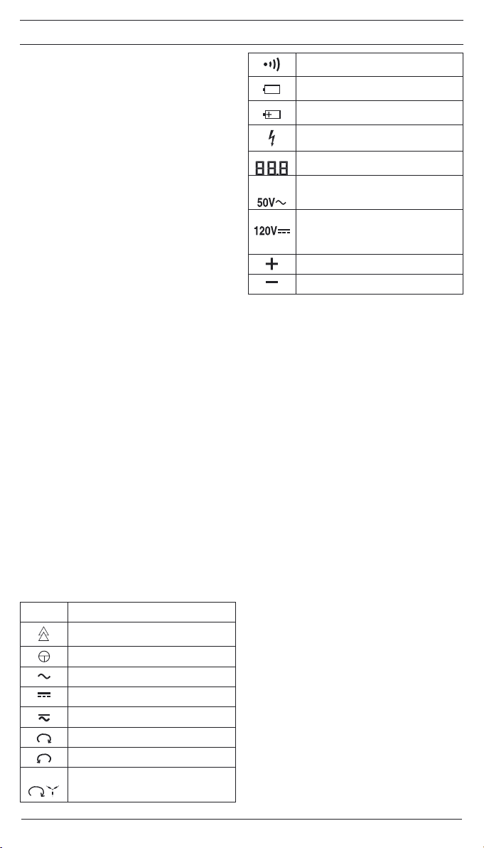
12/ 2008
DUSPOL
®
digital LC
20
Návod k použití zkoušečky
DUSPOL®digital LC
Předtím, než začnete zkoušečku DUSPOL®digital LC
používat, přečtěte si prosím tento návod a dodržujte
uvedené bezpečnostní pokyny!
Obsah:
1. Bezpečnostní pokyny
2. Popis funkcí zkoušečky
2.1 Osvětlení měřeného místa - poznámka
2.2 Poznámka
3. Ověření funkcí zkoušečky
4. Měření střídavého napětí
4.1 Určení fáze střídavého napětí
5. Měření stejnosměrného napětí
5.1 Měření polarity při stejnosměrném napětí
6. Určení pořadí fází u třífázové sítě
7. Měření elektricky vodivého spojení (průchod-
nost)
8. Výměna baterií, ukazatel stavu baterie
9. Technické údaje:
10. Všeobecná údržba
11. Ochrana životního prostředí
1. Bezpečnostní pokyny:
- Při měření držte zkoušečku pouze za izolované ruko-
jeti Aa B a nedotýkejte se měřících hrotů !
- Před použitím přezkoušejte funkčnost zkoušečky
(viz.kap.3)! Jestliže nefunguje jedna či několik funkcí
na ukazateli a nebo je-li zkoušečka zcela nefunkční,
nelze ji dále používat!
- Zkoušečka smí být používána pouze v napěťovém
rozsahu 6 V - 690 V AC/ 750 V DC.
-
Nepoužívejte přístroj s otevřeným otvorem pro baterie.
- Zkoušečka vyhovuje požadavkům ochranného krytí
IP 64.
- Při měření uchopte izolované rukojeti Aa Bzkou-
šečky a celými dlaněmi.
- Zkoušečku nenechte připojenou na napětí déle než
30 sekund (maximální přípustná doba zapojení tmax
= 30 s)!
- Bezporuchový chod zkoušečky je zaručen v rozsahu
teplot - 10 °C až + 55 °C při vlhkosti 20 % až 96 %.
- Není dovoleno zkoušečku rozebírat!
- Chraňte zkoušečku před před poškozením a nebo
znečištěním jejího povrchu.
- Uchovávejte zkoušečku v suchém prostředí.
- Vyvarujte se zranění a vždy po ukončení praáce se
zkoušečkou zakryjte měřící hroty přiloženými kryty!
Upozornění:
Po měření při nejvyšší zátěži (tj. měření 30 s při 690 V AC/
750 V DC) je třeba nechat zkoušečku min. 4 minuty bez
zátěže!
Na přístroji jsou zobrazeny elektrické symboly:
Symbol Význam
Přístroj nebo vybavení k práci pod
napětím
Tlačítko
Střídavý proud
Stejnosměrný proud
Stejnosměrný a střídavý proud
Pravotočivé pole, zobrazení na displeji
Levotočivé pole, zobrazení na displeji
Ukazatel směru otáčivého pole, směr
otáčivého pole zjistit pouze při 50, popř. 60
Hz a při uzemnění sítě
Průchodnost
Symbol baterie, zobrazí se při slabé
baterii
Tento symbol ukazuje pólově správné
uložení baterie
Symbol pro zobrazení fáze (ukazatel na
displeji)
Hodnota napětí zobrazena na displeji, do
ca. 80 V s desetinným místem (1/10 V)
Symbol pro signalizaci překročení horní
hranice hodnoty pro nízká napětí (ELV) při
střídavém napětí (ukazatel na displeji)
Symbol pro signalizaci překročení horní
hranice hodnoty pro nízká napětí (ELV)
při stejnosměrném napětí (ukazatel na
displeji)
Plus pól (ukazatel na displeji)
Mínus pól (ukazatel na displeji)
2. Popis funkcí
DUSPOL® digital LC je dvoupólová zkoušečka podle IEC
61243-3 s digitálním ukazatelem. Jako doplňující zařízení
obsahuje tato zkoušečka osvětlení měřeného místa a dis-
pleje a ukazatel fáze a směru otáčivého pole a zařízením
pro zkoušení průchodnosti. Signalizace při zkoušce prů-
chodnosti je akustická i optická. Pro všechny tyto funkce
potřebuje tato zkoušečka zabudované baterie (2 x Micro
LR03/ AAA). Od napětí ≥ 50 V je možné provádět zkouš-
ku napětí bez baterie. Měření fáze a směr otáčení fází
třífázové sítě lze měřit pouze v případě, že je uzemněn
uzel vinutí.
Přístroj je určen k měření stejnosměrného a střídavého
napětí v rozsahu 6 V až 690 V AC/ 750 V DC. Lze měřit i
polaritu při stejnosměrném napětí.
Zkoušečka se sládá ze dvou zkušebních hrotů L1 Aa L2
Ba propojovacího vedení . Na zkušebním hrotu L1 A
je ukazatel 4a LED diod 3. Přístroj se samovolně spíná
při napětí od 6 V. Funkčnost zkoušečky je možná pouze
při správně vložené a funkční baterii (ve zkušebním hro-
tu L1 A). Na displeji lze zobrazit hodnoty napětí od 6 V
až 690 V AC/ 750 V DC. Překročení mezní hodnoty pro
nízká napětí (ELV, AC 50 V, DC 120 V) je zobrazeno na
dipleji 4.
Oba zkušební hroty jsou vybaveny tlačítky . Při stisk-
nutí obou tlačítek dojde k přepnutí na malý vnitřní odpor
(potlačení induktivních a kapacitních napětí). Tím dojde
k připojení malého vibračního motorku na napětí. Od ca.
200 V se motorek uvede do provozu. Se stoupajícím na-
pětím se zvyšují jeho otáčky a vibrace, tak že přes rukojeť
měřícího hrotu L2 B lze zhruba odhadnout velikost napětí
(např.230/ 400 V Doba měření s malým vnitřním odporem
je závislá na velikosti měřeného napětí. Aby se přístroj
příliš nepřehříval, je instalována tepelná ochrana (zpětná
regulace). Při této zpětné regulaci dochází k poklesu otá-
ček vibračního motorku.
Ukazatel
Ukazatel se skládá z LCD displeje 4a LED diod 3, které
signalizují stejnosměrné a střídavé napětí v hodnotách
od 12; 24; 50; 120; 230; 400 a AC 690 V/ DC 750 V. U
uvedených hodnot napětí se jedná o jmenovitá napětí. Na
LCD displeji se zobrazuje: překročení horní hranice pro
nízká napětí (ELV) 5, fáze 6, symbol pro průchodnos-
ti 7, směr otáčení fází u třífázové sítě 8a 9, přesná
hodnota napětí , polarita při stejnosměrném proudu
a symbol pro slabé baterie . Měřící rozsah pro ply-
nulé měření napětí je nastavován automaticky. Do 80 V
je hodota zobrazena s desetinnou čárkou, při hodotách
vyšších tato čárka odpadá.
Table of contents
Languages:


