IM CL250 5
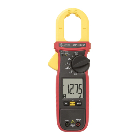
(2) Press the open/close lever to open the transformer jaws and clamp them
onto the conductor under test and take the reading on the display. The
most accurate reading will be obtained by keeping the conductor at the
center of the transformer jaws.
NOTE
●During current measurement, keep the transformer jaws fully closed. Oth-
erwise, accurate measurement cannot be made. The Maximum measur-
able conductor size is 55mm in diameter.
●Unlike in DC current measurement, zero adjustment is not necessary in
AC current measurement. There is no polarity in the reading either.
●The output voltage from the OUTPUT terminal may not reduce to nil even
if the display is zero adjusted with the button. In this case, make
zero adjustment on the recorder or other device that the output voltage is
connected to.
2.4 DC Voltage Measurement
WARNING
Do not make measurement on a circuit above 1000VDC. This may cause
electric shock hazard.
Black test lead
Red test lead
(1) Set the Function Selector switch to the " 400V" or " 1000V" posi-
tion. If the instrument is in the AC mode, press the button once to
select the DC mode. (The instrument is set to the AC mode when it is
powered on.) "DC" should be shown on the upper left corner of the dis-
play.
(2) Slide the terminal cover to the left. Plug the red test lead into the Hi ter-
minal and the black test lead into the Lo terminal.
6 IM CL250
(3) Connect the other end of the tip of the red test lead the positive side of
the circuit under test and the tip of the black test lead to the negative side.
Take the reading on the display. If the test lead connection is reversed,
the "-" sign is shown on the display.
2.5 AC Voltage Measurements
WARNING
Do not make measurement on a circuit above 750V AC. This may cause
electric shock hazard.
Red test lead
Black test lead
(1) Set the Function Selector switch to the " 400V" or " 750V" position.
If the instrument is in the DC mode, press the button once to se-
lect AC mode. (The instrument is set to the AC mode when it is powered
on.) The "AC" should be shown on the upper left corner of the display.
(2) Slide the terminal cover to the left. Plug the red test lead into the Hi ter-
minal and black test lead into the Lo terminal.
(3) Connect the tip of the test leads to the circuit under test. Take the reading
on the display.
IM CL250 7
2.6 Resistance Measurement
WARNING
Never try to make measurement on a circuit that is not de-energized.
Red test lead
Black test lead
(1) Set the Function Selector switch to the " " position. The "Ω" should
be shown on the upper right corner of the display.
(2) Slide the terminal cover to the left. Plug the red test lead into the Hi ter-
minal and the black test lead into the Lo terminal.
(3) Check that the display reads "OL". Then, short the tip of the test leads
together and check that the display reads "0".
(4) Connect the tip of the test leads to the circuit under test and take the
reading on the display.
NOTE
●When the tip of the test leads is shorted together, the display may read a
very small resistance instead of "0". This is the resistance of the test leads,
not fault.
●If one of the test leads has a break, the display reads "OL".
2.7 Continuity Check (400Ωrange fixed)
WARNING
Never try to make measurement on a circuit that is not de-energized.
(1) Set the Function Selector switch to the " " position.
(2) Slide the terminal cover to the left. Plug the red test lead into the Hi ter-
minal and the black test lead into the Lo terminal.
(3) Press the button to select the continuity check mode. The " "
symbol should be shown on the display.
(4) Check that the display reads "OL". Then short together the tip of the test
leads and make sure that the display reads "0" and the buzzer beeps.
8 IM CL250
(5) Connect the tip of the test leads to the circuit under test. The buzzer
beeps when the resistance is about 50Ωor less.
NOTE
●When the tip of the test leads is shorted together, the display may read a
very small resistance instead of "0". This is the resistance of the test leads,
not a fault.
●If one of the test leads has a break, the display reads "OL".
2.8 MAX Measurement (Response time : 400ms)
The MAX measurement mode is used to display a maximum reading over a
certain period of time. This function is available on all ranges other than Ω
ranges.
WARNING
●Do not make measurement on a circuit above 750VAC or 1000VDC. This
may cause electric shock hazard.
●Do not make measurement with the test leads connected to the instru-
ment.
(1) Set the Function Selector switch to the desired position.
(2) Press the button to select the MAX measurement mode. " "
should be shown on the display.
(3) In order to take a correct reading, press the button once after
clamping the jaws onto the conductor or connecting the test leads to the
circuit under test.
(4) The display shows the maximum reading during measurement.
(5) Press the button once again to return to the normal measurement
mode.
NOTE
●Data Hold function is disabled in MAX measurement mode.
●For measurement over a period more than 10 minutes, disable the Sleep
function according to the User’s Manual in section 3.1 Sleep Function.
Otherwise, the instrument automatically turns itself off in about 10 minutes.
