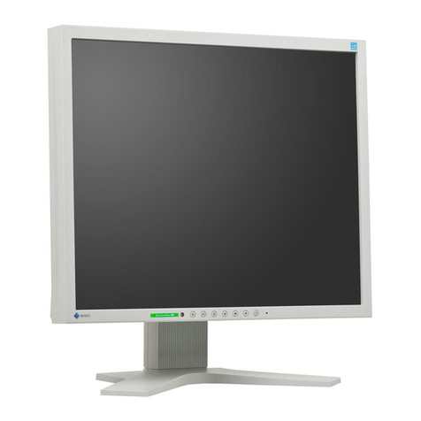
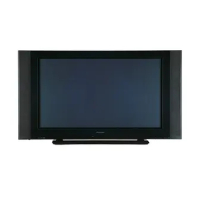
BGH BP4201S User manual

SER
SERVICE MANUAL
VICE MANUAL
Model : BP4201S(NTSC-PAL M/N)
PLASMA DISPLY PANEL

CONTENT
CONTENT
- 1 -
SAFETY INSTRUCTIONS.........................................................................................2
FUNCTIONAL OVERVIEW.......................................................................................3
BLOCK DIAGRAM..................................................................................................6
PDP TV BOARD LOCATION....................................................................................7
PIN CONFIGURATIONS..........................................................................................8
TROUBLESHOOTING..............................................................................................9
SPECIFICATIONS....................................................................................................13
PCB LAYOUT..........................................................................................................20
SCHEMATIC DIAGRAM..........................................................................................22
PARTS LIST.............................................................................................................36
EXPLODED VIEW ...................................................................................................43

SAFETY INSTRUCTIONS
SAFETY INSTRUCTIONS
- 2 -
IMPORTANT SAFETY NOTICE
Many electrical and mechanical parts in this chassis have special safety-related characteristics.
These parts are identified by in the Schematic Diagram and Parts list.
It is essential that these special safety parts should be replaced with the same components as recommended in
this manual to prevent Shock, Fire, or other Hazards.
Do not modify the original design without permission of manufacturer.
Leakage Current Hot Check (See below Figure)
Plug the AC cord directly into the AC outlet. Do not use a line Isolation Transformer during this check.
Connect 1.5K/10watt resistor in parallel with a 0.15uF capacitor between a known good earth ground
(Water Pipe, Conduit, etc) and the exposed metallic parts. Measure the AC voltage across the resistor
using AC voltmeter with 1000 ohms/volt or more sensitivity. Reverse plug of the AC cord into the AC
outlet and repeat AC voltage measurements for each exposed metallic part. Any voltage measured must
not exceed 0.75 volt RMS, which is, corresponds to 0.5mA. In case any measurement is out of the limits
specified, there is possibility of shock hazard and the set must be checked and repaired before it is
returned to the customer.

FUNCTIONAL OVER
FUNCTIONAL OVERVIEW
VIEW
- 3 -
FRONT VIEW
ŒInput source selection button
´Menu selection button
ˇVolume adjustment buttons
(also select items on the OSD)
¨Channel selection buttons
(also move items on the OSD)
ˆEnter button
(Confirm your choice, 42” only)
ØPower On / Off button
∏Power Indicator
”Remote Control Sensor
REAR VIEW
ŒSERIAL Input
´
DVI Input
ˇPC RGB Input
¨Component 1 & 2(Y/Pb/Pr, Audio(L/R))
ˆSpeakers Out (8
Ω
) : Connect external speakers.
ØAV Input 1
∏AV Input 2
”RF IN : 75
Ω
Coaxial connector for Aerial / Cable Network.
’AV Input 3
˝ S-Video Input
Ô Audio Output(L/R)
PC DVI Audio in
Ò Power Input : Connect the supplied power cord.
SERIAL Input DVI Input
PC RGB Input
Y Pb Pr L R
Component 2 Speakers OUT( ) AV Input 1
V L R AV Input 2
V L R AV Input 3
V L R S-Video
Input Audio
Output
Component 1 L
RPC DVI
Audio in Power
(AC100-240V-, 50/60Hz)
3
RL
RF IN

FUNCTIONAL OVER
FUNCTIONAL OVERVIEW
VIEW
- 4 -
REMOTE CONTROLLER
1. POWER
Power On/Off.
2. MUTE
Toggles speaker/headphone sound mute status.
3. SLEEP
Displays current sleep timer value by minute when no sleep timer OSD
activated.
Setup minimum sleep timer value more than current sleep timer value when
sleep timer OSD activated.
If sleep timer is maximum value, disables sleep timer.
4. Dual I-II
Displays MTS of sound format when MTS OSD is not activated.
Changes sound format when MTS OSD is activated.
5. ARC
Displays aspect ratio of image when aspect ratio OSD is not activated.
Changes aspect ratio when aspect ratio OSD is activated.
6. 0~9
Enters digit value to change program directly.
7. 100
Setting TV channel.
8. SWAP
Swaps main input source and PIP input source.
9. PC
Changes to PC / DVI source.
If current input source is PC, input source is changed to DVI.
10. MENU
You can use this button to have the menu display on the screen
11. VOL+/VOL-
Volume up/down adjust
12. ENTER
While using on-screen menus, press this button to activate or change a
particular item.
13. CAPTION
If current input mode is Video or TV, Display the CAPTION or change the
CAPTION mode.
14. SOURCE
Activates source change OSD when source change OSD is not activated.
Deactivates source change OSD when source change OSD is activated.
POWER
MUTE SLEEP STILL INFO
DUAL I-II
PRE-CH
CH+
MENU
CAPTION ADD/ERASE
EXIT
CH-
VOL- VOL+
ARC PSM SSM
PIP
P.INPUT
P.POSITION
P.SIZE
SOURCE
P
C
S
W
A
P
S
.
S
E
L
E
C
T
T
V
1 2 3
4 5 6
7 8
0
9
100
ENTER
!
“
‘
+
=
Q
@
#
$
%
^
&
*
(
)
1
2
3
4
5
6
7
8
0
9

FUNCTIONAL OVER
FUNCTIONAL OVERVIEW
VIEW
- 5 -
REMOTE CONTROLLER
15. INFO
Displays input source information.
16. STILL
Toggles status between motion and still image.
17. SSM(Sound Standard Mode)
Displays sound standard when sound standard OSD is not activated.
Changes sound standard when sound standard OSD is activated.
18. PSM(Picture Standard Mode)
Displays picture standard when picture standard OSD is not activated.
Changes picture standard when picture standard OSD is activated.
19. PIP
Toggles PIP status
- P.INPUT
Changes PIP input sources when PIP is on.
- P.POSITION
Changes PIP position when PIP image size is not double screen.
- P.SIZE
Changes PIP image size when PIP is on.
20. PRE-CH
Changes to last tuned program.
21. S.SELECT
Selects main / PIP sound source when PIP is on.
22. TV
If current input source is not TV, changes to TV input source.
23. EXIT
Exit from the OSD menu.
24. CH+/CH-
Channel up/down
25. ADD/ERASE
Add TV channel or Erase when editing TV channels.
POWER
MUTE SLEEP STILL INFO
DUAL I-II
PRE-CH
CH+
MENU
CAPTION ADD/ERASE
EXIT
CH-
VOL- VOL+
ARC PSM SSM
PIP
P.INPUT
P.POSITION
P.SIZE
SOURCE
P
C
S
W
A
P
S
.
S
E
L
E
C
T
T
V
1 2 3
4 5 6
7 8
0
9
100
ENTER
!
“
‘
+
=
Q
@
#
$
%
^
&
*
(
)
1
2
3
4
5
6
7
8
0
9

BLOCK DIAGRAM
BLOCK DIAGRAM
- 6 -
MAIN/RF BOARD’S BLOCK DIAGRAM
DTV1_Y / Pb / Pr
PC (R / G / B / H / V)
G [9:2]
AV1 CVBS
MUX_LU1 / CH1
TA6422
VCT49xyi
MST37
(ADC/TMDS)
R / G / B [9:2]
AV 1 L/R
P
A
N
E
L
L
V
D
S
T
X
T
H
C
6
3
L
V
D
M
3
R
C
H
1
C
H
2
RX 0 / 1 / 2 / CLK / - , +
I2C
I2C
Display Output
(R/G/B [9:2]
/H/V/EN/CLK) LVDS
(CLK/A/B/C/D -, +)
FLASH MEMORY
MBit
Memory Interface
(A0-19/D0-15/ CE/OE/WE)
DDR SDRAM
DDR SDRAM Interface
(MA0-12/MD0-31)
I
M
A
G
E
P
R
O
C
E
S
S
O
R
P
W
2
1
Satrun NTSC (USA ) BLOCK DIAGRAM
CLK/H/V/DE
DTV2_Y / Pb / Pr
AV2 CVBS
Svideo C / L
AV3 CVBS
SAW FilterTuner VIF
DTV1 L/R
AV3 ,Svideo L/R
AV 2 L/R
DTV2 L/R
Tuner SIF
TPA3002D2 Internal Speaker L /R Out
External Speaker L /R Out
PC/COMPONENT Video
RF / Video
Sound In
Audio Out
Audio L/R Out
SATURN NTSC - PAL M/N BLOCK DIAGRAM

PDP TV BOARD LOCA
PDP TV BOARD LOCATION
TION
- 7 -
PDP TV PCB LOCATION

PIN CONFIGURA
PIN CONFIGURATIONS
TIONS
- 8 -
1 Tx 2
-
2 Tx 2
+
3 Grounding
4 No connection
5 No connection
6 DDC Clock (SCL)
7 DDC Data (SDA)
No Connection
9 Tx 1
-
10 Tx 1
+
11 Grounding
12 No connection
13 No connection
14 DDC Input Power (+5V)
15 Self-Raster
16 Hot Plug Detect
17 Tx 0
-
1 Tx 0
+
19 Grounding
20 No connection
21 No connection
22 Grounding
23 Tx CLK
+
24 Tx CLK
-
C3 No connection
C5 No connection
C4 No connection
C2 No connection
C5 No connection
C1 No connection
DVI connector
Pin Signal Pin Signal
This model did not support a R,G,B signal on DVI connection
1 Red (R)
2 Green (G)
3 Blue (B)
4Grounding
5 Grounding (DDC)
6 Red (R) Grounding
7Green (G) Grounding
Blue (B) Grounding
9 Reserved
10 Sync Grounding
11 Grounding
12 Data (DDC)
13 Horizontal sync.
14 Vertical sync.
15 Clock (DDC)
RGB Input connector
Pin RGB IN Pin RGB IN
Pin Name Description
1 GND Ground(Y)
2 GND Ground(C)
3 Y Intensity(Luminance)
4 C Color(Chromiance)
At the TV(Female)
12 34
DVI CONNECTOR
RGB INPUT CONNECTOR
S-VIDEO CONNECTOR

TROUBLESHOOTING
TROUBLESHOOTING
- 9 -
Problem
No picture or sound
Poor picture, good sound
Picture is OK but there is no sound
Remote control does not operate.
No image on a specific channel
Image is not stable and may
appear to vibrate; horizontal bars
appear.
No color on a specific channel (a
black & white image)
Only snow and noise appear on
the screen
Possible solution
■Make sure the TV is plugged in.
■Make sure the power cord is connected to a wall socket
correctly.
■Check the antenna connections.
■Check the volume.
■Adjust the brightness and contrast in the picture menu.
■Check antenna or cable connections.
■Press the MUTE button on the remote control.
■Check another channel.
■Press the VOL + button to increase the volume.
■Batteries could be weak. Replace the batteries to a new
ones.
■Locate the PDP at least one meter away from
fluorescent lights.
■Clean the transmission window of the remote control.
■Make sure the channel selection is correct.
■Change the antenna direction to the right or left.
■Adjust the fine tuning of the channel.
■Adjust the fine tuning of the channel.
■Make sure there is no powerful electromagnetic wave
interference from the transmitting station.
■Stop using a hair drier, electric drill or electric blender.
■Check other channels to see if the specific channel is
broadcasting a black & white program.
■Adjust the color in the picture menu.
■Check the antenna and cable connections.
■Check the another channel.
Simple check point before disassembly the back cover.

TROUBLESHOOTING
TROUBLESHOOTING
- 10 -
NO POWER
NO Power
Check power cord change
powercord
Check Power inlet & Harness
Check Fuse
<F101>
T250V,8A
Check SMPS
outputVoltage Change SMPS
ChangeMainboard
or key pad board
Change the Fuse
Change
Power Inlet or Harness
o.k
nogood
nogood
nogood
nogood
o.k
o.k
o.k

TROUBLESHOOTING
TROUBLESHOOTING
- 11 -
NO PICTURE
NO Picture
Check power LED color Push
power button
Check SMPS output voltages
<VE, VS, VSCAN, VSET, VA>
Check
LVDS. DC power connection
on Main board
Check SMPS
output voltage
after disconnected
CN8003
(on SMPS)
Check SMPS
output after disconnected
CN8002
(on SMPS)
Change Main board
Change SMPS board
Change X- Main board
Change
Y- Main & Y -buffer
boards
Re connect
LVDS. DC power
connecters
red color
blue color
good
good
no good
good
good
no good
no good
no good

TROUBLESHOOTING
TROUBLESHOOTING
- 12 -
NO SOUND
NO Sound
Check"Mute "ON? Release
"Mute" function
by remote controller
Check Volume Level Low ?
Checkaudio
Inputconnectors
Checkspeakerconnectors Fasten
speakerconnectors
Changespeakerunits
Fasten
input connector
Increase
VolumeLevel
nogood
nogood
very low
on
off
good
o.k
good

SPECIFICA
SPECIFICATIONS
TIONS
- 13 -
KEY COMPONENTS
Key Components
Key Components Chip Model Maker Comments
Image processor PW21 -10Q Pixelworks
ADC MST37 MStar
TMDS MST37 MStar
Video Decoder VCT49XYi Micronas
TV Tuner UV1316 PHILIPS
3D Comb Filter None -
Deinterlacer Built-In Pixelworks
Video Enhancer Built-In Pixelworks
V-CHIP VCT49XYi Micronas
Sound Processor VCT49XYi Micronas
Sound Amplifier TPA3002D2 Texas Instruments
MAIN/RF BOARD SPECIFICATION SUMMARY
Items Specifications
Target Panel Size PDP 42/50 Inch
Aspect Ratio 16 9
852x480
Resolution
Refresh Rate 50Hz, 60Hz
Maximum
Pixel
Rate 110 MHz
Display
Interface Single Channel LVDS
H Frequency Range 20 ~ 82 kHz
V Frequency Range 55 ~ 90 Hz
Maximum resolution 1280x1024 60Hz
Maximum pixel rate 110 MHz
DTV mode support 720P, 1080i
Analog PC
Separate / Composite / SOG sync support
H Frequency Range 20 ~ 82 kHz
V Frequency Range 55 ~ 75 Hz
Maximum resolution 1280x1024 60Hz
Maximum pixel rate 110 MHz
Digital PC
(DE Mode)
DTV mode support 720P/1080i
Supported
Signals

SPECIFICA
SPECIFICATIONS
TIONS
- 14 -
MAIN/RF BOARD SPECIFICATION SUMMARY
CVBS , S-Video
NTSC-M
PAL-BGHI
NTSC-4.43
SECAM
PAL M/N
Component 1/2
(DTV/DVD)
1080i
720P
480i / 576i
480P / 576P
TV NTSC / PAL-M / PAL-N Systems
TV ANT In (75 ohms coaxial cable)
AV1 Composite RCA In (75 ohms 0.7/1.0 Vp-p)
AV2 Composite RCA In (75 ohms 0.7/1.0 Vp-p)
AV3 Composite RCA In (75 ohms 0.7/1.0 Vp-p)
S-Video S-Video In
Connection
(Video)
Component1/2 Y-Pb-Pr DTV RCA In (75 ohms , 0.7Vp-p)
PC Analog DSUB In (Analog 75 ohms ±10%, 0.7Vp-p ±5%)
PC DVI DVI-I Type (Digital Only)
TV Tuner SIF In
AV1 RCA Stereo Sound In (500mVrms)
AV 2 RCA Stereo Sound In (500mVrms)
PC RCA Stereo Audio Line In (500mVrms)
Video RCA Stereo Audio Line In (500mVrms)
Component1/2 RCA Stereo Audio Line In (500mVrms)
Internal Speaker Out
8W x 2 Stereo Speaker (8 ohms)
External Speaker Out
8W x 2 Stereo Speaker (8 ohms)
Connection
(Audio)
Audio Out RCA Stereo Audio Line In (500mVrms)
Tuning System PAL System
Tuning Range 45MHz~889MHz
No of Programs AIR 69 CABLE(STANDARD/HRC/IRC) 125 Channels
Sound System M(BTSC)
TV
MTS Support Mono / Stereo / SAP
Color 8Bit color (256 color palette from 565 16 bit color)
OSD Type Graphic & text
Language Support Unicode string format
English /Spanish /Portuguese/German /Italian/Nederland
OSD
Maximum OSD Size
540(Horizontal)x370(Vertical)

SPECIFICA
SPECIFICATIONS
TIONS
- 15 -
MAIN/RF BOARD SPECIFICATION SUMMARY
Image Adjustment
Contrast / Brightness / Sharpness / Color / Tint
Color Temperature
Picture Standard Select
Image aspect ratio
TV Function
Tuner Mode Option Select
Auto Search
Channel Add/Erase
Manual Fine Tune
Sound Function
Volume
Balance
5 band equalizer
Mono / stereo / SAP Sound
Sound Standard select
User
Functions
PC Function
Auto adjustment
Frequency adjustment
Phase adjustment
H/V position adjustment
Up to 32 analog pc mode memorize
PIP Function
Pip On/Off
Pip source select
Pip size
Pip position
Pip swap
Pip sound select
Timer
Sleep time select
Current / On / Off time adjustment
On time channel / volume
Miscellaneous
User default reset
OSD Language select
Blue Screen
OSD Tone
Pixel Shift
Wiper
BG Gray

SPECIFICA
SPECIFICATIONS
TIONS
- 16 -
SUPPORTED TIMINGS
Section
Resolution
H
Frequency
( kHz )
V
Frequency
( Hz )
Pixel
Frequency
( MHz )
Comment
640x400 37.861 85.08
31.5
640x350 31.469 70.087
25.175
640x350 37.861 85.08
31.5
640x480 31.469 59.94
25.175
640x480 35.000 66.667
30.24
640x480 34.940 69.884
28.513
640x480 37.861 72.809
29.765
640x480 37.500 75.0
31.5
640x480 43.269 85.008
36.0
640x480 45.540 90.0
37.889
720x400 31.469 70.087
28.322
720x400 37.927 85.039
35.5
800x600 35.156 56.25
36.0
800x600 37.879 60.317
40.0
800x600 43.764 70.02
45.513
800x600 48.077 72.188
50.0
800x600 46.875 75.0
49.5
800x600 53.674 85.061
56.25
800x600 56.880 90.0
60.065
832x624 49.726 74.551
57.284
1024x768 48.780 60.001
64.11
1024x768 48.363 60.004
65.0
1024x768 56.476 70.069
75.0
1024x768 57.703 72.039
78.476
1024x768 60.241 74.927
81.724
1024x768 60.030 75.029
78.75
1024x768 68.677 84.997
94.5
1024x768 72.810 90.0
100.187
1152x864 53.700 60.0
81.624
1152x864 62.932 69.924
96.663
1152x864 67.500 75.0
104.993
1152x870 68.681 75.062
100.0
1152x900 61.846 66.0
94.787
1152x900 72.713 76.047
105.561
1280x720 47.760 60.0
74.481
1280x720 52.500 70.0
89.040
1280x720 54.072 72.0
91.706
PC
1280x720 56.400 75.0
95.654
1280x768 47.700 60.0
80.136
1280x768 60.150 75.0
102.977
1280x960 60.000 60.0
102.104
1280x960 59.640 60.0
102.104
1280x1024 63.337 59.978
108.18
1280x1024 63.981 60.02
108.0
1280x1024 64.754 60.06
108.992
1280x1024 63.600 60.0
108.883
720x480 15.735 59.94
13.500 Interlace
720x576 15.735 50.0
13.595 Interlace
720x480 31.469 59.94
25.175
720x576 31.250 50.0
26.566
1280x720 44.964 59.94
74.176
1280x720 37.500 50.0 60.466
1920x1080 33.750 60.0 74.25 Interlace
1920x1080 28.125 50.0 70.723 Interlace
DTV
1920x1080 31.250 50.0 72.000 Interlace

SPECIFICA
SPECIFICATIONS
TIONS
- 17 -
LED OPERATIONS
POWER MANAGEMENT
FUNCTIONS
Status Color Operation
Power Off Red On
Normal Green On
Green Timer On Red On
DPMS Off Red Blink (2 sec)
Function Description
Ima e color control
Brightness PC & Video
Contrast PC & Video
Sharpness PC & Video
Color(Saturation) Video only
Tint Video only
Adjust & save each color setting value
Color Temperature
PC Color temperature : Custom , Mode1, Mode2, Mode3
RGB adjus table in custom color temperature mode
Video color temperature : Cool2, Cool1, Normal, Warm1, Warm2 (Cool -> Warm color)
Picture Standard
PC color standard adjusted by Brightness, contrast, sharpness
Video color standard adjusted by Brightness, contrast, sharpness, color
PC color standard : Custom, High, Middle, Low
Video color standard : Custom, Dynamic, Standard, Movie, Mild
Picture Aspect Ratio
Video Image : Auto-Wide, Wide(Full screen), Panorama, Zoom, 4:3, 14:9
PC Image : Wide(Full screen), 4:3
Ima e Lock
H/V position adjustment
Frequency(Clock) adjustment
Phase(Fine) adjustment
Auto image adjustment
DTV phase(Fine) adjustment
Others Image still
Video Image
Spection Description
DPMS Power management by suspend, Standby, DPMS off signal sync
Sync duration : 3 sec
DPMS warning duration : 5 sec
DPMS power consumption : under 5 watt
No Signal PM Power management by abnormal, no sync, no cable connection
Sync duration : 10 minute

SPECIFICA
SPECIFICATIONS
TIONS
- 18 -
FUNCTIONS
Sound
Function Description
Basic Adjustment Speaker Volume, Headphone volume, Balance, Equalizer, Auto volume level, Mute
Equalizer Equalizer Band : 120Hz, 500Hz, 1,5kHz, 5kHz, 10kHz
Sound Standard Sound color standard adjusted by equalizer bands
Sound standard : Custom, Standard, Music, Movie, Speech
TV Sound System M (BTSC)
TV Sound Format
Detect & Adjustment
Sound Format Adjustment Default mode
Mono Mono Mono
Stereo Mono / Stereo Stereo
SAP Mono / SAP SAP
SAP + Stereo Mono / Stereo / SAP SAP
TV
Function Description
Tunin
Tuning Frequency Range : 40MHz~889MHz
NTSC , PAL M/N
M (BTSC)
Country Support USA, BRAZIL, ARGENTINA
Other Functions Channel Add/Erase
Channel Sort
PIP
Function Description
Main & PIP Input
Condition
Main Sub
Component1,2(DTV/DVD)
DVI
RGB
S-Video
RF
AV 1/2/3
S-video
AV 1/2/3
RF
RGB
DVI
Component1,2(DTV/DVD)
PIP source chan e Connected & condition available according to main input can be changed
PIP Size
Large Horizontal Double Vertical Double
Other Functions
Pip Position in large mode : Right-Bottom, Right-Top, Left-Top, Left-Bottom
Pip Swap
Sound swap

SPECIFICA
SPECIFICATIONS
TIONS
- 19 -
FUNCTIONS
Timers
Function Description
Sleep Timer Power off when sleep time elapsed
Timer setting range : Off / 30 / 60 / 90 / 120 / 150 / 180 minute
Current Time Clock Hour(0~23), Minute(0~59)
On/Off Time
On /Off time : Hour(0~23), Minute(0~59)
On / Off time Enable / Disable
On time channel, volume
Power on, source changed to TV, channel changed to on time channel & set on time volume
when current time is on time.
Power off when current time is off time.
Setup Functions
Function Description
Reset to Default Reset all user setting value to system default
Refer to default value in OSD structure section
OSD Lan ua e Supported language : world wide all languages by Unicode string
English, Spanish, Portuguese
Other Functions OSD background blend
Blue screen on / off : Adjusts blanking screen color to blue / black
Other manuals for BP4201S
1
Table of contents
