Bienfang Vacuum Press 3648H User manual


Bienfang®Vacuum Press® 3648H, 4468H and 5298H
Programmable Combination Vacuum Presses
OWNERS MANUAL

Specifications for Vacuum Press
Important Safeguards
Features
Installation and Preparation
Installation and Preparation
Identification of Controls
Procedures for Use
Procedures for Use
Recommended Time and Temperature Setting
Periodic Maintenance
Warranty
Troubleshooting
Replacement Parts
CONTENTS
2
3
3
4
5
6
7
8
9
10
10
11
12
SPECIFICATIONS FOR THE BIENFANG®VACUUM PRESS
2
5298H 4468H 3648H
Catalog Number 2170 2160 2180
Floor Stand included 2165 2167
Working Area 48" x 96" x 1" 44" x 68" x 1" 36" x 48" x 1"
Outside Dimensions 109" x 65" x 7" 77" x 57" x 7" 57" x 48" x 1"
Net Weight 375 lbs. 215 lbs. 135 lbs.
Shipping Weight 800 lbs. 500 lbs. 350 lbs.
Power Requirements 208-230V/Single Phase 208-230V/Single Phase 208-230V/Single Phase
Power Consumption Approx. 5925 Watts Approx. 3390 Watts Approx. 1700 Watts
Watts-amps @ 230VAC (26 amps) @ 230VAC (15 amps) @ 230VAC (11 amps)
Plug Type NEMA L14-30P NEMA L14-20P NEMA L14-20P
Twist Lock Twist Lock Twist Lock
• International plugs supplied by user.

FEATURES
3
Please read the entire manual and fully understand the
proper operating procedures before proceeding to use
the press.
1. Place the vacuum press in either a BIENFANG® Floor
Stand or a sturdy, flat, level surface and ensure the
feet and hinges are properly adjusted. The press should
not be located in the direct path of air conditioning or
room-cooling vents.
2. Keep the vent cloth positioned so that it covers the
vacuum manifolds (located in the rear corners of the
press) and does not extend across the edge of the
rubber diaphragm. Failure to do so will result in tempo-
rary loss of vacuum.
3. Place all materials inside the press so that they fit into
the recessed chamber in the base. If any materials
extend across the edge of the rubber diaphragm, they
will prevent a seal and cause either low vacuum or no
vacuum at all.
4. When opening and closing the press grasp both han-
dles and keep your body, head and hands away from
the press opening.
5. Foreign objects such as knives, tools, rulers, paper
clips and markers should be kept out of the press and
away from the press opening at all times.
6. Do not stack boards in the press. Placing a smaller
board on top of a larger one may cause lines or dents
in the aluminum platen.
7. Do not use an exposed blade to cut materials in the
press. A slice or puncture in the rubber diaphragm will
result in loss of vacuum.
8. Allow the vacuum level to drop before opening the
press.
9. Turn the power breaker OFF and keep the press in the
closed position when not in use. Disconnect the power
supply before cleaning or replacing parts.
10. High-pressure gas springs make opening and closing
the press easier. If they are to be removed, the top
MUST be held in the fully opened position for safety
and to prevent damage.
Contact your authorized Hunt dealer or Hunt Technical
Service in the event the press needs service for parts not
covered in this Owner’s Manual.
IMPORTANT SAFEGUARDS
The Bienfang® Vacuum Press 3648H, 4468H and 5298H
presses are professional mounting and laminating systems
designed to provide the highest quality results with maximum
versatility and ease of operation. The combination of two
machines in one – a dry mount press and cold vacuum frame –
allows the quick professional application of dry mounting adhe-
sives and laminates, as well as wet and spray adhesives. The
presses decrease labor costs and increase production while
minimizing operator training and supervision.
Specific features and benefits include:
• Easy to Use: Close the top, press a key and wait for the
signal that the work is done - automatic operation frees
the operator for other duties.
• Digital Display: lets the operator know at all times the
vacuum level, platen temperature and cycle time remain-
ing; the display is switchable between showing the original
settings and actual readings.
• Locking: All current models have side latches. Previous
models have the front latch.
•Programmable Settings: The operator can store up to six
programs in memory for repeatable processes. Time and
temperature settings for each program are stored for
quick, easy access.
• High, Uniform Vacuum Pressure: 10-13 psi (20-27" Hg)
ensures good bond penetration for consistent, professional
results.
• Automatic Pressure Adjustment: Self adjusts for boards up
to 1" thick, or mounts several pieces of varying thickness
at one time — without additional set-up time.
• Double-Duty Top: Specially constructed heavy-duty flat top
doubles as work or storage space when the press is not
in use.
• Floor Stand: Optional for 3648H and 4468H. Used to
make the presses freestanding units rather than tabletop
machines. Each incorporates one shelf support. The
5298H model comes with a floor stand.

Each Bienfang®Vacuum Press 3648H, 4468H and 5298H
(floor stand included) is fully assembled, calibrated and
tested at the factory to pull a high level of vacuum in a
minimum amount of time. Once passed by the Quality
Control Department, the completely tested press and pump
are packaged and shipped together to ensure that each
customer receives a complete and tested unit.
During shipping and uncrating, the alignment of the top
and base of the press may be altered and require adjustment
by the user. In addition, placing the press on an uneven or
warped table surface may require adjustment of the leveling
feet and hinges by the user. Follow these instructions to
ensure proper operation.
Installation
For consistent long-term operation of the 3648H and
4468H, Bienfang recommends using the appropriate
Vacuum Press Floor Stand. First assemble the Floor Stand
following the directions supplied with it, then lift the press
out of the shipping crate and position it on the Floor Stand
so that each of the four feet fit into the top of a Floor Stand
leg. Using the bolts supplied with the Floor Stand, bolt the
two support brackets on each leg into the corresponding hole
underneath the frame. When complete, tighten each bolt
fully and the press can be moved into position.
As an alternative to the 3648H/4468H Floor Stand, a
heavy-duty, flat level table can be used. The press should sit
completely on the table, so a 46" x 53" or 57" x 77" surface
area is required. The recommended surface material is 3/4"
Grade B plywood or better. A table height of 30" is typical.
Make sure all four adjustable feet are fully screwed in, place
the press on the prepared table and adjust the feet individu-
ally so that the press is level front to back and side to side.
For a Qualified Electrician
The Bienfang Vacuum Press 3648H and 4468H are rated
for 230VAC/60 Hz Single Phase (with Neutral) on a 20 Amp
circuit. Actual line voltages between 208-230 VAC are
acceptable. The press power-cord has a NEMA L14-20P
twist lock plug which is UL listed for use in this application.
The 5298H is rated for 230VAC/60HZ Single Phase (with
Neutral) on a 30 Amp circuit. Actual line voltages between
208-230VAC are acceptable. The press power cord has a
NEMA L14-30P twist lock plug, which is UL listed for use in
the application.
If you choose to hard-wire direct to a junction box, the
12-gauge power cord (3 wire plus ground) is color-coded
using the conventional standards:
Red - L1 (Hot) White - Neutral
Black - L2 (Hot) Green - Ground
Note that separate ground and neutral lines must be
installed or the pump will not operate and the press will not
meet UL standards or safety codes.
After hookup is complete, check with the Power Switch ON,
the tacking iron outlet on the front of the press measures
110-120VAC between L1 and Neutral, that there are 0 Volts
between neutral and Ground and that there is continuity
between Ground and press frame..
Note: If there are any questions, call your distributor or Hunt
Technical service at 888-240-6021.
Leave at least 5" between the rear of the press and the wall
so the top has room to open easily. The vacuum pump
should be placed on the floor behind the press. The plastic
vacuum line tubing is already connected underneath the
press and the free end will have to be attached to the inlet
side of the pump. To attach, depending on the pump fitting,
slide the vacuum line firmly into the chrome fitting on the
pump until it snaps in place or tighten the brass nut onto
the pump fitting.
(TIP: Hunt recommends the use of a static guard mat in
high-static areas).
With the Power Switch OFF, plug the vacuum pump power
cord into the electrical outlet marked Vacuum Pump Only
on the rear of the press.
To check operation, close the press and turn the Power
Switch ON (on the side of the press). The programmable
systems controller should come on and display room
temperature, 0 time and 0 vacuum.
INSTALLATION AND PREPARATION
4

Press the vacuum "Manual On/Off" key and the pump
should run. If not, check that the pump is plugged into the
back of the press and then have a qualified electrician re-
check the electrical hookup. (If separate ground and neu-
tral lines are not installed, the pump may not operate even
though the display illuminates.)
After turning on the pump, the display should read a mini-
mum of 20" of Hg for: 3648H within 40 seconds, 4468H
within 1 minute and for the 5298H within 2 minutes. If
there is any difficulty in drawing a proper vacuum, refer to
the Owner’s Adjustment Procedures section of Page 24 of
this manual.
Press the "Heat On" key and the press should begin to heat
up to 180ºF (+/- 2ºF) within 15-20 minutes. If not, call
Hunt Technical Service at 888-240-6021.
The press is now ready for use.
Adjustment Procedures
Proper leveling of the press and adjustment of the hinges
and latch are necessary to consistently achieve proper
vacuum. Check the following owner adjustment procedures,
in the order listed, if any difficulty arises.
Leveling
If the press is not placed on a sturdy, flat, level surface,
proper operation cannot be guaranteed. Ensure press level-
ness by opening the press and placing a 2’ carpenter’s level
on the frame. Shim the floor stand legs so that the frame of
the press is level (both front-to-back and side-to-side). If not
on a floor stand, adjust the corner feet until the press is level.
Hinge Adjustment
After leveling the press, check the adjustment of the rear
hinges. These might shift during shipment, handling or
rigorous use and are essential to proper alignment of the
top to the base. To realign, follow these instructions:
1. Close and set temperature to 180ºF.
2. As your assistant holds open the lid, remove the clips
from the bottom of the gas springs (located around the
bottom socket head only) using the needle nose pliers.
This could possibly be done by hand. Bump first the
bottom of the gas spring off the ball sockets from both
left and right sides of the machine. Then remove the top
by grasping the gas spring and tilt away from ball stud.
Spring will come off. The gas springs MUST be taken
completely off the machine.
3. Loosen (do not remove) screws in the slotted holes of the
hinges, located on the back of the machine.
4. Once machine is fully heated, start the vacuum. Give unit
45 seconds to 1 minute to pull full vacuum. If no
vacuum is achieved, walk around machine and put slight
pressure on lid in various sections until a full vacuum is
achieved.
5. Tighten set screws on hinges and replace gas springs.
If any further questions arise, contact your authorized
Bienfang®dealer or the Hunt Technical Service Department
at 1-888-240-6021.
INSTALLATION AND PREPARATION (CONTINUED)
5
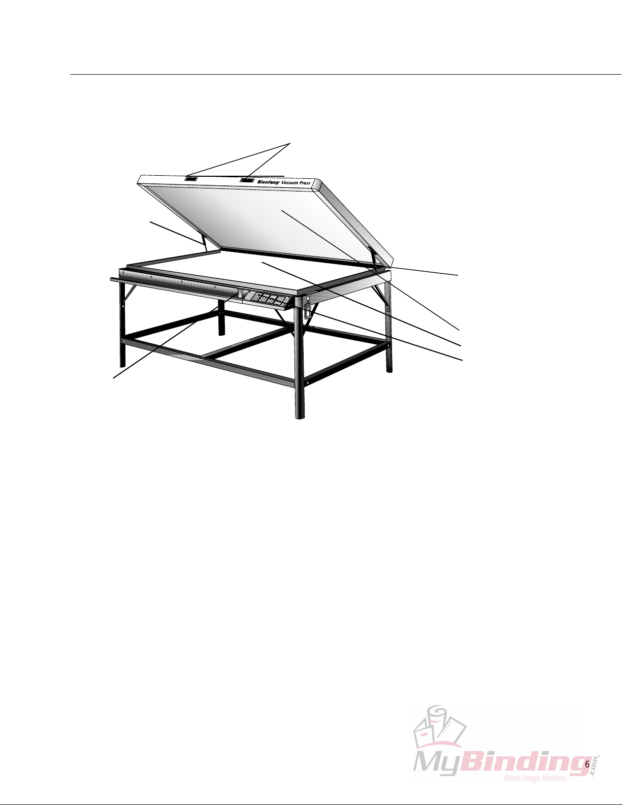
IDENTIFICATION OF CONTROLS
6
Before using the press, prepare a Bienfang®overlay, this
performs the function of keeping the press and work clean
while allowing adhesives to be used oversized without
sticking to the press.
Three types of Release Materials are available:
• Single-Sided Release Paper — a heavy white paper coated
with silicone on one side. This also permits mounting of
the uncoated side to a smooth board to create a reusable
release board (recommended size is Bienfang No. A490 -
42” x 30 yds.).
• Double-Sided Release Paper — a thin paper coated with
silicone on both sides to create two non-stick surfaces
(recommended size is Bienfang No. 934 - 42” x 30 yds.
for 3648H/4468H; Bienfang No. 986 - 50” x 36 yds.
for 5298H).
• Release Board — a thin, smooth board coated with silicone
on both sides. Lays flat to smooth out posters, doesn’t
wrinkle or crease so it lasts longer than release papers
(recommended size is Bienfang No. 938 - 32” x 40",
pack of 5). To be used on top of application only.
One sheet of Bienfang Release Paper should be cut to fit
inside the base of the press (on top of the vent cloth), and
either a second sheet of Release Paper or a Release Board
should be placed over the materials being processed. Never
use a sheet of Release Board under another board or dam-
age to the press platen may occur.
NOTE: Please read the entire manual and fully understand
proper operating procedures before using your press.
Handles
Heat Platen
Vent Cloth
Control Panel
Gas Spring
Vacuum Manifold
Tacking Iron Outlet

7
Turning the Press On
A master power switch/circuit breaker on the side of the
press turns on the display and tacking iron outlet.
Running A Factory-Loaded Program
The Bienfang®Vacuum Press controller has 6 preset
programs that automatically turn on the heat and set the
proper time and temperature. They are handy for frequently
used processes as they save time and eliminate guesswork.
Programs are preset as shown below and can be initiated
by pressing the “Program” key, number 1 through 6 from
the numeric keypad, and “Enter”. Before pressing “Enter”
the display will blink to show the setting, upon pressing
“Enter” the display will stop blinking and the press will
begin to warm up to the temperature setting.
When the press warms up and stabilizes (15-20 minutes)
the program can be run by pressing the “Start/Repeat
Cycle” key which starts the pump and timers. The press
will display the set time and then countdown to (time out).
The controller will also display the vacuum level in the
press and the actual platen temperature.
When the time is up, the press will sound an audible signal
that the cycle is over, but the press will not turn off auto-
matically. Upon hearing the signal, the operator should
press the “Stop” key. The vacuum pump will stop, the
vacuum will release and the press can be opened. The
temperature display will continue to show the actual platen
temperature and timer display will show the best time.
The entire sequence to run Program 1 for dry mounting with
ColorMount or MT5 is:
• Program
• 1
• Enter
• Start/Repeat Cycle
• Stop
NOTE: The press does not turn off automatically because
materials could be accidentally left inside the press with-
out pressure, while they are still hot. This could cause
delaminating or excessive warping of the mounting board.
The press should be turned off and the materials removed
immediately by the operator.
Repeating a Program
To repeat the same program again, just press the
"Start/Repeat Cycle" key
To Run Another Program
Press the “Program” key, the number of the program, and
the “Enter” key. When the temperature has stabilized at the
new setting press the “Start/Repeat Cycle” key to start the
cycle.
• Program
• 2
• Enter
• Start/Repeat Cycle
Warming up the Press
Press the “Heat On” key to warm up the press (when the
heat is turned on the light on the switch will illuminate).
The press will start warming up to 180ºF, the default
setting.
Setting the Temperature
To set a temperature, press the "Set Temp" key, enter the
desired temperature on the numeric keypad, and then
press the "Enter" key. (For example, to set the press
temperature at 190ºF, press "Set Temp", press 190 on the
keypad and press "Enter"). After "Enter" is pressed, the
display will show the actual reading.
Setting the Time
Press the “Set Minutes” key, enter the desired number of
minutes on the numeric keypad, and press “Enter”. (For
example, to set the timer for a 5-minute cycle, press “Set
Minutes”, press 5 on the keypad and press “Enter”.) You
can also set seconds using the “Set Seconds” key in the
same sequence. The set time will display until the cycle
is run.
PROCEDURES FOR USE
Temp. Time Application
Program 1 190ºF 5 mins. ColorMount®/MT5®
Program 2 175ºF 5 mins. Fusion®/BufferMount®
Program 3 150ºF 3 mins. SingleStep®Plus
Program 4 180ºF 3 mins. SingleStep®
Program 5 215ºF 7 mins. Finish Guard®UV (posters)
Program 6 215ºF 9 mins. Finish Guard®UV (photos)

Review Settings
To check the temperature setting, press the “Heat On”
key and the setting will blink on the display for 5 seconds
before reverting back to the actual temperature. While
running a cycle the Time/Temperature settings can be seen
by pressing the “Program” key. After 5 seconds, the display
will revert back to the actual readings.
Changing Settings
To change settings use the “Set” keypad and “Enter” keys.
No changes can be made while a cycle is running.
To Change or Store a Program
To store the settings for a new program (6 programs are
possible), press the “Program” key and any keypad number
from 1 to 6. While the display is blinking, set the desired
time/temperature using the “Set” numeric keypad and
“Enter” keys as usual, then press “Enter” a second time at
the end to save the program. The programs will be remem-
bered even after turning the press off.
To change the settings of an existing program, press
“Program”, the keypad number, and then the appropriate
“Set” key, numeric entry and “Enter”. Press “Enter” a
second time to save the program change.
If a mistake is made while entering or changing a program,
press the “Clear” key to cancel the entry (much like a
calculator). The original program will remain unchanged.
Aborting a Cycle while Running
• To stop in mid-cycle, press “Stop”.
Running a pump without the timer
• To run the pump without the timer (for checking fittings,
etc.), press vacuum “Manual On/Off”.
• Press “Manual On/Off” again to stop the pump.
Changing the display to Metric
If you wish, press the temperature “English Metric” key to
change the display to Celcius or back to Fahrenheit. The
vacuum display can also be set for in/Hg or mm/Hg using
the Vacuum “English/Metric” key. The display will show
whether it is in English or Metric mode by illuminating the
appropriate symbol next to each display.
.
PROCEDURES FOR USE (CONTINUED)
8

RECOMMENDED TIME AND TEMPERATURE SETTING
9
The following suggested settings should give professional-level
results under a variety of conditions. Depending on thickness
and size of board, amount of moisture present, actual line
voltage, and other local conditions you may be able to process
materials faster or you may require longer dwell times. It may
also be possible to lower temperatures slightly (up to 10ºF)
without effecting results if the time is set adequately. Follow
the guidelines in the instruction manual and personal experi-
ence for best results.
MOUNTING
FACTORY PROGRAM SETTINGS
MOUNTING AND LAMINATING
FINISH GUARD-UV
MOUNTING AND LAMINATING AND TEXTURING
EXHIBITEX
NOTE: Allow time for the press temperature to rise from the
initial to the bonding temperature and maintain it for 1-4
minutes (dwell time). With the press at the initial tempera-
ture setting, place the materials inside, set the temperature
at the bonding temperature and quickly close the press
and press the “Start/Repeat Cycle” key. Watch the press
temperature rise and, when it reaches the bonding tempera-
ture, allow an additional 1-4 minutes (depending upon
the size and type of material) processing time. Note the
complete cycle time for future reference.
Material Adhesive Temp. Time Program
Foam Boards ColorMount
®
/MT5 190ºF 4-5 min. 1
Fusion
®
180ºF 4-5 min. 2
BufferMount™
Card Stock ColorMount/MT5 190ºF 5-6 min. 1
Fusion/ 180ºF 5-6 min. 2
BufferMount
Masonite
®
ColorMount/MT5 190ºF 8-10 min. N/A
Fusion/ 180ºF 8-10 min. N/A
BufferMount
Any Spray Off 5 min. N/A
Canvas Fusion 4000 175ºF 4-5 min. 2
Cloth Back CanvasMount™ 170ºF 4-5 min. 2
Temp. Time Application
Program 1 190ºF 5 mins. ColorMount/MT5
Program 2 175ºF 5 mins. Fusion/BufferMount
Program 3 150ºF 3 mins. SingleStep®Plus
Program 4 180ºF 3 mins. SingleStep®
Program 5 215ºF 7 mins. Finish Guard UV (posters)
Program 6 215ºF 9 mins. Finish Guard UV (photos)
Material Adhesive Temp. Time Program
Posters ColorMount/MT5 215ºF 7-10 min. 4
Photos ColorMount 225ºF 9-12 min. 5
Start at low 160-180ºF temperature, load bonding temp. before
closing press.
Material Adhesive Temp. Time Program
Any Fusion/ColorMount 215ºF 8-20 min. 6
Start at low 160-180ºF temperature, load bonding temp. before
closing press.

PERIODIC MAINTENANCE
10
Your Bienfang®Vacuum press has been engineered to
require a minimum level of maintenance. Review the
following to keep the press in prime operating condition
throughout its lifetime.
1. Clean the platen regularly; Bienfang UnStik™ adhesive
releasing solvent or Bienfang Platen Cleaner can be used
to dissolve difficult deposits.
2. Check the vent cloth regularly for proper positioning and
cleanliness. Ensure both vacuum manifolds are fully cov-
ered and clean or replace the vent cloth as necessary when
soiled.
3. Check the vacuum manifolds occasionally for blockages.
Make sure that obstructions, paper and debris are
removed.
4. Check the rubber diaphragm occasionally for abrasions,
cuts, slices and cleanliness; repair or clean as necessary.
5. Check the foam support occasionally for tears, depres-
sions, hard or soft spots, and cleanliness. Repair or clean
as necessary.
6. Check the overall press occasionally for levelness, loose
screws or damaged components. Adjust, tighten or fix as
necessary.
7. Check the vacuum pump occasionally for cleanliness,
dryness and any strange or unusual noises. The vacuum
pump requires no maintenance, however, keeping the
pump clean and dry will result in a longer life.
Hunt Corporation warrants to the original consumer purchaser that each new Bienfang®equipment product which proves
defective in materials or workmanship within the applicable warranty period will be repaired or, at our option, replaced
without charge upon its return, postpaid, as outlined below. The applicable warranty shall be one year from date of
purchase. “Original consumer purchaser” means the person who first purchased the product covered by this warranty
other than for purposes of resale.
Hunt’s liability for breach of any warranty express or implied shall be limited to the repair or replacement, at Hunt’s option,
of the defective item. Hunt shall not be liable for damages, including but not limited to incidental or consequential dam-
ages, arising out of or in connection with the use or performance of any Bienfang product.
To get performance under this warranty, contact Bienfang Technical Support (1-888-240-6021) for assistance or to obtain
a Return Authorization. If it is to be returned, pack the product securely to prevent damage in transit and send the
product, postpaid or freight prepaid, with a description of the defect or malfunction and proof of the date of purchase to
Hunt, Attn: RA Number. Hunt is not responsible for damages from mishandling and abuse in transit, in which case a claim
should be filed with the carrier.
This warranty extends to and is enforceable only by the original consumer purchaser, and only for the period (during
applicable term) during which the product remains in the possession of the original consumer purchaser.
Warranty Department • Hunt Corporation • 2301 Speedball Road • Statesville, NC 28677 • Phone: 1-888-240-6021
LIMITED WARRANTY

TROUBLESHOOTING
11
Symptom Probable Cause Action
No Vacuum Pump, fittings, “solenoid” Perform check below
Levelness see Page 5
Hinge Adjustment see Page 5
Low Vacuum Materials extending Reposition materials
across rubber edges placed in press
Vent Cloth Check position, clean
or replace
Leak in diaphragm Locate and patch or
replace diaphragm
No Heat Not plugged in Check power cord
Power supply off Check circuit breaker
Power Switch off Check position
Heat off Check control
setting
Controller malfunction Contact Bienfang®
Technical Service
Uncontrolled Heat Controller Malfunction Contact Bienfang®
Technical Service
Solid State relay (does press heat
up over temp. even when not
calling for heat)
Bumps, pits Cleanliness Clean platen
Bubbles, no adhesion Improper adhesive Check specifications
Inadequate time Reprocess longer
High moisture level Reprocess longer
Low/uneven pressure See low vacuum
Low/high temperature Check specifications
Checking the Pump and Fittings
To check attachment of the vacuum pump and tubing, open the press and fold the vent cloth forward exposing the two
vacuum manifolds Please a small piece of thin plastic, rubber of similar material (i.e., inner tube, heavy shrink wrap or
plastic film approximately 6" x 6") over each vacuum manifold.
Press the “Manual On/Off” key to run the vacuum pump on and observe the reading on the Vacuum display. If the display
does not read a good vacuum (over 20" Hg), check the vacuum line for leaks. If there are no leaks in the line then have
the pump repaired or replaced. If the vacuum display reads over 20" Hg, then the pump, lines and fittings are all fine.
After completing these checks, press the “Manual On/Off” key to turn the vacuum pump off, remove the pieces of plastic
or rubber from both manifolds and reposition the vent cloth.
www.hunt-corp.com
www.forframersonly.com
© 2003 Hunt Corporation
4777-03
(11/03)
®
Hunt Corporation
Customer Service
P.O. Box 5819
Statesville, NC 28687-5819
For Orders:
Phone: 800-USE-HUNT
Phone: 800-873-4868
Phone: 704-872-9511
For Questions or Technical Assistance:
Phone: 888-240-6021
Fax: 704-871-8671
Hrs: 8:00 a.m.-5:00 p.m. (EST)
Hunt Corporation Canada
690 Gana Court
Mississauga, Ontario
Canada, L5S 1P2
Phone: 905-564-7717
Fax: 905-564-7079
Replacement Part Numbers - Domestic (International)
Description 3648H 4468H 5298H
Pump, Piston
Domestic TS6288126 Kit TS6299126 Kit TS6299126 Kit
International TS56299123 TS6299123 TS6299123
Ball Stud TS1068010 TS1068010 TS1068010
Feet - Leveling TS1103010 TS1103010 TS1103010
Stain Relief, Power Cord
Domestic TS1106045 TS1106045 TS1106045
International TS1106048 TS1106048 TS1106148
Stain Relief, Conduit TS1106046 TS1106046 TS1106046
Union, Tee 3/8” TS1122083 TS1122083 TS1122083
Gas Spring TS1124013 TS1124013 TS1124014
Clip, Gas Spring TS1126015 TS1126015 TS1126015
Plug, Male, Domestic TS12010122 TS1201022 TS1201024
Accessory Plug, Pump TS1202052 TS1202052 TS1202052
Outlet, Tacking Iron
Domestic TS1105024 TS1105024 TS1105024
International TS1105025 TS1105025 TS1105025
Breaker, 2 Pole
Domestic & Intn. TS1308041 TS1308041 TS1308061
Control Board, Assembly
Domestic TS2304093 TS2304093 TS2304093
International TS2304093-1 TS2304093-1 TS2304093-1
R bbon Cable, Interface TS5304026 TS5304026 TS5304026
Insulation TS0511009 TS0511009 TS0511010
New Latch
(Latch Assembly) TS1123013 TS1123013 TS1123013
Replacement Part Numbers - Domestic (International)
Heater(s)
Right TS1202105 TS2302089 TS2302907
Left N/A TS2302089 TS2302097
Center N/A N/A TS2302096
Platen TS5612027 TS5612019 TS5612026
Power Board Assembly
Domestic TS2304092 TS2304092 TS2304092
International TS2304092-1 TS2304092-1 TS2304092-1
Wire Harness
Domestic TS5304027 TS5304027 TS5304053
International TS5304028 TS5304028 TS5304054
Diaphragm Assembly TS6299118 Kit TS6299114 Kit TS6299130KIT
Tubing, 1/4" TS016042 TS016042 TS016042
Tubing, 3/8" TS0509003 TS0509003 TS0509003
Male Elbow, 3/8" Tubing TS1122092 TS1122092 TS1122092
Coupling, F-F TS1122082 TS1122082 TS1122082
Vent Cloth TS5214012 TS5214008 TS5214001
Controller Instructions TB2160C TB2160C TB2160C
Formica Top TS5704016 TS5704014 TS5704013
Sensor, Temperature TS6208075 TS6208075 TS6208075
Relay, SS TS1306026 TS1306026 TS1306028
Solenoid, 12 VDC TS1122087 TS1122087 TS1122087
Flag Terminal, Solenoid TS1238011 TS1238001 TS1238001
Male Elbow, 1/4" Tubing TS1122070 TS1122070 TS1122070
Terminal Block N/A N/A TS1203043
REPLACEMENT PARTS
Other manuals for Vacuum Press 3648H
1
This manual suits for next models
2


