DL35 Owner’s Manual
Part No 792500 Form No F102015D
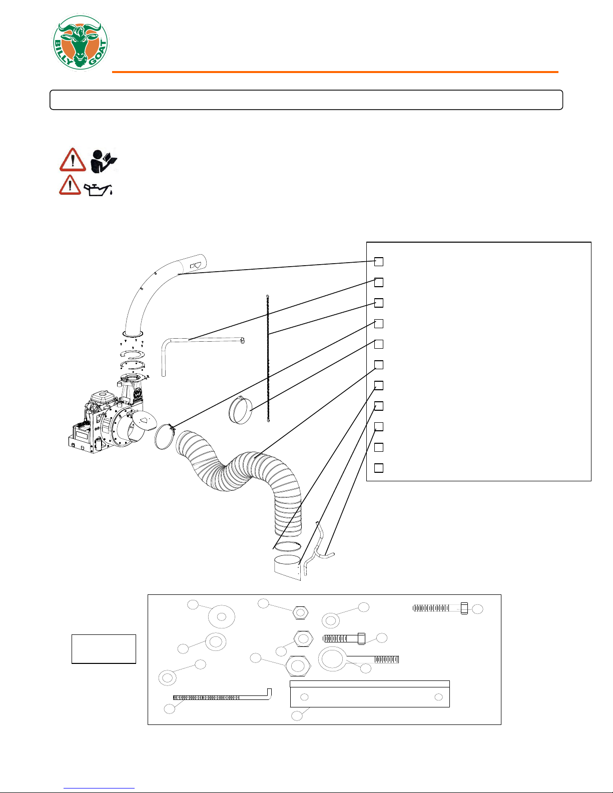
ASSEMBLY
NOTE: Items in ( ) can be referenced in the Parts Illustration and Parts List on pages 11-12.
1. SECURELY ATTACH unit to the bed of a truck or to a trailer, so that the exhaust discharges into an enclosed container.
NOTE: This unit must be securely mounted to the bed of a truck or to a trailer before operating.
2. ATTACH hose to housing intake, using hose clamp (item 12) making sure to place the safety switch under the clamp. Then
place the clamp (item 12) over and around the end of the hose to be attached to the housing. Slide the hose onto the
housing intake and place the shut off switch under the clamp. Make sure the shut off switch is pressed in or the vacuum will
not start, and clamp the hose to the intake. (See page 8 for illustration)
3. ASSEMBLE nozzle handle (item 16), to nozzle (item 15), using screw (item 61), eye bolt (item 57), washers (items 58, 59,
and 91) and lock nuts (items 51 and 60).
4. ATTACH assembled nozzle to hose using hose clamp (item 14). Before tightening hose clamp, position nozzle handle
upward when hose is stretched to prevent twisting. Load on hose assembly during operation.
5. ATTACH the hose boom (item 2) by sliding the boom through the rings on the top of the housing.
6. ASSEMBLE hose band (item 13) around hose and secure chain between the flanges of the hose band using capscrew (item
56), washer (item 48) and lock nut (item 50). Attach the chain (item 21) to the boom and the screw on the hose band. (See
“ADJUSTING HOSE BOOM”on page 7).
7. SECURELY ATTACH exhaust elbow (item 21) capturing both flanges inside the clamp, then firmly tighten the clamp,
securing the elbow to the housing (see “MOUNTING”below).
8. INSTALL a standard 12 volt lawn and garden battery “U1” series (not included) with at least 240 cold cranking amps and a
40 amp hour rating by using battery bracket (item 26), hold down rods (item 27), washers (item 48), and lock nuts (item 50).
9. ATTACH the red battery cable to the + terminal and the black battery cable to –terminal on the battery.
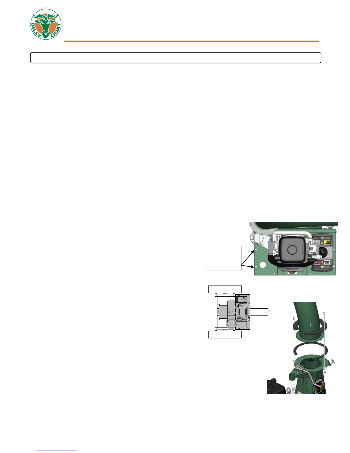
MOUNTING MAIN UNIT
GENERAL:Unit must be securely mounted to a trailer, truck bed, or
other similar surface before use. Do not use this unit in a freestanding
position. Unit is not stable until it has been secured in place.
Secure unit by bolting through the base of the unit and through the
mounting surface using 3/8" dia. bolts, with washers and locking nuts
(see Fig. 1).
MOUNTING: Fig. 2 illustrates the mounting position to the trailer (Billy
Goat Part No. 791133) available from your Billy Goat dealer. The unit is
only mounted one way.
MOUNTING EXHAUST ELBOW (See Fig. 3)
NOTE: this process requires two people, one to support the exhaust
elbow and one to attach plates and hardware.
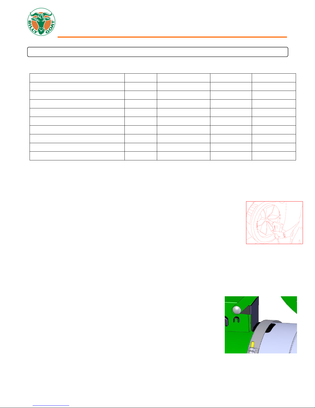
1. Remove the hardware from the clamps (item 70 and 51).
2. Apply good quality grease to the top and bottom of the toothed
plate of the exhaust elbow (Part No. 791114). Also grease top
surface of housing and bottom of clamp plates where the gear
will rotate.
3. Place the exhaust elbow on the chute with the teeth of the flange
against the worm gear and the exhaust holes, aligning.
4. Place the two bottom plates (item 22) on the opposite edges
beside the elbow teeth aligning the holes.
5. Place the top plates (item 23) on top of the lower plates aligning
the holes.
6. Secure the assembly with a plate half on top of the elbow flange
and a plate half on bottom of the housing flange using 6, 1"
carriage bolts and 6 lock nuts (removed hardware in step 1).
Mount these
holes on
both sides