BIOBASIC 210 User manual

BIOBASIC
INSTRUCTIONS FOR USE
Models: 210, 310, 410 & 600

2 | BIOBASIC INSTRUCTIONS FOR USE
Before you proceed
This instructions for use is intended for the following product series:
BIOBASIC
We recommend that you read this instructions for use through thoroughly
before using the cabinet for the rst time. Gram Commercial does not
guarantee safe operation if the cabinet is used for anything other than its
intended use. Contents of the instructions for use can be subject to change
without notice. No part of this instructions for use may be reproduced in
any form without expressed written consent of Gram Commercial. Gram
Commercial guarantees the cabinet under certain warranty conditions. Gram
Commercial is not responsible for any loss or damage of content.
This instructions for use should be considered an integral part of the cabinet
and should be stored close to the cabinet and be easy to access. If the
instructions for use is lost, please refer to your local distributor or Gram
Commercial for a replacement. For current versions of the instructions for use,
please go to www.gram-bioline.com.
Gram BioLine equipment is designed to be used in a system with monitored
additional independent alarms to ensure timely reaction to alarms and thereby
maximum item safety

BIOBASIC INSTRUCTIONS FOR USE | 3
In the event of need for product support, donot hesitate to contact us at:
In the event of technical diculties always contact Gram BioLine technical
support or a Gram BioLine authorized service partner.
Copyright © 2006-2022 Gram BioLine, a division of Gram Commercial, Denmark. All rights
reserved. The content of this publication is owned by Gram BioLine, unless otherwise
noted, and is protected by Danish and international copyright laws and provisions.
Information and images may not be used, copied or transferred without the express
written permission by Gram BioLine.

4 | BIOBASIC INSTRUCTIONS FOR USE
Table of Content
Before you proceed ............................................. 2
Table of Content ................................................ 4
Intended use .................................................... 6
Temperature setpoint range and ambient requirements ......... 6
Symbols used ................................................... 7
Installation ..................................................... 8
Initial setup steps ............................................... 8
Adjusting the base .............................................. 9
Anti tilt bracket ................................................10
Wall mounting .................................................11
Surroundings ..................................................12
Product inspection ............................................13
Voltage free contact ...........................................14
Connecting to power ..........................................16
Equipotential bonding .........................................20
Start up ........................................................22
The digital display controls .....................................22
General introduction to the controller interface ................23
Alarm settings ................................................. 24
Buttons and useful short cuts ..................................25
Operation parameters .........................................26
Error codes ....................................................27
Latching alarms: A2, A3 ........................................27
Sensor oset ..................................................28
Ordinary use ...................................................30
Door gaskets ..................................................32
General info ...................................................33
Responsibility .................................................33
General info ...................................................34
Service ........................................................34

BIOBASIC INSTRUCTIONS FOR USE | 5
Type number plate ............................................35
Access port ....................................................36
Regular maintenance .........................................38
Cleaning .......................................................38
IMPORTANT ....................................................40
Disposal .......................................................41
Datasheet. . . . . . . . . . . . . . . . . . . . . . . . . . . . . . . . . . . . . . . . . . . . . . . . . . . . . . 42
General data: BIOBASIC 210, 310, 410 ..........................42
BIOBASIC RR210 – with solid door ..............................44
BIOBASIC RR210 – with glass door. . . . . . . . . . . . . . . . . . . . . . . . . . . . . . 45
BIOBASIC RR310 – with solid door ..............................46
BIOBASIC RR310 – with glass door. . . . . . . . . . . . . . . . . . . . . . . . . . . . . . 47
BIOBASIC RR410 – with solid door ..............................48
BIOBASIC RR410 – with glass door. . . . . . . . . . . . . . . . . . . . . . . . . . . . . . 49
BIOBASIC RF210 ...............................................50
BIOBASIC RF310 ...............................................51
BIOBASIC RF410 ...............................................52
General data: BIOBASIC 600 ...................................54
BIOBASIC RR600 ............................................... 56
BIOBASIC RF600 ...............................................57
Declaration of Conformity .....................................58
Wiring diagrams ............................................... 59
BIOBASIC RR/RF210, RR/RF310, RR/RF410 ......................59
BIOBASIC RR600 ............................................... 60
BIOBASIC RF600 ...............................................61
Piping diagram ................................................62
Notes ..........................................................64

6 | BIOBASIC INSTRUCTIONS FOR USE
Intended use
BIOBASIC refrigerators (RR) and freezers (RF), are designed and manufactured
to provide general purpose storage of non-critical laboratory items.
The BIOBASIC range complies with EN/IEC 60079-15, covering electrical
apparatus in Category 3, Zone 2 locations where explosive atmospheres may be
present.
Enabling placement of BIOBASIC refrigerators and freezers, in Zone 2 areas
categorised according to EN/IEC 60079-14.
Temperature setpoint range and
ambient requirements
Model + temperature
setpoint range
Minimum ambient
operating temperature
Maximum ambient
operating temperature
BIOBASIC 210, 310, 410
RR with solid door: +2/+15ºC +10ºC +35ºC
RR with glass door: +2/+15ºC +10ºC +32ºC
RF: -25/-5ºC +10ºC +35ºC
BIOBASIC 600
RR: +2/+15ºC +10ºC +43ºC
RF: -25/-5ºC +10ºC +43ºC
The user must ensure that the cabinet is used in accordance with its
intended use. Abnormal use or use conicting with the intended use or
guidelines stipulated in the product documentation can lead to; danger
to patient safety, damage to stored items, damage to cabinet, danger to
user. Gram BIOBASIC equipment is designed to be used in a system with
monitored additional independent alarms to ensure timely reaction to
alarms and thereby maximum item safety.

BIOBASIC INSTRUCTIONS FOR USE | 7
Symbols used
Risk of burning / freezing
Risk of personal injury
Risk of material damage
Risk of electric shock
Hazard
Info
Riskofre/ammable materials
Risk of explosion/explosive materials
ATEX information
8 | BIOBASIC INSTRUCTIONS FOR USE
Installation
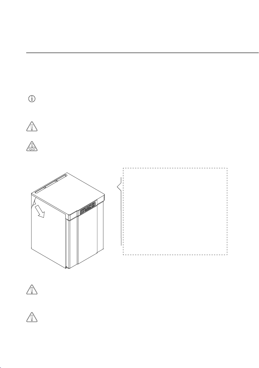
Initial setup steps
The cabinet is shipped with a protective
lm that shall be removed prior to use.
WARNING – POTENTIAL
ELECTROSTATIC CHARGING
HAZARD
Removing protective packaging
and lm may cause electrostatic
discharge. protective packaging and
lm shall not be removed in ATEX
zones.
The cabinet is only allowed to lay down for very short durations (for instance
handling through a doorway). If the cabinet has been laying down, the
cabinet must stand up-right for at least 24 hours prior to use. This enables
oil in the compressors to run back into place.
Avoid placement of the cabinet in a chloric/acidic environment due to risk
of corrosion.
Due to safety and operating considerations, the cabinet must not be used
outdoors. The cabinet should be installed in a dry and suciently ventilated
area. To ensure ecient operation, the cabinet should not be installed in
direct sunlight or close to heat sources.
The cabinet interior must not be exposed to corrosive atmospheres.
Clean the cabinet with a mild soap solution prior to use.

BIOBASIC INSTRUCTIONS FOR USE | 9
Cabinets equipped with legs
should be levelled as shown in the
illustrations to the left.
For cabinets equipped with
castors, the oor must be level
to ensure stable positioning and
safe use. When the cabinet is
positioned, the 2 front castors
should be locked.
Adjusting the base
Cabinets with drawers and/or glass door must be secured to a stable vertical
surface, ensuring that the cabinet cannot tip over when the drawers are drawn
to the outermost position, or the door is open. Brackets for securing the cabinet
are included from the factory.
Find the instructions for the tilt bracket below.
The anti-tilt brackets must be tted when installing the cabinet, ensuring that
the users, surroundings and stored items are not damaged.
10 | BIOBASIC INSTRUCTIONS FOR USE
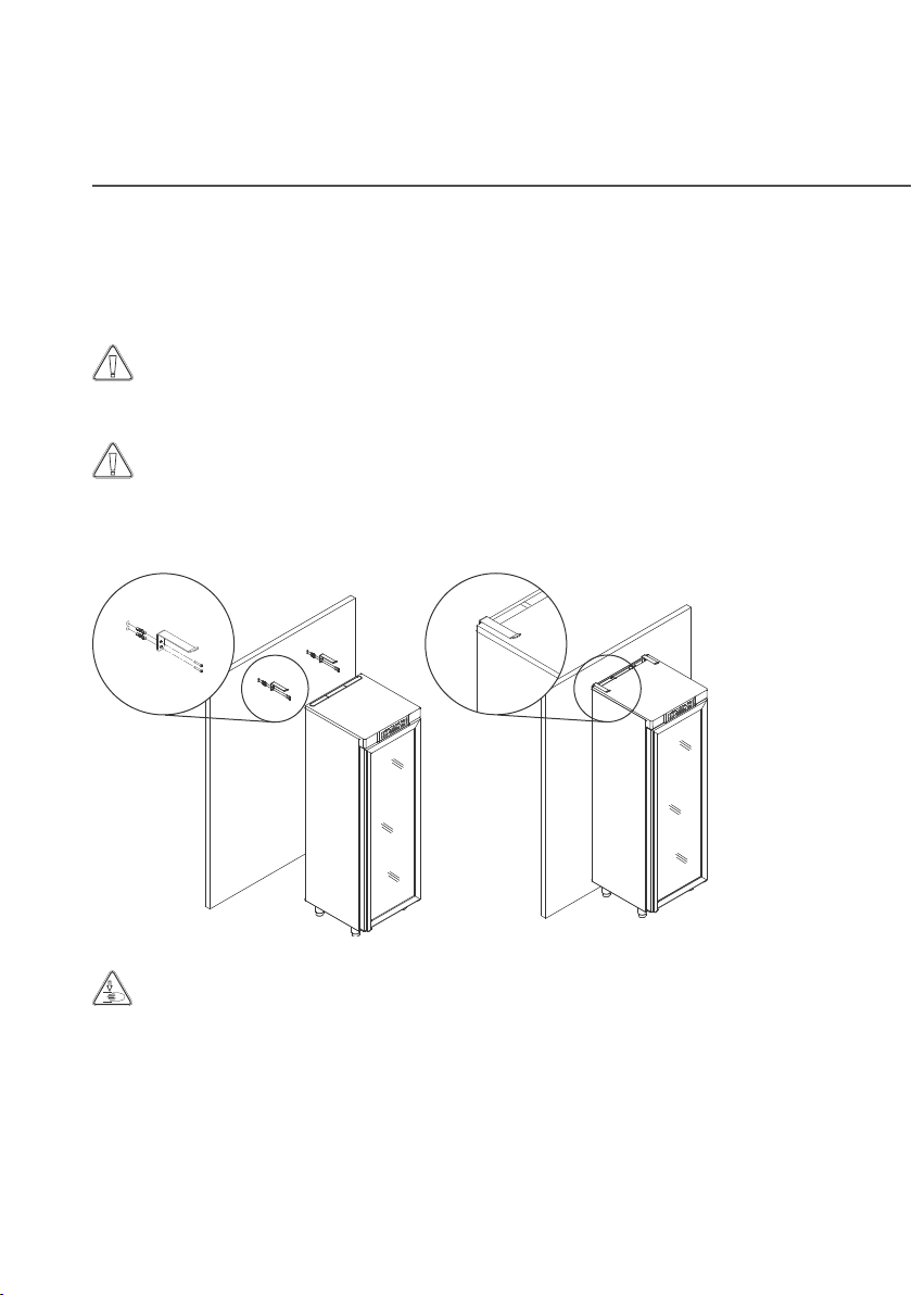
Anti tilt bracket
BIOBASIC INSTRUCTIONS FOR USE | 11
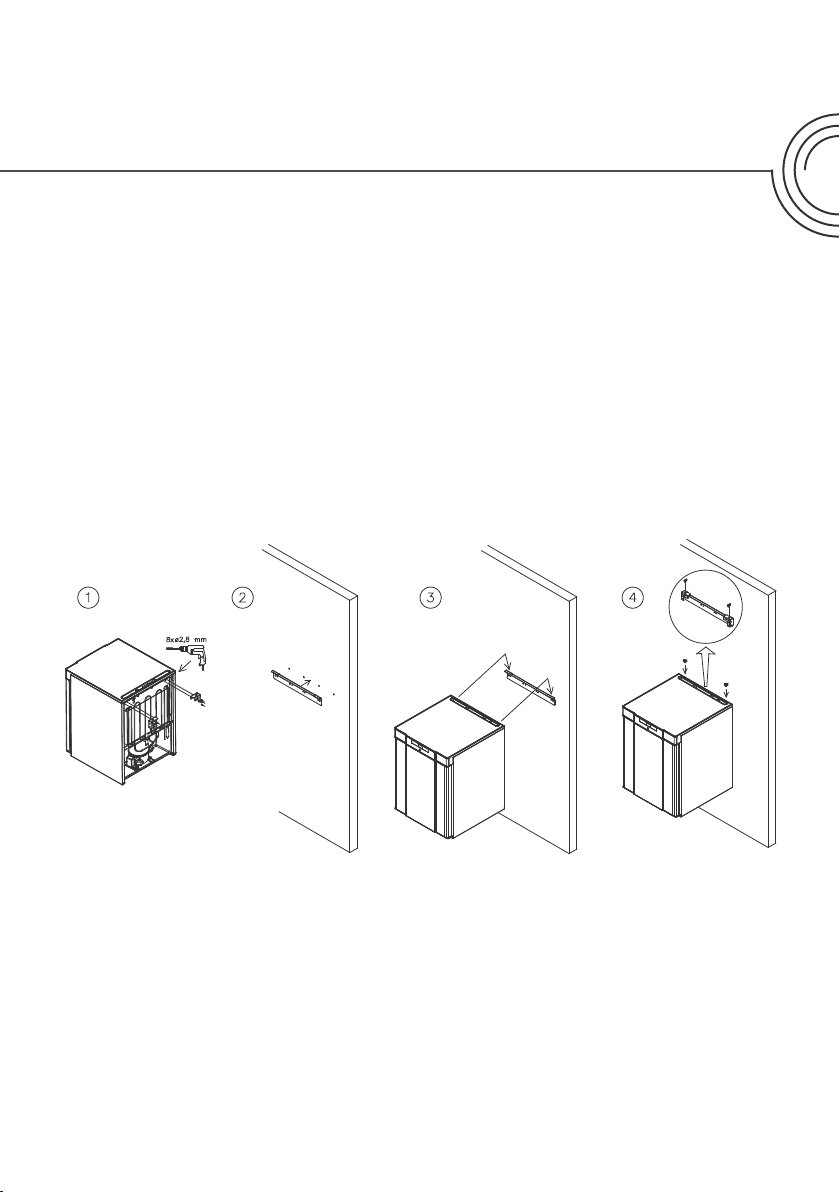
Wall mounting
Wall mounting brackets can be supplied if specied. Allowing the cabinet to be
lifted from the oor.
Find instructions on wall mounting of a BIOBASIC 210 below, the same
procedure applies for mounting 310 and 410.
NB: Applies for 210/310/410 models.

≥30mm
≥15mm
15-75 mm
12 | BIOBASIC INSTRUCTIONS FOR USE
Surroundings
The cabinet must be installed in accordance with the illustrations
below.

BIOBASIC INSTRUCTIONS FOR USE | 13
A visual inspection of the cabinet must be conducted prior to putting the
cabinet into service.
Check the cabinets structural integrity, that door frames and doors don’t
have deformities, gaskets seal properly and the doors sit ush up against
the door frame.
Product inspection

NC
Common
NO
Common
Normally Open (NO)
Normally Open (NC)
NC
Common
NO
Common
NC
Common
NO
Common
+
+NC
NO
NC
The illustration below shows the three connectors for the relay
(e.g. in connecting to CTS or other external monitoring systems).
The three connections are respectively Common, NO (Normally Open) and
NC (Normally Closed).
The moment voltage is applied, the controller draws the relay, this makes it
possible for the controller to respond to both high and low temperature alarms,
door alarms and power failures.
Find instructions on setting the alarms in the controller settings section.
Voltage free contact
Normally closed
circuit (NC)
14 | BIOBASIC INSTRUCTIONS FOR USE

Connection of the voltage free contact should be done by a qualied installer.
Location of the voltage free contact or 210/310/410
Location of the voltage free contact for 600
BIOBASIC INSTRUCTIONS FOR USE | 15

16 | BIOBASIC INSTRUCTIONS FOR USE
When setting up in an ordinary scenario that is not subject to
regulations for EN 60079-15 zone 2:
The appliance may be connected in accordance with applicable local
heavy current regulations.
Note that there are special regulations for products that are in
accordance with EN 60079-15 zone 2 and EN 60079-14: Explosive
atmospheres – Electrical installations design, selection and
erection.
The appliance has been manufactured in accordance with EN 60079-
15: Electrical apparatus for explosive gas atmospheres – Part 15: Type
of protection II 3G Ex ec nC ic IIB Tx Gc. Zone 2 is the applicable zone.
If the appliance is to be installed in a zone 2 environment, specialist
personnel should perform the installation, or be consulted beforehand,
in order to ensure that the appliance is installed in compliance with the
guidelines currently contained in the standard. The cabinet is intended
for connection to alternating current. The connection values for voltage
(V) and frequency (Hz) are given on the type/number plate.
BIOBASIC 210, 310, 410 – The mains terminal is accessed via the preload
cover on the back of the cabinet. Unscrew the preload cover to access
the mains supply terminal. Ensure that the preload cover is reinstalled
after plugging in the power cord. The leaf spring in the preload
cover must engage and preload the plug of the cord as shown in the
illustrations below.
BIOBASIC 600 – The power cord is plugged in the terminal box on the
back of the cabinet. The plug is then xated in place by the hanger that is
built into the terminal box. Please note that the hanger should be tted
tightly around the plug, as shown. In all cases, ensure that the mains
plug is seated completely in the terminal of terminal on the cabinet.
Connecting to power

BIOBASIC INSTRUCTIONS FOR USE | 17
Power cord plugged into 210/310/410 cabinets.
Power cord plugged into 600 cabinet.

18 | BIOBASIC INSTRUCTIONS FOR USE
The appliance must be connected to the external power supply using a suitable
device which mechanically prevents the plug and socket from being separated
unintentionally. The connection must be labelled:
”DO NOT SEPARATE WHEN ENERGIZED”.
Fuses and similar must never be removed or replaced while the appliance
is connected to a power source. The electrical terminal box must never be
opened while the appliance is connected to a power source. The compressor
starting equipment must never be dismantled while the appliance is connected
to a power source. The LED lighting must never be dismantled while the
appliance is connected to a power source. Whenever electrical components are
dismantled or replaced, the appliance must be moved to an area in which there
is no risk of ignition caused by the electrical components or gases contained in
the appliance. Never use the cabinet if the plug is damaged. The cabinet should
be examined by a Gram BioLine authorised service technician in such cases.
Please refer to EN 60079-14: Explosive atmospheres – Electrical installations
design, selection and erection for installation requirements in an ATEX
environment.
In both cases:
Use a three-wire plug, if the power outlet is intended for a three-wire plug,
the lead in green/yellow insulation should be connected to the ground
terminal. Power must be connected via a wall socket. The wall socket should
be easily accessible. All earthing requirements stipulated by the local electricity
authorities must be observed. The cabinet plug and wall socket should then
give correct earthing. If in doubt, contact your local supplier or authorized
electrician.

BIOBASIC INSTRUCTIONS FOR USE | 19
Technical support –
In the event of technical diculties always contact Gram BioLine
technical support or a Gram BioLine authorized service partner.
For Ex environments –
Special conditions for safe use may apply to this product when
installing in an EN 60079-14 environment.
Please see corresponding Ex certicate for specications.
For Ex environments –
Open containers inside the storage chamber may impact the ATEX
zone classication.

20 | BIOBASIC INSTRUCTIONS FOR USE
For installation in ATEX Cat. 3 Zone 2 areas, it is mandatory to have a
equipotential bonding, it is not sucient to use protective earth through
the mains connection.
To secure equipotential bonding of the unit – the mounted external
bonding conductor must be used in accordance with national installation
requirements e.g. EN 60079-14.
• Mounting of the bonding conductor should be done according to the
following illustrations.
• Please nd location for connection facilities on the back of the
cabinet marked with “Attention – Equipotential bonding”.
• The bonding conductor should be at least 4 mm2 gauge.
• Use a ring terminal to ensure adequate bonding.
• Use the supplied M5 machine screw and washer to attach the
bonding conductor to the cabinet. Tighten the machine screw to
3.2 Nm.
Bonding of the cabinet is illustrated on the following page.
Equipotential bonding
This manual suits for next models
3
Table of contents


