BiPOM Electronics MINI-MAX/51-C2 User manual

1
MINI-MAX/51-C2
SingleBoardComputer
Technical Manual
Date: 4March, 2005
Document Revision: 1.02
BiPOMElectronics
16301 Blue Ridge Road, Missouri City, Texas 77489
Telephone: 1-713-283-9970. Fax: 1-281-416-2806
E-mail: info@bipom.com
Web: www.bipom.com

2
©1996-2004 byBiPOMElectronics. All rightsreserved.
MINI-MAX/51-C2 SingleBoardComputerTechnicalManual. No part ofthiswork maybe
reproduced inanymannerwithout written permission ofBiPOMElectronics.
All trademarked namesinthismanualarethe propertyofrespectiveowners.
WARRANTY:
BiPOMElectronics warrantsMINI-MAX/51-C2foraperiod of90 days.Ifthe board
becomesdefectiveduring thisperiod,BiPOMwill atitsoption,replaceorrepairthe
board.Thiswarrantyisvoided if the productissubjected tophysicalabuseoroperated
outside stated electricallimits.BiPOMElectronics will notbe responsiblefordamage to
anyexternaldevicesconnected toMINI-MAX/51-C2.BiPOMElectronics disclaimsall
warrantiesexpress orimplied warrantiesofmerchantabilityand fitness foraparticular
purpose.Inno eventshall BiPOMElectronics be liableforanyindirect, special,
incidentalorconsequentialdamagesinconnection withorarising fromthe useofthis
product. BiPOMElectronics’liabilityislimited tothe purchasepriceofthisproduct.

3
1. Overview
MINI-MAX/51-C2 isageneralpurpose,low-costand highly-expandablemicro-controllersystem.It is
based on the ATMELAT89C51ED2 single-chipFlashmicro-controller. Thismicro-controllerfeatures
•64 KilobytesofIn-SystemRe-programmableDownloadableFlashMemory
•256 bytesofRAM
•1792 bytesofXRAM
•9-sources4-levelInterrupts
•ProgrammableCounterArraywith
-High Speed Output
-Compare/Capture
-PulseWidthModulator
•Three 16 bit Timer/Counters
•ProgrammableEnhanced UART SerialChannel
•SPI SerialInterface
•ProgrammableWatchdog Timer
•32 generalpurposeI/O pins
MINI-MAX/51-C2 boardcomplementsthesefeaturesbyproviding
•512-byteSerialEEPROM(optionalup to128-KilobyteEEPROM)
•RS232 SerialPort connectorforIn-circuit Programming and fordatacommunications
•5-channel10-bit ADC with4.096Vinternaloran externalvoltage referencesource
•10-pinconnectorformatrixand non-matrixkeypads
•Dual-row14-pinLCD connector(withsoftwarecontrast adjustment forLCD)
•20-pinExpansion connectorforperipheralboards( http://www.bipom.com/peripherals.shtm )
•MicrochipPIC16F818 secondary micro-controllertoprovide In-circuit Programming ofthe main
Flashmicro-controllerthrough the RS232 SerialPort and toprovide 5-channel10-bit ADC using the
4.096Vinternaloran externalvoltage referencesource
•On-board5Volt regulator
•6VDC powersupply(Other6to12VDC powersourcescan be used )
•Dimensionsof2.35 X2.40 inches(5.97 X6.10 centimeters).
•Mounting holesof0.138 inches(3.5millimeters)areon fourcorners.
•0°-70°Coperating, -40°-+85°Cstorage temperaturerange.
The Flashmicro-controllercan be seriallyprogrammed whileinthe targetapplication circuit.
Customerscan programthe micro-controllerwiththe mostrecentfirmwareorcustomfirmware.This
function ofthe FLASHmicro-controllersimplifiesnewprogramdevelopmentand debugging.
Downloading ofaprogramtothe micro-controllertypicallytakesfewseconds.
8051/52,BASCOM51,SDCC developmentsystemsbased on Micro-IDE Integrated Development
EnvironmentfromBiPOMElectronics,fullysupportin-systemprogramming and debugging on the
MINI-MAX/51-C2 boardusing the serialport.
AWindows-based program WinLoad isalsoprovided todownload programstothe board.

4
3. Functional Blocks
Figure1showsthe block diagramofthe MINI-MAX/51-C2 system
Figure1
AT89C51ED2
Controller
PIC16F818
controller
Expansion
connector
LCD
connector
22 MHZ
Crystal
24C04A
EEPROM
6…12V
Power
connector
5volt
Regulator
Analog
Input
Connector
Keypad
connector
RS232
connector

5
Micro-controller
MINI-MAX/51-C2 hasan ATMELAT89C51ED2 micro-controller(U2).Micro-controllerportsand power
linesareprovided on a20-pinexpansion busforinterfacing toperipheralsand otherexternalcircuits.
AT89C51ED2 has4portsthat areavailableon the 8051 familyofmicro-controllers: P0…P3.
P0hasopen collectoroutputsthatareavailableon the LCD connectorwith4.7Kpull-up (RB1). P1and
P2aregeneral-purposebi-directionalinput/outputports.Port2isavailableon the keypad connector.
P1and P3areavailableon the expansion connector.P3pinscan eitherbe used asgeneral-purpose
input/outputpinsorhavespecialpurposessuchasasynchronousserialport, interruptinputsand timer
inputs.
Moreinformation on the AT89C51ED2 micro-controllercan be obtained fromATMELweb siteat
http://www.atmel.com.
SecondaryMicro-controller
MINI-MAX/51-C2 hasaMicrochipPIC16F818 micro-controllertoselectan In-circuitProgramming
mode orRun mode ofthe mainFlashmicro-controller.When aRun mode isused,PIC16F818 works
asan I2C slaveperipheraldeviceand can provide 5-channel10-bitADC using the 4.096Vinternalor
an externalvoltage referencesource.
In-SystemProgramming
AT89C51ED2 micro-controllercan be re-programmed remotelyoverthe RS-232 interfaceusing a
second micro-controlleron the board(PIC16F818 ).The in-circuitprogramming featuresimplifies
programdevelopmenton the boardsincedownloading programsfromahostPCtakesonlyfew
seconds. Userprogramscan alsobe debugged overthe serialport.
8051/52,BASCOM51,SDCC developmentsystemsbasedon Micro-IDEIntegratedDevelopment
EnvironmentfromBiPOMElectronics,fullysupportIn-System Programming and debugging on
theMINI-MAX/51-C2 using theserial port.
The on-chipDownloadableFlashof AT89C51ED2 allowsthe programmemory tobe reprogrammed in-
systemthrough RS-232 serialinterface.
The boardoperatesinthe twomodes:
1-RUN mode
2-PROGRAM mode
Run mode isastandardmode when AT89C51ED2 isrunning itsownprogram.
Programmode isaspecialmode when the hardwareconditionsduring the resetpulseforcesthe on-
chipboot loaderexecution.
PCchangesthe boardmode through the RS-232 serialinterfacebyausing ofRTSline.
PIC16F818 ispolling thisline permanentlyand ifthe signalchangesthe levelthen PIC16F818
switchesthe boardmode.
EEPROM
MINI-MAX/51-C2 usesa24C04 (U3)512 byteElectricallyErasableProgrammableRead-Only-Memory
(EEPROM).TypicallythisEEPROMisused forstoring calibration valuesforsensors,customer
identification,serialnumberand otherparameters.ThisEEPROMison asocketand can easilybe
replaced withhighercapacityEEPROM’s(up to128 Kilobytes).

6
Keypad connector
8pinsofAT89C51ED2 areconnected tothe Keypad Connector. Matrixkeypadssuch3by5or4by4
can be connected directlytothe connector. 5Volt and Ground powerlinesarealsoavailableon the
connector.
The keypad connectorcan alsobe used asageneralpurpose8-pininput/output port.
Table1showsthe pinassignmentsforthe Keypad connector.
Keypad Connector(J1)
Name Signal Pin
VCC +5V 10
GND Ground 9
P2.7 In/Out 8
P2.6 In/Out 7
P2.5 In/Out 6
P2.4 In/Out 5
P2.3 In/Out 4
P2.2 In/Out 3
P2.1 In/Out 2
P2.0 In/Out 1
Table1
AsynchronousSerial Port
One asynchronousRS232 serialport isavailableon a9-pinmaleDconnectorJ2. RS232 port can be
used bybothaPCforIn-circuit Programming ofthe T89C51ED2 through PIC16F818 microcontroller
and byT89C51ED2 fordatacommunications.
RTSline isused byan externalhost suchasaPCtoput MINI-MAX/51-C2 inprogramorrun mode.
Therefore, userapplicationsmust not useRTS.
Manyusers try touseHyperTerminal tosend somedatabytestoaMini-Max/51-C2 board.
HyperTerminal forcesaboardtoPROGRAM MODEbyRTSline. AT89C51ED2 programcan not be
executed if HyperTerminal occupiesRS-232 port. WeadvisetouseMicro-IDEterminal windowinstead
of HyperTerminal.
Table2showsthe pinassignmentsforRS232 serialport connector
Serial PortConnector(J2)
Name Signal Pin
- Not Connected (NC) 1
TXD MM51C2 Input 2
RXD MM51C2 Output 3
DTR NC orVcc fromMM51C2 4
GND GND 5
- NC 6
CTS CTS (MM51C2 Output) 7
RTS RTS (MM51C2 Input) 8
- NC 9
Table2

7
LCD Connector
Alphanumeric24 Charactersx2linesLCD suchasBiPOM'sLCD242
(http://www.bipom.com/periph_displays.shtm)oranygenericLCD displaywith4-bit parallelinterface
can be connected directlytoMINI-MAX/51-C2.
LCD Connector(J3)
Signal Pin Pin Signal
P0.7 14 13 P0.6
P0.5 12 11 P0.4
not connected 10 9 not connected
not connected 8 7 P0.3
P0.2 6 5 P0.1
P0.0 4 3 Vee
VCC (+5V) 2 1 GND
Table3
Input/Outputexpansion bus
The 16 controlpinsand 5Voltpowersupplypinsareavailableon the 20-pinconnector(J4)for
interfacing toexisting peripheralboards.Aperipheralboardcan be connected toMINI-MAX/51-C2
eitherasapiggyback daughter-boardusing standoffsorcan be placed awayfromthe MINI-MAX/51-C2
boardusing a20-wireribbon cable(Part#:EXPCABLE-6). Table4showsthe pinassignmentsforthe
connector.
Input/OutputConnector(J4)
Signal Pin Pin Signal
P3.0 20 19 P3.1
P3.2 18 17 P3.3
P3.4 16 15 P3.5
P3.6 14 13 P3.7
P1.0 12 11 P1.1
P1.2 10 9 P1.3
P1.4 8 7 P1.5
P1.6 6 5 P1.7
VCC (+5V) 4 3 GND
VCC (+5V) 2 1 GND
Table4

8
Analog PortTerminal
5-channel10-bit ADC ofMicrochipPIC16F818 micro-controllerisavailableon the 10-pinterminalJ6.
The ADC can operatewitha4.096Vinternaloran externalvoltage referencesource
Table5showsthe pinassignmentsforthe terminal
Analog PortTerminal (J6)
Name Signal Pin
AN0 MM51C2 Analog Input 1
AN1 MM51C2 Analog Input 2
GND GND 3
AN2 Analog Input orExternalVref(-) Input 4
GND GND 5
AN3 Analog Input orExternalVref(+)Input 6
VREF Vref=4.096VfromMM51C2 7
AN4 MM51C2 Analog Input 8
GND GND 9
VCC Vcc fromMM51C2 10
Table5
Power SupplyUnit
MINI-MAX/51-C2 boardcomeswitha6Voltsunregulated DC powersupply.Otherpowersuppliescan
alsobe used.Externalpowersupplyshouldbe abletosupply6to12 VoltsDC atminimum200mA
current(moreifperipheralboardswill be used ).The innerpinof the supplyconnectorispositiveand
the outerring isnegative.
WARNING: Correctpolarityshouldbe observed when applying externalDC supplytoPower
connector.
MINI-MAX/51-C2 hasan on-board5Volt regulatorLM7805 (U5 ).
CAUTION: Depending on the currentrequirementsofthe anyexternalcircuitry suchasperipheral
boardsthatareattached toMINI-MAX/51-C2 and the levelofinput voltage applied, the powerregulator
U1 maydissipateenough heattocauseskininjury upon touch.Contactwiththisregulatorshouldbe
avoided at all times, even afterthe powertocircuit hasbeen switched off.

9
4. Peripherals
MINI-MAX/51-C2 can be connected toawide varietyoflow-cost peripheralboardstoenhanceits
functionality. Somepossibilitiesare:
•Prototyping board(PROTO-1)
•Training Board(TB-1)
•DigitalInput/Output ExpanderBoard(DIO-1)
•Analog (ADC and DAC)Input/Output Boards(DAQ-2543, DAQ-2543-DA1)
•Relayperipheralboards(RELAY-1, RELAY-2, RELAY-4REED)
•RealTimeClock boardswithaMultiMediaCardsocket (RTCboard, MMC/RTCboard)
•Aperipheralboardwithfour7-segment LEDdisplayswithdecimalpoint (LED-1).
Peripheralboardscan eitherbe stacked on top ofMINI-MAX/51-C2 using stand-offsorconnected ina
chainconfiguration using flatribbon cable.Figure2showshowMINI-MAX/51-C2 can be connected to
aperipheralboardinastacked fashion. Figure3showschainconnection.
PERIPHERAL
BOARD
MINI-MAX/51-C
BOARD
STANDOFF
Figure2
MINI-MAX/51-C TRAINING BOARD PROTOTYPING
BOARD
Figure3
Moredetailson BiPOMPeripheralboardsareavailablefrom
http://www.bipom.com/periph_boards.shtm

10
5. Software
8051/52, BASCOM51, and SDCC development systemsprovide manyexamplesthat demonstrate
accessing on-boardperipheralsand performing self-diagnostics.
Pleasedownload anysuitabledevelopment systemfrom
http://www.bipom.com/8051dev.shtm
http://www.bipom.com/bascom51.shtm
http://www.bipom.com/sdcc.shtm
Anyofthe development systemsprovidesMINI-MAX/51-CLoader.
Also, stand-alone loadersareavailabletodownload programcodestothe Mini-Max/51-C2:
WindowsMINI-MAX/51-CCommand-line Loader
DOSMINI-MAX/51-CCommand-line Loader
WinLoad WindowsLoader
Pleasevisit http://www.bipom.com/mm51csoft.shtm

11
6. BoardLayout
Layout of MINI-MAX/51-C2boardisshownbelow:
Expansion
Connector
EEPROM
Socket
Analog
Terminals
AT89C51ED2
CPU
Keypad
Connector
LCD
Connector
Voltage
Regulator
Power
Connector
RS-232
Port
12
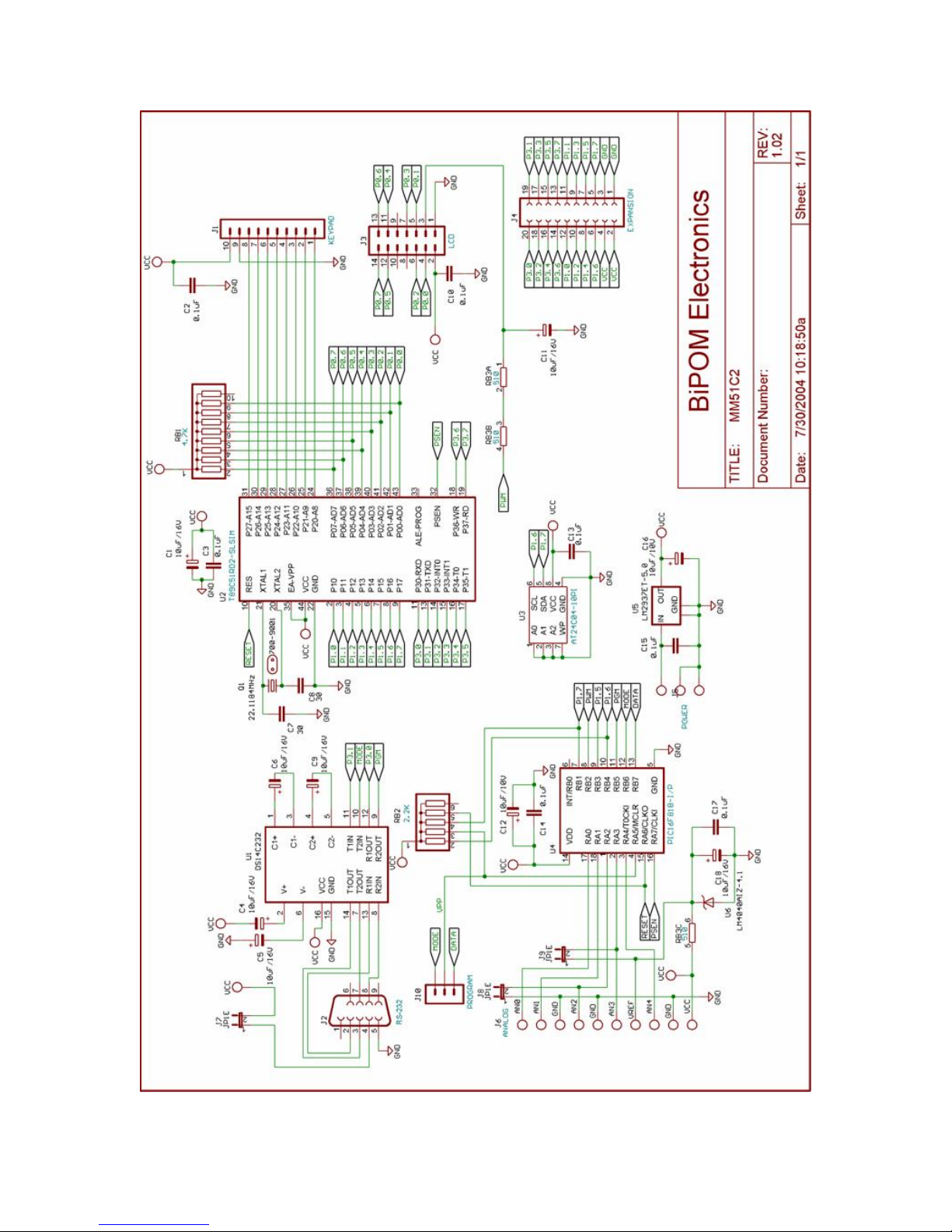
7. Schematics
Table of contents
Other BiPOM Electronics Motherboard manuals


