ECS MCP61M-M3 User manual

Preface
Preface
Copyright
This publication, including all photographs, illustrations and software, is protected
under international copyright laws, with all rights reserved. Neither this manual, nor
any of the material contained herein, may be reproduced without written consent of
the author.
Version 2.0A
Disclaimer
The information in this document is subject to change without notice. The manufac-
turer makes no representations or warranties with respect to the contents hereof and
specifically disclaims any implied warranties of merchantability or fitness for any
particular purpose. The manufacturer reserves the right to revise this publication and
to make changes from time to time in the content hereof without obligation of the
manufacturer to notify any person of such revision or changes.
Federal Communications Commission (FCC)
This equipment has been tested and found to comply with the limits for a Class B
digital device, pursuant to Part 15 of the FCC Rules. These limits are designed to
provide reasonable protection against harmful interference in a residential installa-
tion. This equipment generates, uses, and can radiate radio frequency energy and, if
not installed and used in accordance with the instructions, may cause harmful inter-
ference to radio communications. However, there is no guarantee that interference
will not occur in a particular installation. If this equipment does cause harmful
interference to radio or television reception, which can be determined by turning the
equipment off and on, the user is encouraged to try to correct the interference by one
or more of the following measures:
• Reorient or relocate the receiving antenna.
• Increase the separation between the equipment and the receiver.
• Connect the equipment onto an outlet on a circuit different from that to
which the receiver is connected.
• Consult the dealer or an experienced radio/TV technician for help.
Shielded interconnect cables and a shielded AC power cable must be employed with
this equipment to ensure compliance with the pertinent RF emission limits govern-
ing this device. Changes or modifications not expressly approved by the system’s
manufacturer could void the user’s authority to operate the equipment.
Trademark Recognition
Microsoft, MS-DOS and Windows are registered trademarks of Microsoft Corp.
AMD, Athlon, Sempron and Duron are registered trademarks of AMD Corporation.
Other product names used in this manual are the properties of their respective
owners and are acknowledged.

ii
Preface
Declaration of Conformity
This device complies with part 15 of the FCC rules. Operation is subject to the
following conditions:
• This device may not cause harmful interference, and
• This device must accept any interference received, including interfer-
ence that may cause undesired operation
Canadian Department of Communications
This class B digital apparatus meets all requirements of the Canadian Interference-
causing Equipment Regulations.
Cet appareil numérique de la classe B respecte toutes les exigences du Réglement sur
le matériel brouilieur du Canada.
About the Manual
The manual consists of the following:
Chapter 1
Introducing the Motherboard
Chapter 2
Installing the Motherboard
Chapter 3
UsingBIOS
Chapter 4
Using the Motherboard Software
Describes features of the
motherboard
Go to Hpage 1
Describes installation of
motherboard components
Go to Hpage 7
Provides information on using
the BIOS Setup Utility
Go to Hpage 25
Describes the motherboard soft-
ware
Go to Hpage 45
Chapter 5
SettingUpNVIDIARAIDConfiguration
ProvidesinformationaboutSATA
RAIDSetup
Go to Hpage 49
Chatper 6
SettingUp eJIFFY
Describesthe eJIFFY settingup
Go to Hpage 59
Chatper 7
TroubleShooting
Provides basic troubleshooting
tips
Hpage 69Go to

iii
TT
TT
TABLE OF CONTENTSABLE OF CONTENTS
ABLE OF CONTENTSABLE OF CONTENTS
ABLE OF CONTENTS
Preface i
Chapter 1 1
IntroducingtheMotherboard 1
Introduction......................................................................................1
Feature..............................................................................................2
MotherboardComponents.............................................................4
Chapter 2 77
77
7
Installing the Motherboard 7
SafetyPrecautions...........................................................................7
ChoosingaComputer Case............................................................7
Installingthe Motherboard in a Case............................................7
CheckingJumper Settings...............................................................8
Setting Jumpers...................................................................8
Checking Jumper Settings...................................................9
Jumper Settings...................................................................9
InstallingHardware........................................................................10
Installing the Processor.....................................................10
Installing Memory Modules...............................................12
Expansion Slots.................................................................14
Connecting Optional Devices............................................16
Installinga Hard Disk Drive/CD-ROM/SATAHardDrive...19
Installing a Floppy Diskette Drive....................................20
ConnectingI/O Devices................................................................21
ConnectingCaseComponents.....................................................22
Front Panel Header...........................................................24
Chapter 3 25
UsingBIOS 25
AbouttheSetupUtility................................................................ 25
The Standard Configuration............................................25
Entering the Setup Utility..................................................25
Resetting the Default CMOS Values..................................26
UsingBIOS......................................................................................27
Standard CMOS Features.................................................28
Advanced Setup..................................................................31
Advanced Chipset Setup.....................................................33

iv
Integrated Peripherals.......................................................34
Power Management Setup..................................................36
PnP/PCI Setup....................................................................38
PC Health Status................................................................38
Frequency/Voltage Control.................................................41
Load Default Settings.........................................................42
Supervisor Password.........................................................42
User Password...................................................................43
Save & Exit Setup...............................................................43
Exit Without Saving.............................................................43
Updating the BIOS..............................................................44
Chapter 4 4545
4545
45
UsingtheMotherboardSoftware 45
Aboutthe Software DVD-ROM/CD-ROM.................................45
Auto-installingunderWindows XP/Vista/7..............................45
Running Setup....................................................................46
ManualInstallation........................................................................48
UtilitySoftware Reference............................................................48
Chapter 5 4949
4949
49
SettingUpNVIDIARAIDConfiguration 49
SettingUpaNon-BootableRAIDArray.....................................49
SettingUpaBootableRAIDArray..............................................51
Chapter 6 5959
5959
59
SettingUpeJIFFY 59
Introduction........................................................................................59
Installationand BIOS Setup..........................................................60
Entering eJIFFY......................................................................................63
Features Icons........................................................................................64
Usage FAQ.................................................................................................65
Chapter 7 6969
6969
69
TroubleShooting 69
Startup problems duringassembly............................................69
Startupproblemsafter prolong use.............................................70
Maintenanceandcaretips...........................................................70
Basictrouble shooting flowchart.................................................71

1
Introducing the Motherboard
Chapter 1
Introducing the Motherboard
Introduction
Thank you for choosing the MCP61M-M3 motherboard. This motherboard is a high
performance, enhanced function motherboard that supports socket for AMD
PhenomTM II (socket AM3) processor for high-end business or personal desktop
markets.
This motherboard is based on NVIDIA® ΜCP61 Premium media and communica-
tions processor (MCP) for best desktop platform solution. MCP61P is a single-chip,
highly integrated, high performance HyperTransport peripheral controller, unmatched
by any other single chip-device controller. The memory controller supports DDR3
memory DIMM frequencies of 1333/1066/800. It supports two DDR3 sockets with
maximum memory size of 8 GB*. High resolution graphics via one PCI Express x16
slot, one PCI Express x1 slot, 10 USB 2.0 ports (4 USB ports and 3 USB 2.0 headers
support additional 6 USB ports) and SATA support with RAID function.
There is an advanced full set of I/O ports in the rear panel, including PS/2 mouse and
keyboard connectors, COM, VGA, four USB ports, one optional LPT port, one LAN
port and audio jacks for microphone, line-in and line-out. This motherboard is
designed in a Micro ATX form factor using a four-layer printed circuit board and
measures 244 mm x 214 mm.
* Due to the DRAM maximum size is 2 GB at present, the memory maxi-
mum size we have tested is 4 GB.

2
Introducing the Motherboard
Feature
Processor
HyperTransportTM Technology is a point-to-point link between two devices, it
enables integrated circuits to exchange information at much higher speeds than
currently available interconnect technologies.
• Accommodates AMD PhenomTM II (socket AM3) processor
• Supports up to 2000 MT/s HyperTransportTM (HT) interface Speeds
• High-performance HyperTransport CPU Interface
This motherboard uses a socket AM3 that carries the following features:
• DDR3 1333/1066/800 DDR3 SDRAM with Dual Channel supported
•Accommodates two unbuffered DIMMs
•2 x 240-pin DDR3 DIMM sockets support up to 8 GB
Memory
Audio
• 5.1 Channel High DefinitionAudio Codec
• Exceeds Microsoft Windows Logo Program (WLP) Requirements
• ADCs support 44.1/48k/96k/192k sample rate
• Power Support: Digital: 3.3V; Analog: 5.0V
The onboard Audio provides the following features:
The NVIDIA®MCP61P is a single-chip with proven reliability and performance.
• 1 GHz HyperTransport x16 up and down links to the AMD socket
AM2+/AM2CPUs
• PCI Express 16 lane link interface for external graphics processors
•PCI v2.3 interface at 33 MHz
•Integrated SATA 3.0 Gb/s Host Controller
• Ten USB 2.0 ports supported
• FastATA-133 IDE controller
Chipset
This board supports CPU up to 95W TDP only.
Onboard LAN (optional)
The onboard LAN provides the following features:
• 10/100 full/half duplex operation
• Support MIl and 7-wire SNI (Serial Network Interface)
• IEEE802.3/802.3u compliant
• 1000Base-TIEEE 802.3abCompliant
• 100Base-TXIEEE 802.3uCompliant
• 10Base-TIEEE 802.3Compliant
• IEEE802.3CompliantRGMII
• Supports Auto-Negotiation
• Supports half/full duplex operation
• 0.11um process with very low power consumption

3
Introducing the Motherboard
This motherboard supports Ultra DMA bus mastering with transfer rates of 133/
100/66/33 Mb/s.
: • One PCI Express x16 slot for Graphics Interface
• One PCI Express x1 slot
• Two 32-bit PCI v2.3 compliant slots
• One IDE connector supporting up to two IDE devices
• One floppy disk drive interface
• Four 7-pin SATA connectors
Expansion Options
Integrated I/O
The motherboard comes with the following expansion options:
• Two PS/2 ports for mouse and keyboard
• One serial port
• One optional parallel port
• One VGA port
• Four USB ports
• One LAN port
• Audio jacks for microphone, line-in and line-out
BIOS Firmware
• Power management
• Wake-up alarms
• CPUparameters
• CPUand memorytiming
1. Some hardware specifications and software items are subject to change
without prior notice.
The motherboard has a full set of I/O ports and connectors:
The motherboard uses AMI BIOS that enables users to configure many system
features including the following:
The firmware can also be used to set parameters for different processor clock
speeds.
2. Due to chipset limitation, we recommend that motherboard be oper-
ated in the ambiance between 0 to 50 °C.

4
Introducing the Motherboard
MotherboardComponents

5
Introducing the Motherboard
Table of Motherboard Components
This concludes Chapter 1. The next chapter explains how to install the motherboard.
LABEL COMPONENTS
1. CPU Socket Socket for AMD PhenomTM II (socket AM3) processor
2. CPU_FAN CPU coolingfan connector
3. DDR3_1~2 240-pin DDR3 SDRAM slots
4. CASE Chassis detect header
5. FDD Floppy disk drive connector
6. PWR Standard24-Pin ATX power connector
7. IDE Primary IDE connector
8. SATA1~4 Serial ATA connectors
9. PANEL Front panel Switch/LED header
10. F_USB1~3 Front panel USB headers
11. USBPWR_F Front panel USB power select jumper
12. SPK Speaker header
13. CLR_CMOS Clear CMOS jumper
14. SYS_FAN System cooling fan connector
15. CD_IN Analogaudio input header
16. F_AUDIO Front panel audio header
17. SPDIFO SPDIF out header
18. PCI1~2 32-bit add-on card slots
19. PCIEX1 PCI Express x1 slot
20. PCIEX16 PCI Express x16 graphics card slot
21. ATX12V 4-pin +12Vpower connector
22. USBPWR_R Rear USB/PS2 power select jumper

6
Introducing the Motherboard
Memo

7
Installing the Motherboard
Chapter 2
Installing the Motherboard
SafetyPrecautions
• Follow these safety precautions when installing the motherboard
• Wear a grounding strap attached to a grounded device to avoid dam-
age from static electricity
• Discharge static electricity by touching the metal case of a safely
grounded object before working on the motherboard
• Leave components in the static-proof bags they came in
• Hold all circuit boards by the edges. Do not bend circuit boards
Choosinga ComputerCase
There are many types of computer cases on the market. The motherboard complies
with the specifications for the Micro ATX system case. Firstly, some features on the
motherboard are implemented by cabling connectors on the motherboard to indica-
tors and switches on the system case. Make sure that your case supports all the
features required. Secondly, this motherboard supports one floppy diskette drive and
two enhanced IDE drives. Make sure that your case has sufficient power and space for
all drives that you intend to install.
Most cases have a choice of I/O templates in the rear panel. Make sure that the I/O
template in the case matches the I/O ports installed on the rear edge of the
motherboard.
This motherboard carries an Micro ATX form factor of 244 x 214 mm. Choose a
case that accommodates this form factor.
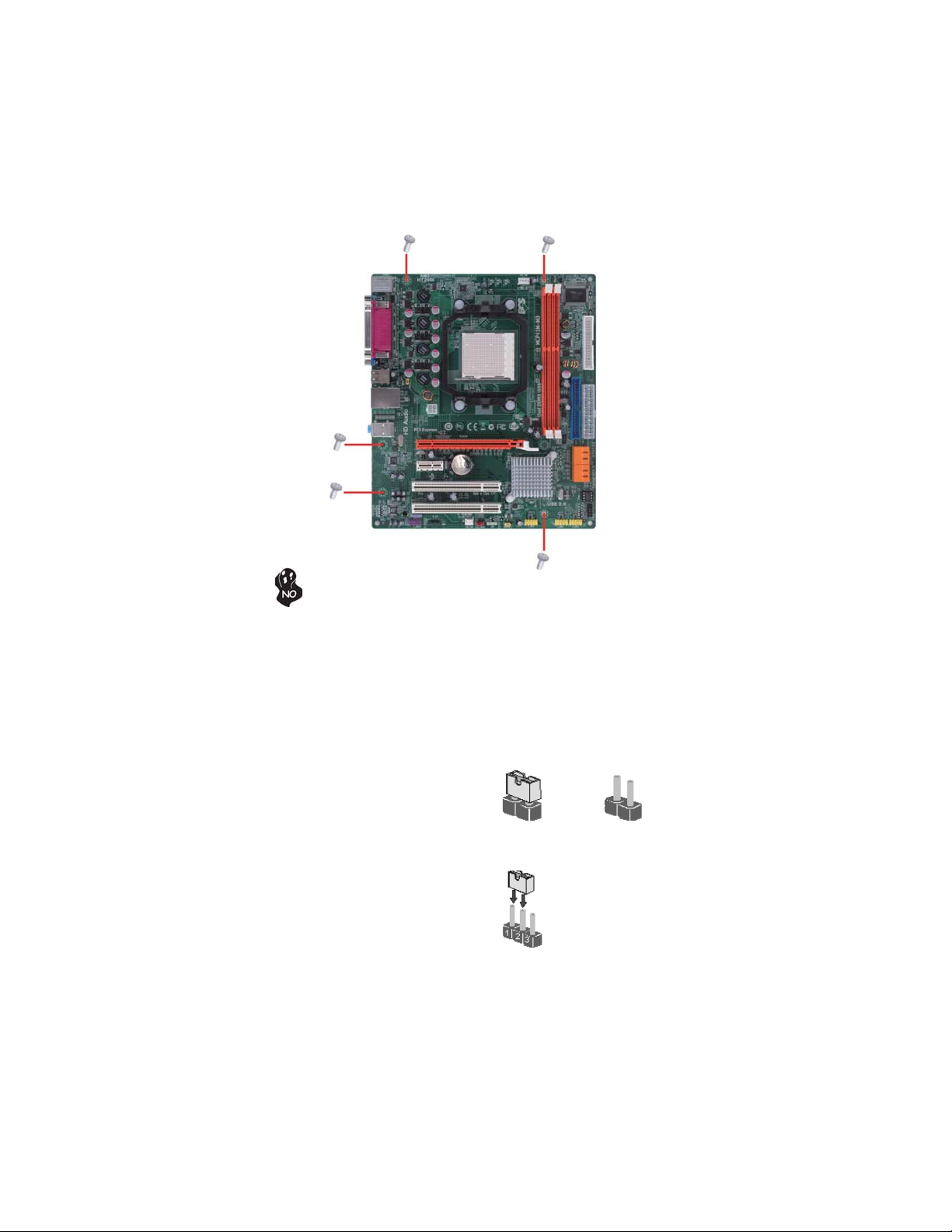
Installingthe Motherboard inaCase
Refer to the following illustration and instructions for installing the motherboard in
a case.
Most system cases have mounting brackets installed in the case, which correspond
the holes in the motherboard. Place the motherboard over the mounting brackets
and secure the motherboard onto the mounting brackets with screws.
Ensure that your case has an I/O template that supports the I/O ports and expansion
slots on your motherboard.
8
Installing the Motherboard
CheckingJumperSettings
This section explains how to set jumpers for correct configuration of the motherboard.
SettingJumpers
Use the motherboard jumpers to set system configuration options. Jumpers with
more than one pin are numbered. When setting the jumpers, ensure that the jumper
caps are placed on the correct pins.
The illustrations show a 2-pin jumper. When
the jumper cap is placed on both pins, the
jumper is SHORT. If you remove the jumper
cap, or place the jumper cap on just one pin,
the jumper is OPEN.
This illustration shows a 3-pin jumper. Pins
1 and 2 are SHORT
SHORT OPEN
Do not over-tighten the screws as this can stress the motherboard.
9
Installing the Motherboard
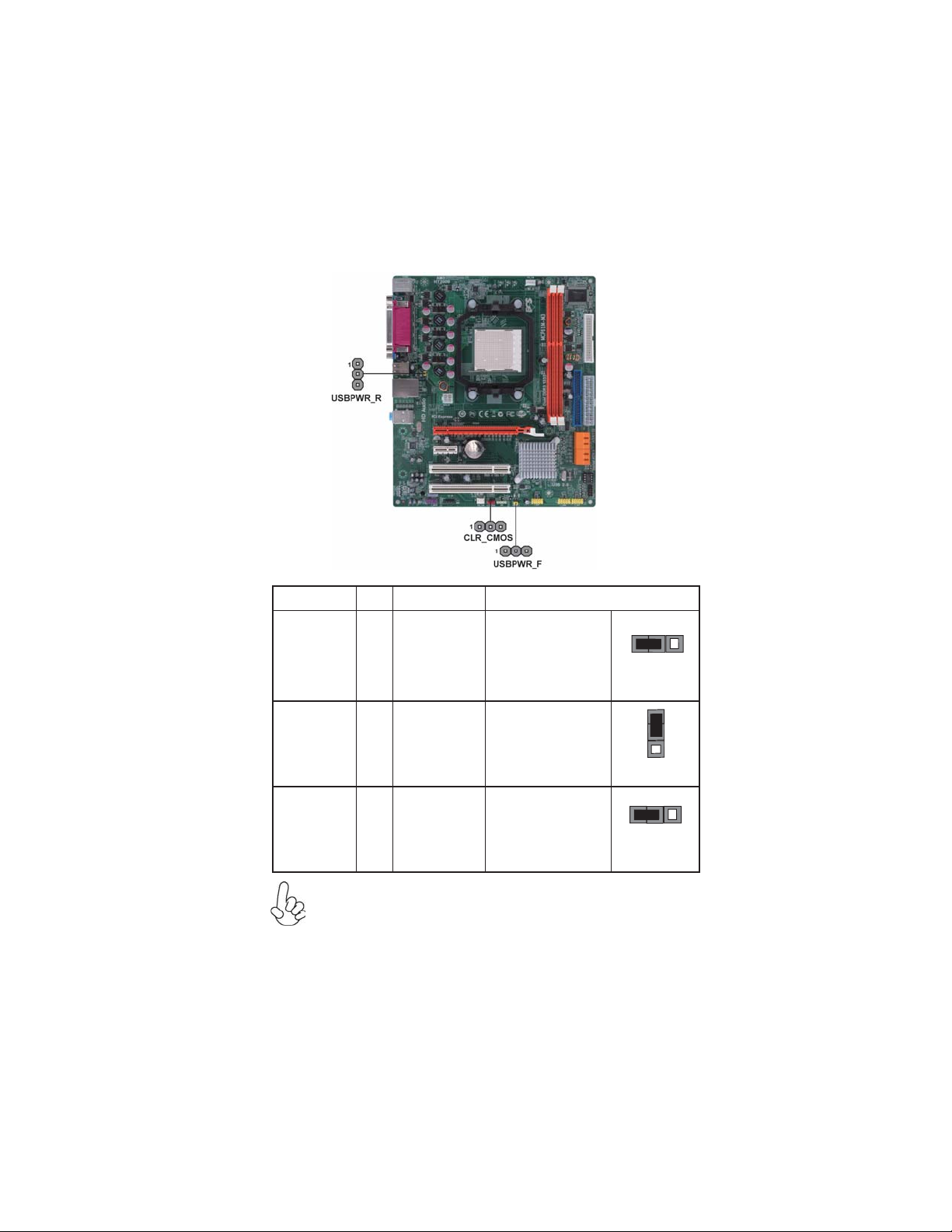
Checking Jumper Settings
The following illustration shows the location of the motherboard jumpers. Pin 1 is
labeled.
JumperSettings
To avoid the system instability after clearing CMOS, we recommend
users to enter the main BIOS setting page to “Load Optimized Defaults”
and then “Save & Exit Setup”.
1.
2. Make sure the power supply provides enough VCC5_DUAL voltage
before selecting the VCC5_DUAL function.
3. It is required that users place the USBPWR_F & USBPWR_R cap onto
2-3 pin rather than 1-2 pin as default if you want to wake up the
computer by USB/PS2 KB/Mouse.
Jumper Type Description Setting (default)
CLR_CMOS 3-pin CLEAR CMOS
1-2: NORMAL
2-3: CLEAR
Before clearing the
CMOS, make sure to
turn the system off.
3-pin
USBPWR_R 1-2: VCC5
2-3: VCC5_DUAL
Rear USB/PS2
Power Select
Jumper
3-pin
USBPWR_F 1-2: VCC5
2-3: VCC5_DUAL
Front Panel
USB Power
Select Jumper USBPWR_F
CLR_CMOS
1
USBPWR_R
1
1

10
Installing the Motherboard
InstallingHardware
Installing the Processor
Caution: When installing a CPU heatsink and cooling fan make sure that
you DO NOT scratch the motherboard or any of the surface-mount resis-
tors with the clip of the cooling fan. If the clip of the cooling fan scrapes
across the motherboard, you may cause serious damage to the motherboard
or its components.
This motherboard has a socket AM3 processor socket. When choosing a processor,
consider the performance requirements of the system. Performance is based on the
processor design, the clock speed and system bus frequency of the processor, and the
quantity of internal cache memory and external cache memory.
Before installing the Processor
This motherboard automatically determines the CPU clock frequency and system
bus frequency for the processor. You may be able to change these settings by making
changes to jumpers on the motherboard, or changing the settings in the system Setup
Utility. We strongly recommend that you do not over-clock processors or other
components to run faster than their rated speed.
On most motherboards, there are small surface-mount resistors near the
processor socket, which may be damaged if the cooling fan is carelessly
installed.
Avoid using cooling fans with sharp edges on the fan casing and the clips.
Also, install the cooling fan in a well-lit work area so that you can clearly
see the motherboard and processor socket.
Warning:
1. Over-clocking components can adversely affect the reliability of the
system and introduce errors into your system. Over-clocking can per-
manently damage the motherboard by generating excess heat in com-
ponents that are run beyond the rated limits.
2. Always remove the AC power by unplugging the power cord from
the power outlet before installing or removing the motherboard or
other hardware components.

11
Installing the Motherboard
CPU Installation Procedure
The following illustration shows CPU installation components.
To achieve better airflow rates and heat dissipation, we suggest that you
use a high quality fan with 4800 rpm at least. CPU fan and heatsink
installation procedures may vary with the type of CPU fan/heatsink sup-
plied. The form and size of fan/heatsink may also vary.
1 Unhookthe locking lever of the CPUsocket. Pull the
locking lever away from the socket and raising it to
the upright position.
2 Match the pin1 corner marked as the beveled edge
on the CPU with the pin1 corner on the socket.
Insert the CPU into the socket. Do not use force.
3 Push the locking lever down and hook it under the
latch on the edge of socket.
4 Apply thermal grease to the top of the CPU.
5 Install the cooling fan/heatsink unit onto the CPU,
and secure them all onto the socket base.
6 Plug the CPU fan power cable into the CPU fan
connector (CPU_FAN) on the motherboard.
12
Installing the Motherboard
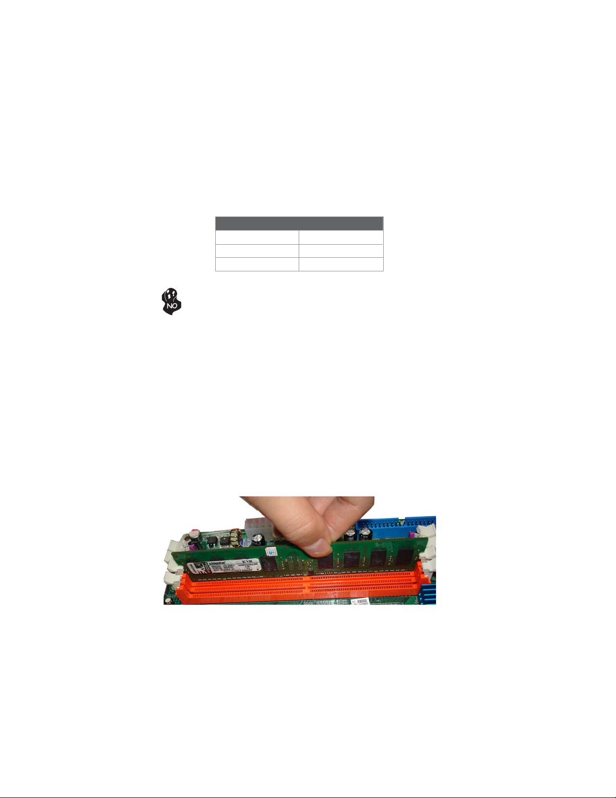
Installation Procedure
Refer to the following to install the memory modules.
1 This motherboard supports unbuffered DDR3 SDRAM only.
2 Push the latches on each side of the DIMM slot down.
3 Align the memory module with the slot. The DIMM slots are keyed with
notches and the DIMMs are keyed with cutouts so that they can only be
installed correctly.
4 Check that the cutouts on the DIMM module edge connector match the
notches in the DIMM slot.
5 Install the DIMM module into the slot and press it firmly down until it
seats correctly. The slot latches are levered upwards and latch on to
the edges of the DIMM.
6 Installany remaining DIMMmodules.
Installing Memory Modules
This motherboard accommodates two 240-pin unbuffered DIMMs and supports DDR3
1333/1066/800 DDR3 SDRAM. You must install at least one module in any of the
two slots. The total memory capacity is up to 8 GB.
Do not remove any memory module from its antistatic packaging until you
are ready to install it on the motherboard. Handle the modules only by
their edges. Do not touch the components or metal parts. Always wear a
grounding strap when you handle the modules.
DDR3 SDRAM memory module table
Memory module Memory Bus
DDR3 1066 533 MHz
DDR3 1333 667 MHz
DDR3 800 400 MHz

13
Installing the Motherboard
Table A: DDR3(memory module) QVL (Qualified Vendor List)
The following DDR3 memory modules have been tested and qualified for use with
this motherboard.
Type Size Vendor Module Name
ELPIDA PC3-8500U-7-00-AP
Hynix HYMT164U64ZNF8-G8 AA
512MB Micron MT4JTF6464AY-1G1B1
A-data M3OSS3H3I3120B5Z
Aeneon AEH760UD00-10FA98X
Corsair CM3X1024-1066C7
HMT112U6AFP8C-G7N0 AA
Hynix HYMT112U64ZNF8-G8 AA
Kingston KVR1066D3N7/1G
MT8JTF12864AY-1G1D1
Micron MT8JTF12864AY-1G1D1
IMSH1GU03A1F1C-10G B2S81427034
Qimonda IMSH1GU03A1F1C-10F B2S81427023
Ramaxel NT5CB128H8AN-DE/1GB
1GB
Samsung Golden Bar M378B2873DZ1-CF8 0818
HYMT125U64ZNF8-G8 AA
Hynix HMT125U6AFP8C-G7N0 AA
MT16JTF25664AY-1G1D1
Micron MT16JTF25664AY-1G1D1
IMSH2GU13A1F1C-10F B3S81427044
Qimonda IMSH2GU13A1F1C-10G B3S81528005
DDR3 1066
2 GB
Samsung M378B5673DZ1-CF8 0842
A-data AD31333001GOU(AD63I1A08)
Aeneon AXH760UD00-13GA98X
Apacer AHU02GFA33C9N1C
Hynix HMT112U6AFP8C-H9N0 AA
KingMax FLFD45F-B8KG9 NAES
Kingston KVR1333D3N9/1G
Micron MT8JTF12864AY-1G4D1
Qimonda IMSH1GU13A1F1C-13H
Ramaxel RMR1810KD48E7F-1333
M378B2873EH1-CH9
1GB
Samsung M378B2873DZ1-CH9
A-data AD31333002GOU(AD63I1B16)
Elixir M2F2G64CB8HA4N-CG 0903.TW
Hynix HMT125U6AFP8C-H9N0 AA
KingMax FLFE85F-B8KG9 NEES
Kingston KVR1333D3N9/2G
Micron MT16JTF25664AY-1G4D1
Qimonda IMSH2GU13A1F1C-13H B3S81124001
DDR3 1333
2 GB
Samsung M378B5673EH1-CH9
14
Installing the Motherboard
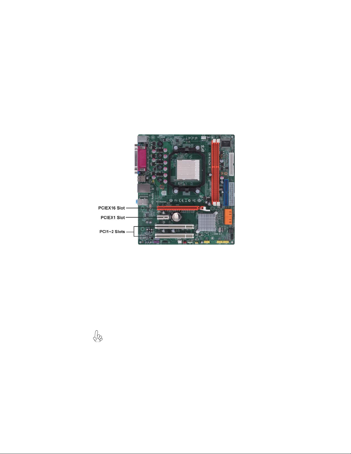
Expansion Slots
InstallingAdd-on Cards
The slots on this motherboard are designed to hold expansion cards and connect
them to the system bus. Expansion slots are a means of adding or enhancing the
motherboard’s features and capabilities. With these efficient facilities, you can
increase the motherboard’s capabilities by adding hardware that performs tasks that
are not part of the basic system.
PCIEX16 Slot The PCI Express x16 slot is used to install an external PCI Express
graphics card that is fully compliant to the PCI Express Base Speci-
fication revision 1.1.
PCI1~2 Slots This motherboard is equipped with two standard PCI slots. PCI stands
for Peripheral Component Interconnect and is a bus standard for
expansion cards, which for the most part, is a supplement of the
older ISA bus standard. The PCI slots on this board are PCI v2.3
compliant.
The PCI Express x1 slot is fully compliant to the PCI Express Base
Specification revision 1.1 as well.
PCIEX1 Slot
Before installing an add-on card, check the documentation for the card
carefully. If the card is not Plug and Play, you may have to manually
configure the card before installation.

15
Installing the Motherboard
Follow these instructions to install an add-on card:
1 Remove a blanking plate from the system case corresponding to the
slot you are going to use.
2 Install the edge connector of the add-on card into the expansion slot.
Ensure that the edge connector is correctly seated in the slot.
3 Secure the metal bracket of the card to the system case with a screw.
For some add-on cards, for example graphics adapters and network adapt-
ers, you have to install drivers and software before you can begin using the
add-on card.

16
Installing the Motherboard
Connecting Optional Devices
Refer to the following for information on connecting the motherboard’s optional
devices:
F_AUDIO:FrontPanel Audio header
This header allows the user to install auxiliary front-oriented microphone and line-
out ports for easier access.
Pin Signal Name Function
1PORT 1L 2 AUD_GND
3PORT 1R 4PRESENCE#
5PORT 2R 6 SENSE1_RETURN
7SENSE_SEND 8KEY
Pin Signal Name
9PORT 2L 10 SENSE2_RETURN
Pin Signal Name
SATA1~4: SerialATA connectors
These connectors are used to support the new Serial ATA devices for the highest date
transfer rates (3.0 Gb/s), simpler disk drive cabling and easier PC assembly. It elimi-
nates limitations of the current Parallel ATA interface. But maintains register com-
patibility and software compatibility with Parallel ATA.
1Ground 2TX+
3TX- 4Ground
5RX- 6RX+
7Ground --
Pin Signal Name Pin Signal Name
Table of contents
Other ECS Motherboard manuals


Popular Motherboard manuals by other brands


REPUBLIC OF GAMERS
REPUBLIC OF GAMERS ROG STRIX B450-F GAMING II quick start guide

Gigabyte
Gigabyte GA-890XA-UD3 user manual

Texas Instruments
Texas Instruments FDC2114 user guide

ON Semiconductor
ON Semiconductor AR0134CSSC00SUEAH3-GEVB user manual

MSI
MSI 7D13-007R quick start guide

Gigabyte
Gigabyte GA-8IG1000MT user manual


