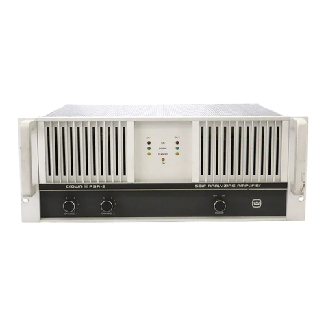
Bittner Audio Basic 200Basic 400Basic 800Basic 1200 User guide

BittnerAudio-Application Handbook Page1
ApplicationHandbook-English
Contents
1. GeneralInformation...................................................................................................... 5
1.1. Copyright&Acknowledgment........................................................................................ 5
1.2. Disclaimer......................................................................................................................... 5
1.3. SafetyInstructions............................................................................................................ 5
1.4. Declaration ofConformity................................................................................................ 6
1.5. EuropeanDirectives......................................................................................................... 6
1.6. WarrantyTerms&Conditions.......................................................................................... 6
1.7. Packing............................................................................................................................. 7
1.8. Air Ventilation&CoolingRequirements.......................................................................... 7
1.9. Installationin Rack........................................................................................................... 7
1.10. Power Connection............................................................................................................ 7
2. TechnicalFeatures........................................................................................................ 8
2.1. AC Power Switch.............................................................................................................. 8
2.2. RemoteSwitching............................................................................................................ 8
2.2.1. Control VoltageXBXVXR4X8X........................................................................ 8
2.2.2. SXL&RS-485 XR4X8X......................................................................................... 8
2.3. LEDIndicators.................................................................................................................. 8
2.4. LevelControl .................................................................................................................... 9
2.4.1. AnalogLevel ControlBASIC XBXV..................................................................... 9
2.4.2. Digital LevelControl 4X8XAX16........................................................................ 9
2.5. AudioConnections........................................................................................................... 9
2.5.1. PhoenixXBXVXR4X8XAX16 .......................................................................... 9
2.5.2. XLR/¼"JackBASIC XR....................................................................................... 10
2.6. Balanced &unbalancedInputs..................................................................................... 10
2.7. Earth / ShieldingBASIC XBXV.................................................................................. 10
2.8. LoudspeakerOutputConnectors.................................................................................. 11
2.8.1. PhoenixXBXVXR4X8X.................................................................................. 11
2.8.2. SPEAKONBASICXR............................................................................................ 11
2.8.3. BindingPostBASIC8XT...................................................................................... 11
2.9. LoudspeakerConnection............................................................................................... 11
2.10. Operation Modes.......................................................................................................... 12
2.10.1. Stereo Mode........................................................................................................... 12
2.10.2. Parallel Mode......................................................................................................... 13
2.10.3. BridgedOperation ................................................................................................. 13
2.10.3.1. Operation ModeSwitchBASIC XBXR...................................................... 13
2.10.3.2. WithoutanOperationModeswitch4X8X................................................. 14
2.11. AliveContactXBXVXR4X8XAX16...................................................................... 14
2.12. DataPortXR4X8XSXLAX16.................................................................................. 14
2.13. Address-IDsXR4X8X................................................................................................ 15
3. SpecificationsoftheDevices...................................................................................... 16
3.1. BASIC Series................................................................................................................... 16
3.1.1. General Information............................................................................................... 16
3.1.2. Features.................................................................................................................. 16
3.1.3. FrontView............................................................................................................... 17
3.1.4. RearView............................................................................................................... 17
3.2. XBSeries........................................................................................................................ 18
3.2.1. General Information............................................................................................... 18
3.2.2. Features.................................................................................................................. 18
3.2.3. FrontView............................................................................................................... 19
3.2.4. RearView............................................................................................................... 19

Page2 BittnerAudio-Application Handbook
3.3. XVSeries......................................................................................................................... 20
3.3.1. General Information............................................................................................... 20
3.3.2. Features.................................................................................................................. 20
3.3.3. FrontView............................................................................................................... 21
3.3.4. RearView................................................................................................................ 21
3.3.5. GroundFaultDetection .......................................................................................... 21
3.4. XRSeries......................................................................................................................... 22
3.4.1. General Information............................................................................................... 22
3.4.2. Features.................................................................................................................. 22
3.4.3. FrontView............................................................................................................... 23
3.4.4. RearView................................................................................................................ 23
3.4.5. SXLDataPort.......................................................................................................... 24
3.4.6. DSPwith Software.................................................................................................. 24
3.4.6.1. Control bySXLWebinterface........................................................................ 24
3.4.6.2. Control byRS-485and PC.............................................................................. 25
3.4.6.2.1. RS-485 Ports................................................................................................. 26
3.4.6.2.2. RS-485 Connector Pin-out ............................................................................ 26
3.4.6.2.3. RS-485 Indicators......................................................................................... 26
3.4.6.2.4. RS-485 Address........................................................................................... 26
3.4.6.2.5. Channelparameters................................................................................... 26
3.4.7. Digital LevelControl ............................................................................................... 27
3.4.8. PagingInput............................................................................................................ 27
3.4.9. MonitorOutput....................................................................................................... 27
3.5. 4XSeries......................................................................................................................... 28
3.5.1. General Information............................................................................................... 28
3.5.2. Features.................................................................................................................. 28
3.5.3. FrontView............................................................................................................... 29
3.5.4. RearView................................................................................................................ 29
3.5.5. SXLDataPort.......................................................................................................... 29
3.6. 8XSeries......................................................................................................................... 30
3.6.1. General Information............................................................................................... 30
3.6.2. Features.................................................................................................................. 30
3.6.3. FrontView............................................................................................................... 31
3.6.4. RearView................................................................................................................ 31
3.6.5. NoiseGate.............................................................................................................. 32
3.6.6. SXLDataPort.......................................................................................................... 32
3.7. SXL-ProgrammableControl Interface.......................................................................... 33
3.7.1. General Information............................................................................................... 33
3.7.2. Features.................................................................................................................. 33
3.7.3. FrontView............................................................................................................... 34
3.7.4. RearView................................................................................................................ 34
3.7.5. StartingUp.............................................................................................................. 34
3.7.5.1. Network Connection....................................................................................... 34
3.7.5.2. Connection oftheAmplifiersand theAX16................................................... 35
3.7.5.3. AddressIDs..................................................................................................... 35
3.7.5.4. SettingsofNetwork Parameters.................................................................... 36
3.7.6. LEDIndicators......................................................................................................... 36
3.7.7. Ports........................................................................................................................ 37
3.7.7.1. LogicalInputs.................................................................................................. 37
3.7.7.2. Relayoutputs.................................................................................................. 37
3.7.7.3. EmergencyPagingBus................................................................................... 37
3.7.7.4. MonitorBus..................................................................................................... 38
3.7.8. Operation ............................................................................................................... 39
3.7.8.1. Manual operation .......................................................................................... 39
3.7.8.1.1. Menus&Parameters................................................................................... 39
3.7.8.1.2. EntryModes&StatusInformation .............................................................. 40
3.7.8.1.3. Savingand LoadingofConfigurations....................................................... 41

BittnerAudio-Application Handbook Page3
3.7.8.2. WebInterface................................................................................................. 41
3.7.8.2.1. Main Page................................................................................................... 42
3.7.8.2.2. Amplifier&ChannelSettings(incl.DSP).................................................... 42
3.7.8.2.3. Error Matrixand RelayControl................................................................... 44
3.7.8.2.3.1. Error Matrix........................................................................................... 44
3.7.8.2.3.2. RelayControl........................................................................................ 44
3.7.8.2.3.3. TimeControlledTasks.......................................................................... 44
3.7.8.2.4. Configurations............................................................................................. 45
3.7.8.2.5. Special Settings.......................................................................................... 46
3.7.8.2.5.1. Deviceand ChannelLabels................................................................ 46
3.7.8.2.5.2. Login..................................................................................................... 46
3.7.8.2.5.3. Syslog................................................................................................... 46
3.7.8.2.5.4. SMTP..................................................................................................... 47
3.7.8.2.5.5. SXLHomeAddress .............................................................................. 47
3.7.8.2.5.6. Re-start................................................................................................. 47
3.7.8.2.6. AX16IntelligentAmplifierSwitch................................................................ 47
3.7.8.2.7. Logbook...................................................................................................... 48
3.7.9. SpecialFunctions.................................................................................................... 49
3.7.9.1. ConfigurationSwitchingviatheLogicInputs................................................ 49
3.7.9.2. Error Matrix..................................................................................................... 50
3.7.9.3. LineMonitoring............................................................................................... 50
3.7.9.4. Error Acknowledgment.................................................................................. 51
3.7.9.5. BackupSwitching........................................................................................... 52
3.7.9.6. PermanentBackupofOperationModes ...................................................... 52
3.7.10. Software&Files...................................................................................................... 53
3.7.10.1. BasicFunctions............................................................................................... 53
3.7.10.1.1. TFTP ............................................................................................................. 53
3.7.10.1.2. MS-DOS....................................................................................................... 54
3.7.10.2. Firmware........................................................................................................ 55
3.7.10.3. WebInterface................................................................................................. 56
3.7.10.4. BackupofSXLfiles ......................................................................................... 56
3.7.10.4.1. GlobalSXLSettings.................................................................................... 56
3.7.10.4.2. SXLConfigurations...................................................................................... 56
3.7.10.4.3. DSPConfigurations..................................................................................... 56
3.7.10.4.4. Logbook...................................................................................................... 57
3.7.10.5. Tips&Tricks.................................................................................................... 57
3.7.11. AmplifierFunctions-Overview.............................................................................. 58
3.7.12. Error Codes............................................................................................................. 59
3.8. AX16-IntelligentAmplifierSwitch................................................................................. 60
3.8.1. General Information............................................................................................... 60
3.8.2. Features.................................................................................................................. 60
3.8.3. FrontView............................................................................................................... 61
3.8.4. RearView............................................................................................................... 61
3.8.5. LEDIndicators......................................................................................................... 62
3.8.6. Starting................................................................................................................... 63
3.8.6.1. Operation Modes........................................................................................... 63
3.8.6.1.1. SwitchingModes........................................................................................ 63
3.8.6.1.2. Connected Amps........................................................................................ 63
3.8.6.1.3. LogicofAliveContact................................................................................. 63
3.8.6.1.4. ControlModes ............................................................................................ 64
3.8.6.2. Connection ofAmplifier ................................................................................. 64
3.8.6.2.1. Signaland AmplifierInputs........................................................................ 64
3.8.6.2.2. Amplifier Outputsand Loudspeakers........................................................ 65
3.8.6.2.3. ALIVEcontactsoftheamplifier................................................................... 65
3.8.6.3. DataPort......................................................................................................... 65
3.8.7. LevelControl........................................................................................................... 66
3.8.8. ALIVEand ACTIVEContacts................................................................................... 66

Page4 BittnerAudio-Application Handbook
3.9. XTSeries ......................................................................................................................... 67
3.9.1. General Information............................................................................................... 67
3.9.2. Connections............................................................................................................ 67
3.10. 8XTSeries ....................................................................................................................... 68
3.10.1. General Information............................................................................................... 68
3.10.2. FrontView............................................................................................................... 68
3.10.3. RearView................................................................................................................ 68
4. GeneralTechnicalInformation................................................................................... 69
4.1. Decibel........................................................................................................................... 69
4.2. 100 V............................................................................................................................... 69
4.3. UsefulThings.................................................................................................................. 70
5. TechnicalData............................................................................................................. 73
6. Troubleshooting........................................................................................................... 75

BittnerAudio-Application Handbook Page5
1. General Information
1.1. Copyright&Acknowledgment
©2007Bittner Audio.AllRightsReserved.
BittnerAudio reservesspecification privilegesInformationinthismanualissubjecttochange
withoutnotice.
Congratulationsand thank youfor buyingBittnerAudio.
1.2. Disclaimer
In nocaseshall BittnerAudiobeliablefor anyspecial,incidental,or consequentialdamagesto
loudspeakers, amplifiers,or otherequipmentifsuchdamagesarebasedupon negligenceduring
installationor operation. Such damagesinclude, but arenotlimitedto, lossofprofitsor anyother
lossofpropertyofthepurchaser.In casethecontractualliabilityofBittner Audioisexcludedor
limited, thisalsoappliestothepersonalliabilityofemployees,representatives, assistantsand
otherauxiliarypersons.
Shouldanypartoftheequipmentshowdefectsin materialsand workmanship,including
transportdamage, thecustomerisaskedtocomplain toBittner Audio.Failureofcomplaint,
however, hasnoconsequencesfor yourlegal claims.
BittnerAudiopointsoutthatallspecificationsmaybesubjecttochangewithoutnoticeand that
liabilityfor incorrect, incompleteor outdated informationisexcluded. Thiswarrantydoesnot
affectyourstatutoryrights.
International:Pleasecontactyoursupplierforspecificregionalinformation, asrightsand
disclaimersmayvaryfrom countrytocountry.
1.3. SafetyInstructions
CAUTION!
Toreducetheriskofelectricalshock,donotremovethecover. Thereareno user
serviceablepartsinside,refer allservicingtoqualifiedpersonnel. Replacefuses onlywith
sametype. AvoiddamagingtheACplugor cord.Damagemaypotentiallycausea
shockhazard.TheunitshouldonlybeconnectedtoanACpowersupplyofthecorrect
voltage.
Neverisolatetheground oftheAC powercord (thenon-fused earthed protective
conductor)to eliminatehum-problems.
Toreducetheriskoffireorelectricalshock, donotexposethisapplianceto rainor
moistureanddon’tuseitindampareasornearwater.
Theunitmustbeadaptedslowlytoextremetemperaturechanges.Theseextreme
changescancause insidemoisturedevelopmentthatcan causefailureand/or electrical
shock.
Thepowerfusesarelocated onthebackpaneloftheamplifier and maybeaccessed
from theoutside. Useonlytheappropriatefusesaslabeled.
Though allBittnerAudio devicesarequitesimpletooperateand arecoveredbyasolid
steelchassis, improperusemaybedangerous.Someoftheunitscan putout veryhigh
voltagesand asizablecurrentatfrequenciesupto30kHz.
Alwaysusesafeoperatingtechniques! Incompetentandimproperservicingwill voidthe
warranty.

Page6 BittnerAudio-Application Handbook
1.4. DeclarationofConformity
BittnerAudio herebydeclaresthatthisproductisin accordancewiththefollowingstandards:
˜LowVoltageDirective73/23/EEC, lastamendedby93/68/EEC
˜EMCDirective89/336/EEC, amended by92/31/EECand93/68/EEC
˜EN60065: 2002
˜EN55013: 2001 +A1:2003+A2: 2006
˜EN55020: 2002 +A1:2003+A2: 2005
˜EN61000-3-2:2006
˜EN61000-3-3:1995+A1: 2001 +A2:2006
˜EN55103-1:1996
˜EN55103-2:1996
1.5. EuropeanDirectives
BittnerAudioalsodeclaresthatthisproductisin compliancewiththerequirementsofthe
EuropeanDirectives2002/96/EC (WEEE)and2002/95/EC(RoHS).
TheprimaryaimoftheWEEEDirectiveand RoHSDirectiveisto reducetheimpactofdisposalof
electrical and electronicequipmentatend-of-life. TheWEEE Directiveaimsto reducetheamount
ofWEEEsentfor disposalto landfill orincineration byrequiringproducerstoarrangefor collection
andrecycling.TheRoHS Directivebanstheuseofcertainheavymetalsand brominatesflame
retardantstoreducetheenvironmental impact.
1.6. WarrantyTerms&Conditions
BittnerAudio warrantsthisproducttobefree from defectsin materialsandworkmanship.
Shouldanypartofthisequipmentbedefective, theManufactureragreesto repair or replaceany
defectivepartfree ofcharge(excepttransportation charges)for aperiodofthreeyearsfromthe
dateoftheoriginalpurchase.
Warrantyserviceiseffectiveand availabletotheoriginal purchaser only.
Toobtain serviceunderthiswarranty,theproductmust, ondiscoveryofthedefect, beproperly
packedandshippedto thenearestBittnerAudiodealer. Thepartyrequestingservicemust
provideproofoforiginal ownershipanddateofpurchaseoftheproduct.
Ifthewarrantyisvalid,BittnerAudio will,withoutchargefor partsorlabor,eitherrepairor
replacethedefectiveparts. Withoutavalidwarranty,theentirecostoftherepairisthe
responsibilityoftheproduct’sowner.
Thewarrantydoesnotcoverdefectsor repairsneededasaresultof:
1.Damagecausedbyabuse,accident,or negligence.
2.Damagecausedbyanytampering, alteration,or modification oftheproductorits
components.
3.Damagecausedbyfailuretomaintain and operatetheproductinstrictaccordanceto the
written instruction ofthisoperatingmanual.
4.Damagecausedbyrepairsor attemptedrepairsbyunauthorized persons.
5.Damagecausedbyfire,water and other naturalevents.
6.Damagecausedbyoperationon impropervoltages.

BittnerAudio-Application Handbook Page7
1.7. Packing
Uponunpacking,pleaseinspecttheproduct. Ifyoufindanydamage,notifyyoursupplier
immediately.Besureto savethecarton andall packingmaterialsincaseyouhavetosendthe
producttothesupplier.
Pleaseuseonlytheoriginalfactorypacking. Iftheshipmentcartonisunavailable,contactBittner
AudioInternational GmbH(www.bittner-audio.com) toobtain areplacement.
1.8. AirVentilation&CoolingRequirements
Theamplifierisequippedwith aforcedair-coolingsystemwith variablespeedand temperature
controlledfanstoguaranteelowoperatingtemperatureand minimal ventilation noise. Theair
flowtakesplacefromthereartothefrontoftheamplifier.Theair-pullingfansareinstalled onthe
backsideoftheunit. Theairflowisalwaysfromthefrontto therear side.
Incase aheatsink becomestoo hot,thetemperaturesensor openstherespectiveoutput relay,
disconnectingtheoutput loadfromtheparticularchannel.In casethepower transformergets
overheated, adifferentsensor causestheoutputrelayson all channelstoopen andto interrupt
theoutputs.Aftercoolingdowntoan appropriateoperatingtemperatureleveltherelaycontacts
areclosedagainautomatically.
Itisimportanttohaveadequateairventilation spacebehindtheamplifierto allowaproperair
flow.In casetheamplifierismounted insideaclosedrack,donotcoverthefrontoftherackwith
doors.Ifusingrackswithaclosedbackside,use fansontherearrackpanel. BittnerAudio
recommendsoneopenrackspacefor every3mounted power amplifiers.
1.9. InstallationinRack
All deviceswillmountin standard19-inchrackshavingsufficientdepth and shouldbemounted
withfourstandardrackbolts.Toavoid thedeformation ofthechassisitisrecommended tomount
heavyunitsonhorizontal brackets.
Pleaseensureasufficientairflow.In thecase,closedracksarebeingused rack-fansshouldbe
used.For larger installationsoneopenrackspace(1RU)for every3mounted power amplifiers
should beprovided.
1.10. PowerConnection
Thepoweramplifier mustbeconnectedonlywiththeattachedthree-wiresafetypower
cordwith protectiveconductor (non-fusedearthedconductor).
Thisamplifierismadefor usewith themainsvoltagelabeledon thebackoftheamplifier
only.Checkthelabelon theback paneloftheamplifierfortheappropriatevoltage.
Makesurethevoltageofyourmainsoutletiscorrect.Thepower voltageisfactorysetas
labeledon thebackpanel and cannotbechangedafterwards.Damagecausedby
connectingtheamplifierto improperAC voltagevoidsthewarranty.
NEVERisolatethegroundoftheACpower cords(thenon-fusedearthedprotective
conductor)to eliminatehum-problems.
Alwaysturn offand disconnecttheamplifierfrom themainsvoltagebeforemakingany
audioconnections. Asaprecaution, turntheaudioattenuatorson thefrontpaneldown
duringpoweringup.
Thepowerfusesarelocated onthebackpaneloftheamplifier and canbeaccessed
from theoutside. Useonlytheappropriatefusesaslabeled.
After properlymountingand connectingtheACcordandtheaudioconnections,theunit
can beswitchedon.

Page8 BittnerAudio-Application Handbook
2. Technical Features
2.1. ACPowerSwitch
Themainpowerswitch islocated ontherear paneloftheunit.Iftheremoteswitchingoptionis
notbeingused,thedevicemustbeswitched onand offwiththemain powerswitch. Tousethe
remotepowerswitchingoption,themain powerswitch mustbeturnedoff.
2.2. RemoteSwitching
2.2.1. ControlVoltage XBXV XR4X8X
ThePHOENIXterminalblock (see picturebelow)isused toremotelypoweruptheamplifierwitha
control voltage(12 VDC 80mA). Terminal IN isusedasthecontrolvoltageinput.Feedingthese
terminalswith thecontrol voltagewillswitchtheamplifier on.
After adelayofonesecondthecontrol voltagewill appearon theterminalslabeled OUT ofthe
PHOENIXterminalblock.The OUT terminalsmaybeconnectedtotheterminals IN ofthenext
amplifierfor sequentialpowerswitching.Upto16unitsmaybedaisy-chained thisway.
Thecontrol voltagemustbeapplieduntil thelastamplifierin thedaisy-chain isbeingswitched
on. BysupplyingtheinvertedDCcontrol voltagetoterminal IN,all connected amplifierswillbe
switched off.
RemoteSwitchingPHOENIXConnector:
IN+ AmplifierSwitchingPOSITIVEterminal
IN- AmplifierSwitchingNEGATIVE terminal
OUT+
Control VoltageoutputforsequentialswitchingPOSITIVEterminal
OUT- Control VoltageoutputforsequentialswitchingNEGATIVE terminal
2.2.2. SXL&RS-485 XR4X8X
Ifthedeviceisconnected toaBittner AudioSXLor viatheRS-485interfacetoaPC (XRonly),the
unitcanberemotelyswitched onandoffatanytime.
2.3. LEDIndicators
Theamplifiersareequippedwith4LEDsforeachamplifierchannel:
CLIP,SIGNAL, PROTECTandPOWER
LED Color Function
POWER green
Theamplifierispoweredup
CLIP red Theinput isoverloaded.TheLEDstartsilluminatingassoon asthesignalis
0.5dB underfull power.
SIGNAL green
Thesignalreachestheoutput stageoftheamplifier.
PROTECT
Red ThisLEDwill lightupassoonaprotection circuithasbeen activated orif
oneoftheoutputrelayshasbeenactivated.Whentheamplifieris
switched on,thisLEDwilllightupforapproximately1.5seconds.

BittnerAudio-Application Handbook Page9
2.4. LevelControl
2.4.1. AnalogLevelControlBASICXBXV
Theamplifier XBandXVseriesareequippedwithtwoanaloglevelcontrolknobsattherear
panel,theBASIC serieshastwoatthefrontpaneloftheunit.Thesecontrolknobsaresettingthe
leveloftheamplifier.
2.4.2. DigitalLevelControl4X8XAX16
Theseproductsareequippedwitharotaryswitchon thebacksideoftheamplifier. Theadjusting
rangeis-90dBto 0dB. The16differentsettingsofthedigitalswitchareasfollows:
-90, -78,-66, -54,-42, -30,-24, -18,-15, -12,-9,-6, -3,-2,-1and 0dB.
Thereisnostoppingposition for therotarycontrol.Iftheswitch isturned beyond -90dB
settingtothe0dBsetting,thelevelwillnotjumpfromfullattenuation to fullpowerbut
remainin the-90dB position.
Thisfeaturewill preventthedestruction ofconnectedequipmentand/orinjuryofpersons.
Astherotarydirectionisbeingsensed,itisnecessarytoturntheswitchclockwiseagain
tosettheamplifierto higherlevels.
Pleasekeepin mind thattheposition oftherotarycontrolwillbedetected bya
microcontrollerwhichwill thensettheaccordinglevel oftheamplifier. Iftheamplifierwas
operated atfullattenuation beforeturningitoffwiththerotarycontrolaccidentallysetto
0dBitwillstartupwithfullpower!
Intheoppositecaseitwillstartupfullyattenuated at-90dBand youwon'thearany
audio!
2.5. AudioConnections
Alwaysturn offtheamplifier beforemakinganyconnections. Asan additionalprecautionby
switchingtheamplifieron forthefirsttime,turn theaudio attenuatorsdownduringpoweringup.
2.5.1. PhoenixXBXV XR4X8XAX16
ThePhoenixaudioconnectorsareelectronicallybalanced. Each input containsthreepins:
Signal+, Signal- and Shield.Dependingon themodelmorethanonechannelmightbe
combined on thePhoenixconnector.

Page10 BittnerAudio-Application Handbook
2.5.2. XLR/¼"JackBASICXR
TheamplifiersseriesBASICand XRareequippedwithtwocombined input
connectors.
Theycanbeusedfor regularXLRconnectorsand for 6.3mm TRS jacks,mounted
inthesameconnector chassis.TheaudioinputsoftheBASIC andXRamplifiers
areelectronicallybalanced.
Standardpinoutfor theXLRconnectors:
Standardpinoutfor the6.3mmTRS-jack:
2.6. Balanced &unbalanced Inputs
Theamplifier maybeoperatedwith unbalancedor balancedlines.For optimumperformanceuse
balancedlineswheneverpossible.
Thedrivingdeviceshould beequippedwithabalancedoutput.
Nevertheless,shortcablesinsidearackarenotthatcritical.In thesecasesunbalanced cables
maybeused.
2.7. Earth/ShieldingBASICXBXV
Thechassisground oftheamplifierisconnectedwiththeground oftheAC powercord(thenon-
fused earthed protectiveconductor).
Therefore,ifseveraldevicesareconnectedinasignal chainaground loopmaybecreated.
Thisgroundloopwill causeacompensatingcurrenttotravelon theshieldsoftheaudiocables
causinghum-problems.
The GROUNDLIFT switch onthebacksideoftheunitwillisolatethechassisgroundfromthe
signal ground andinterrupttheflowofthecompensatingcurrent.
Thisisanaccepted andwell-proven methodto suppress signal hum.
IsolatingthegroundoftheACpower cord istechnicallydifferentand eliminatesthe
protectiveearthconnection. Therefore, NEVER isolatetheground oftheAC power asthis
mayposeaseriousdangertoyourlife.
1
Ground, Shield
2
Signalpositive
3
Signalnegative
Tip Signalpositive
Ring Signalnegative
Sleeve
Ground, Shield

BittnerAudio-Application Handbook Page11
2.8. LoudspeakerOutputConnectors
2.8.1. PhoenixXBXV XR4X8X
ThePhoenixaudioconnectorscontain twopinsper channel: Signal+ and Signal-.Dependingon
themodel morethan onechannel mightbecombinedonthePhoenixconnector.
2.8.2. SPEAKONBASICXR
Speaker cablesmaybeconnectedtothe4pinNEUTRIKSPEAKONconnectors.
Pin-out SPEAKONconnector NL4FCfor channel
1and 2:
TheSPEAKONconnector ofChannel1isinternallyconnectedtobothoutput
channels:Channel 1topair 1+/1-andChannel 2to pair 2+/2-.
TheSPEAKONconnector ofChannel2isinternallyconnectedonlytooutput
channel 2on pair1+/1-.
Thistwinpin-out onconnector 1allowsfortheconnection oftwo-
wireandfour-wirespeakercables.(Seealsotheillustrationsin
chapter2.10 OperationModesSeite12)
ThePHOENIXconnectors(notavailableforBASIC Series)are
connectedin paralleltochannel1and2oftheSPEAKON
connectors(notBASICseries).Itispossibletouseboth connections
atthesametime(toparallelseveralloudspeakers).In thiscase
thepolarityofthespeakershastobethesame.Itisalsoimportantnottogobelowtheminimum
loadimpedanceoftheamplifier.
In BRIDGEmode, theloudspeakercableneedstobeconnected tothetwo +polesofthe
PHOENIXconnectors.
2.8.3. BindingPostBASIC8XT
TheBindingPostscontain twopinsperchannel: Signal+ and Signal-.Every
twochannelsarecombinedon oneblock.
2.9. LoudspeakerConnection
Useheavygaugewire.Itisadvisableto usethicker cablestobridgegreater
distancesbetween amplifierand speakers. Thiswill minimizepower losses
acrossthewireandimprovethedampingfactor.
Pleasenote:Wirethicknessspecifications(gauges)getlargerasthewiregetsthinner. So a
14-gaugewireisthickerthan18-gaugewire.

Page12 BittnerAudio-Application Handbook
2.10. OperationModes
Ontherearoftheamplifierthreedifferentoperation modescanbeselected ontheDIP-Switch
panel:
˜STEREO
˜PARALLEL
˜BRIDGEDMODE
Theamplifier mustbere-poweredbeforethemodechangeisactivated.
Iftheamplifier doesn'thaveaswitch, theoperationmodehastobesetupbythewiringofthe
inputsandloudspeaker outputs.
2.10.1. Stereo Mode
ForstereooperationsetthemodeselectswitchtoSTEREO(factorydefault).Modelswithouta
switchareautomaticallyworkingin stereomode.Pleaseconnecttheinputsignalsfor both
channelstotheinputconnectorsofCH1ANDCH2.
Stereooperationwith two independentchannels:
3
12
3
12
2-
2+
1-
1+
+
2-
2+
1-
1+
+
CH1
CH2
Bridged
Parallel
Stereo
Eingang
Eingang
Stereooperationwith atwo-wayloudspeakercabinet(both channelsconnectedtoSPEAKON
connector 1):
3
12
3
12
2-
2+
1-
1+
+
2-
2+
1-
1+
+
CH1
CH2
Bridged
Parallel
Stereo
Eingang Tiefton
Eingang Hochton
CH1 CH2
Input
Input
Input
Low
Input
High

BittnerAudio-Application Handbook Page13
2.10.2. ParallelMode
InPARALLELmodebothamplifierchannelsgetthesameinputsignal.
Incase ofamodeswitchsetittoPARALLEL.ConnecttheinputsignaltoinputCH1(Channel2is
disabled). Theinputsignalofchannel1isavailableon both outputchannels.
Incase ofnomodeswitchsimplyconnectbothinputsto thesameaudiosource.
3
12
3
12
2-
2+
1-
1+
+
2-
2+
1-
1+
+
CH1
CH2
Bridged
Parallel
Stereo
Eingang
CH1 CH2
Theloudspeaker maybeconnectedtotheSPEAKONconnector and/ or toall otherterminals.
2.10.3. Bridged Operation
Thisoperation modeisnotavailablefortheamplifiersoftheXVseries!
Both amplifiersmaybebridgedtogethertocreateapowerfulsingle-channelmonoamplifier.
2.10.3.1. OperationModeSwitchBASICXBXR
Themodeselectswitchneedstobesetto theBRIDGEposition.
Connecttheinputsignalto CH1(Channel2isnotactive!). Theamplifiedsignalisnowavailable
on bothpositive +pinsoftheoutputterminals(Pleaseseepicturebelow).
Both potentiometersremain activeand shouldbesettothesamevalue.
3
12
3
12
2-
2+
1-
1+
2-
2+
1-
1+
+
CH1
CH2
Bridged
Parallel
Stereo
Eingang
CH1 CH2
Input
Input

Page14 BittnerAudio-Application Handbook
2.10.3.2. WithoutanOperationMode switch4X8X
Eachpair ofchannelscanoperatein bridgemode.Thisisachievedbyusingareversedpolarity
ofthechannelsto eachother. Thesecondchannelgetsthesameinputsignal,buttheplusand
minuspinsareconnectedtheotherwayround (seedrawingbelow).
2.11. AliveContactXBXV XR4X8XAX16
All Bittner Audioamplifiers(with theexception oftheBASICSeriesandtheSwitching
UnitAX16areequippedwith anALIVE contact. TheGPI contactislocatedon therear
paneloftheamplifierandindicatestheoperationalcondition oftheamplifier.
Itisdesigned asa3-polecontactclosurethatmaybeused inthe open or the closed
mode.
ALIVEContactactive indicatesthattheamplifierisworkinginnormal
conditions
ALIVEContactinactive indicatesthattheamplifierisnotworkingproperly:itis
shut downbytheprotection circuit, overheatedetc.or
generallyswitchedoff
Thiscontactclosureisthesimplestformofremotesystemmonitoringoftheamplifierwithout
establishingaremotecontrolnetwork and provideseasysystemsurveillance. TheALIVE Contact
mayalso beintegratedintoamediacontrolnetworkasaGPIcontactclosuretotrigger other
controlfunctions,i.e.backupamplifier(spareamplifier)switching, ifrequired.
2.12. DataPortXR4X8XSXLAX16
BittnerAudioamplifiersSeriesXR,4X, 8Xand theswitchingunitAX16are
equippedwith theSXLdataporttoconnecttoan SXLProgrammable
ControlInterfacetotheamplifier(refer to3.7.SXL-ProgrammableControl
InterfaceSeite33).
Upto16amplifier channelsmaybeconnectedto theSXL. The16amplifier channelsmaybe
freelycombinedof2-,4-and 8-channelamplifiers.
After theamplifierhasbeenconnectedto theSXL,itwillbeautomaticallyrecognized. TheLink
LEDon theSXLfrontpanelindicatesON.CommunicationwiththeSXLunitisindicatedbythefast
blinkinggreen (TX)LEDon theamplifier’srearpanel.
For moredetailspleaserefertochapter3.7.SXL-ProgrammableControlInterfaceSeite33.

BittnerAudio-Application Handbook Page15
2.13. Address-IDsXR4X8X
Toconnecttheamplifiersto theSXLall amplifiersmusthaveauniqueaddress.Theaddressis
selected ontheDIPswitchattherearpanel oftheamplifier.
After anaddresschangetheamplifier mustbere-poweredto activatethechanges!

Page16 BittnerAudio-Application Handbook
3. Specifications oftheDevices
3.1. BASICSeries
3.1.1. GeneralInformation
BASIC -that’smeetingthetightestbudgetsand professional requirementsin reliability,flexibility
andsound.Aloneor in combination withtheother productsoftheBittnerAudioportfolio.
Theconsequentrealization oftheBittner Audioqualitystandardsindicatesoncemoreour
understandingofthecontractingbusiness.Itunderlinesour philosophythatcostconsciousness
hasnothingto do withgivingupstandards. Compromiseisawordunknownto BittnerAudio!
Theincorporation ofdetentpotentiometers, cliplimiter, protection circuitsfor anyimaginable
situation, aswell asafirst-classproduction processusingonlyhighest-qualitycomponentsmade
theBASIC seriesthechoiceofmostcontractors.
Certainlymorethan basic!
3.1.2. Features
˜HighTechSMTdesign
˜Excellentsound and superiorimpulseresponse
˜ProtectionCircuits:DC, LF,HF, Thermal, ShortCircuit,CurrentLimiter
˜XLRInputs
˜SPEAKONandBindingPosts
˜Toroidaltransformers
˜LEDIndicatorsforSIGNAL,CLIP,PROTECT,POWER
˜Temperaturecontrolled, variablespeed,lownoisefans
˜Detentpotentiometers
˜Stereo/Bridged/Parallel Mode
˜GroundLift
˜RobustSteel Chassis
˜3YearsWarranty

BittnerAudio-Application Handbook Page17
3.1.3. FrontView
3.1.4. RearView
ConnectorsandControlsoftherearpanel
Inputs XLRconnectors
Outputs SPEAKONandscrewterminals
Groundlift 2position switch
AmpMode 3position switch
Power Fixed 230 Vcord

Page18 BittnerAudio-Application Handbook
3.2. XBSeries
3.2.1. GeneralInformation
TheXBserieshasbeen designedformusic,voiceand alarmsignals.Versatile,dynamicand
extremelydurableaccordingtoIEC286-3.For thehighestoperationalsafety.
Sequential power oralivecontacts-theXB offerscompletesolutions. Hasslefree.For
uninterrupted, troublefreeoperation.
3.2.2. Features
˜HighTechSMTDesign
˜ProtectionCircuits:DC, LF,HF, Thermal, ShortCircuit,CurrentLimiter
˜PHOENIXinputand outputconnectors
˜XB1600/2500withHigh-End Switched Power Supply
˜Temperaturecontrolled, variablespeedlownoisefans
˜VolumeControlson therearpanel
˜LEDIndicatorsforPOWER, SIGNAL, CLIPand PROTECT
˜Stereo/Bridged/Parallel Mode
˜Softstart
˜Sequential RemotePower On
˜AliveContact
˜GroundLift
˜3YearsWarranty

BittnerAudio-Application Handbook Page19
3.2.3. FrontView
3.2.4. RearView
ConnectorsandControlsoftherearpanel
Input Contact8to12ofthe12-pinPHOENIXconnector
Outputs Highcurrent4-pinPHOENIXconnector
VolumeControls 2
AliveContacts Contact1to3ofthe12-pin PHOENIXconnector
RemotePowerOn Contact4to7ofthe12-pin PHOENIXconnector
AmpMode 3position switch
Groundlift 3position switch
Power Powerswitch, pluggable230Vcord
Important!
Theamplifierisonlycompletelyswitched offbyunpluggingthemains.
DangerousVoltage!
Evenafter completelydisconnectingtheamplifierfrom themains,thecapacitorsofthe
powersupplywill becharged.
RISKOFELECTRICSHOCK!
DONOTOPENTHE COVER!
REFERSERVICINGTOQUALIFIEDSERVICE PERSONNEL!
This manual suits for next models
18
Table of contents

