Blackmagicdesign Teranex Mini IP Video 12G User manual

Installation and Operation Manual
November 2018
Blackmagic
Audio Monitor 12G

Welcome
Thank you for purchasing a Blackmagic Audio Monitor for your production needs!
We hope you share our dream for the television industry to become a truly creative industry by
allowing anyone to have access to the highest quality video equipment.
Audio monitoring is crucial for any video production workflow, whether it’s broadcast,
post production or live production. Blackmagic Audio Monitor gives you all the features of
professional audio monitors in a compact rack mount design. You can connect to virtually all
types of audio equipment for high quality monitoring. The original Blackmagic Audio Monitor
supports 6G-SDI for connecting Ultra HD video up to 30 frames per second. Blackmagic Audio
Monitor 12G supports 12G-SDI for connecting Ultra HD video up to 60 frames per second and
also supports level A and B 3G-SDI video signal inputs.
This instruction manual contains all the information you need to start using your
BlackmagicAudio Monitor.
Please check the support page on our web site at www.blackmagicdesign.com for the latest
version of this manual and updates to your Blackmagic Audio Monitor’s internal software.
Keeping your internal software up to date will always ensure you get all the latest features.
When downloading software, please register with your information so we can keep you
updated when new software is released. We are constantly working on new features and
improvements, so we would love to hear from you!
Grant Petty
CEO Blackmagic Design
English

Getting Started 4
Introducing Blackmagic Audio Monitor 4
Plugging in Audio 4
Selecting your Audio Source 5
Connecting Video Outputs 5
Using Blackmagic Audio Monitor 6
Using the Control Panel 6
LCD 6
Audio Level Meters 7
Solo Left and Solo Right 7
Channel Up and Channel Down 7
Input 8
Mute 8
Volume 8
Audio Monitor Setup 9
Blackmagic Audio Monitor Setup 9
Mac OS X Installation 9
Windows Installation 9
Updating the Internal Software 9
Meter Tab 10
Configure Tab 12
Changing Network Settings 12
Installing the optional BlackmagicDolby®Decoder Module 13
Installing the Module 13
Confirming Dolby Audio 14
Developer Information 15
Controlling Blackmagic Audio Monitor 12G using Telnet 15
Blackmagic Audio Monitor 12G Ethernet Protocol V1.0 15
Help 19
Regulatory Notices 20
Safety Information 21
Warranty 22
Contents
Blackmagic Audio Monitor 12G

Getting Started
Introducing Blackmagic Audio Monitor
Blackmagic Audio Monitor and Blackmagic Audio Monitor 12G are single rack real time audio
monitoring solutions that can be used with a variety of video and audio sources in live, post
production and broadcast environments.
Blackmagic Audio Monitor connects to SD/HD/3G/6G-SDI, digital AES/EBU and analog audio
equipment to ensure outputs have the correct audio levels. The 12G model supports 12G-SDI so
you can connect Ultra HD video up to 60 frames per second. Left and right channel LED level
meters let you see where your audio is peaking and the built in LCD shows your SDI video input
plus important information such as input connection type, video format,frame rate, audio
channels and volume level.
You can monitor up to 16 channels of embedded SDI audio, or use XLR connectors for balanced
analog and AES/EBU digital audio.There are also RCA connectors so you can plug in consumer
equipment such as HiFi systems and iPods.
Your Blackmagic Audio Monitor includes two high quality internal full range speakers and two
sub woofers that give you a wide range of frequencies for clear and deep sound reproduction,
or you can connect a headset for confident sound monitoring that is great if you are in a noisy
environment!
The front panel of Blackmagic Audio Monitor 12G
The rear panel of Blackmagic Audio Monitor 12G
Plugging in Audio
Blackmagic Audio Monitor supports virtually all types of audio equipment! If you want to
connect SDI signals in SD, HD, 2K or even Ultra HD, you can plug in via the SDI input using a
standard BNC connector. The 12G model supports level A and B 3G-SDI video signal inputs.
Plug in using XLR connectors if you want to monitor digital AES/EBU audio from equipment
including disk recorders and digital audio consoles, or from analog equipment such as audio
mixers or Betacam SP decks. Analog audio from consumer equipment such as VCRs and DVD
players can be connected using standard RCA connectors. You can also connect headphones
via the 1/4” TRS headphone jack when you need to listen to your audio privately without
disturbing others.
4Getting Started
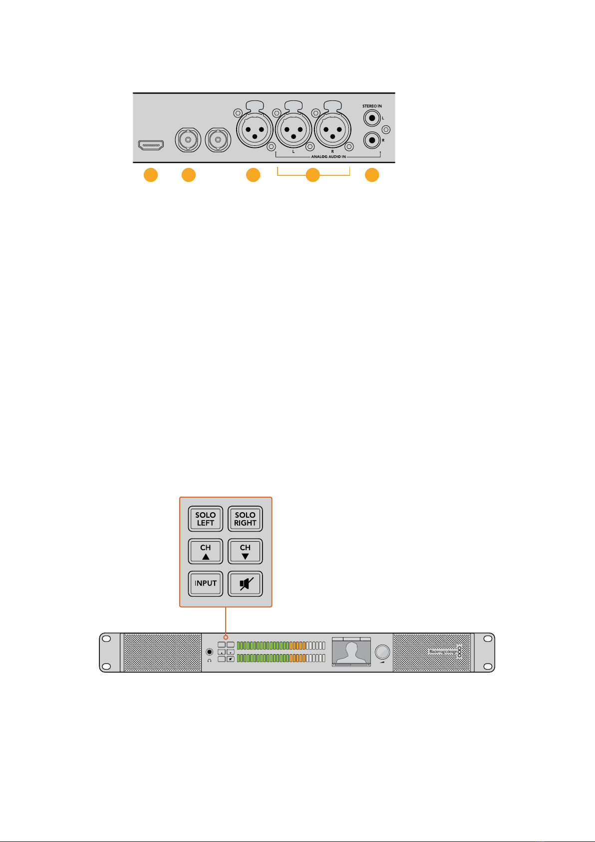
1. HDMI 2. SDI embedded audio 3. XLR for AES/EBU
4. XLR for Analog audio 5. RCA for consumer audio connections
Selecting your Audio Source
After plugging in your audio equipment to Blackmagic Audio Monitor, all you need to do is
select your connection by pressing the INPUT button on the control panel. When your input is
selected and audio is present, you’ll notice the audio level meter LEDs illuminated. The audio
level meter consists of 2 rows of colored LEDs and are brightly lit so you can easily confirm your
audio input is working.
The INPUT button lets you cycle through your audio connections and you can see them on the
color LCD with information including input type, audio channels and volume level. That’s all you
need to do to monitor audio with Blackmagic Audio Monitor.
Connecting Video Outputs
If you need video as well as audio monitoring, Blackmagic Audio Monitor’s video outputs let
you monitor video with audio on a large screen, or connect to more video equipment.
The HDMI output and SDI loop output can be used to monitor video and embedded audio.
You can connect to SD, HD, 2K and even Ultra HD capture devices such as DeckLink 4K
Extreme with a single SDI cable. Connect video with embedded audio to recording decks such
as HyperDeck Studio via SD/HD-SDI or the latest Ultra HD display and projectors via HDMI.
The selection buttons allow you to choose which input you wish to monitor, isolate left and right stereo
channels, move up or down through available audio channels, and mute the speakers or headphones.
PUSH PUSH PUSH
HDMI OUT
USB 2.0
SDI IN SDI LOOP OUT AES/EBU IN
321 54
-45 -30 -20 -10 -3 +3
L
R
0
SOLO
LEFT
SOLO
RIGHT
CH CH
INPUT
SDI 1080PsF/30 Ch1& 2
5Getting Started
Using Blackmagic Audio Monitor
Using the Control Panel
Blackmagic Audio Monitor’s control panel provides fast access to critical functions and status.
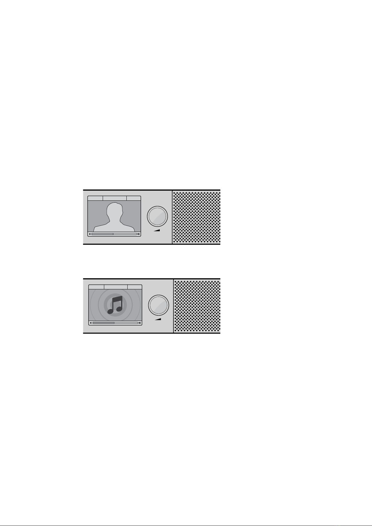
LCD
The built in color LCD features a text overlay that displays important status information, such as
your selected input, the video format if SDI is connected, selected audio channels, and the
volume level for your speakers or headphones. The LCD will also display any incoming SDI
video signal. If there is no SDI video detected, a music icon will be displayed.
The following information is displayed for each selected input:
SDI input
SDI, video format, selected audio channels.
-45 -30 -20 -10 -3 +3
L
R
0
SOLO
LEFT
SOLO
RIGHT
CH CH
INPUT
SDI 1080PsF/30 Ch 1&2
The color LCD displays audio and video information
including connection type, video format, selected
audio channels and volume level.
-45 -30 -20 -10 -3 +3
L
R
0
SOLO
LEFT
SOLO
RIGHT
CH CH
INPUT
Analog Ch 1&2
A music icon is displayed on the LCD unless
monitoring an SDI video signal.
Balanced AES/EBU XLR input
AES/EBU, selected audio channels.
Balanced XLR analog inputs
Analog, selected audio channels.
Unbalanced RCA analog inputs
HiFi, selected audio channels.
6Using Blackmagic Audio Monitor
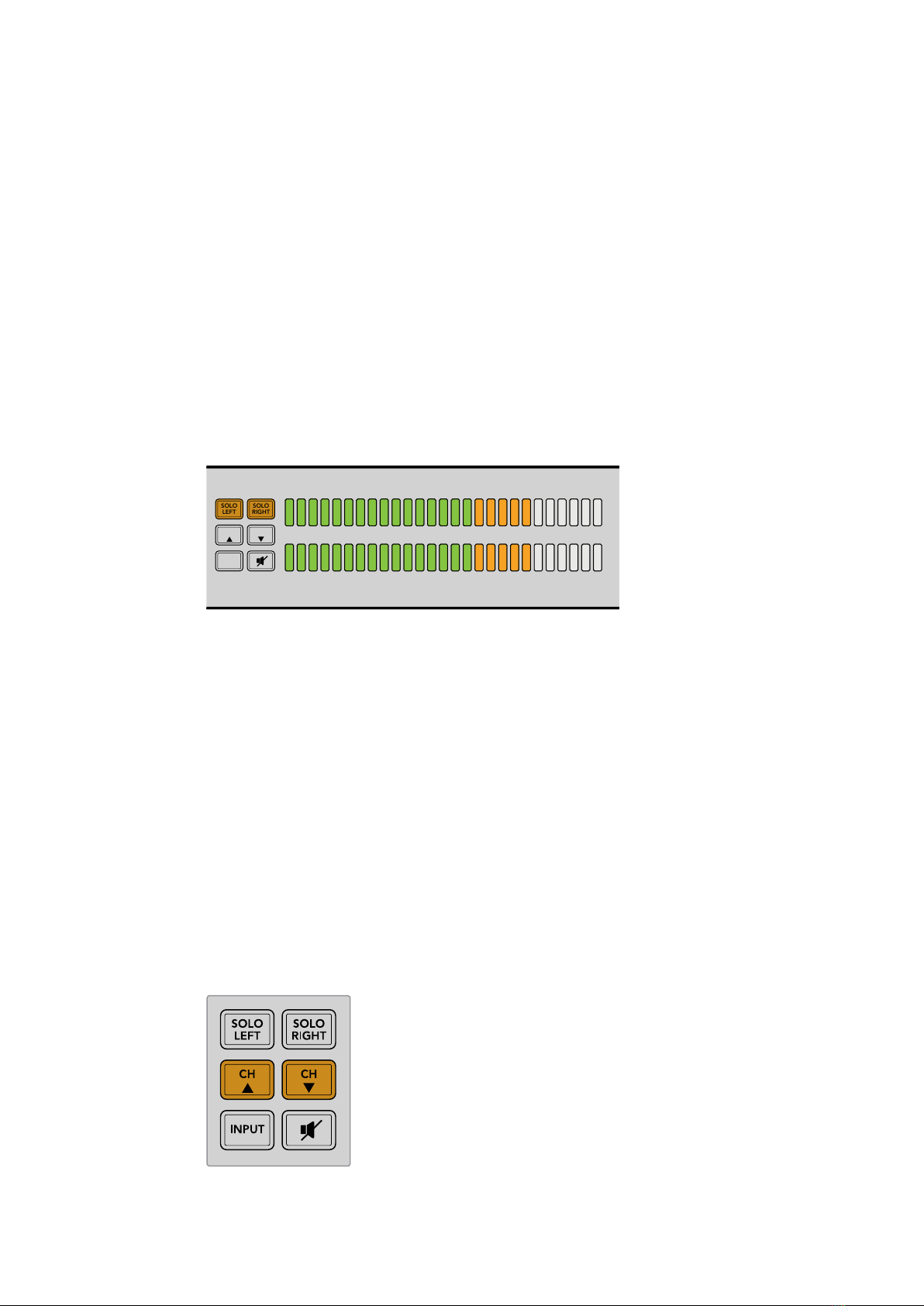
Audio Level Meters
Blackmagic Audio Monitor’s level meters feature two banks of green, orange and red LEDs that
show the strength of your audio levels. If all LEDs are lit, your audio levels are too high and
are clipping.
The behaviour of the audio level meters will change depending on which meter type setting
you have selected in the Audio Monitor Setup utility. If you are using VU metering, adjust the
output levels on your audio equipment so the meter peaks at the 0dB indicator on the control
panel. This maximizes the signal to noise ratio and ensures your audio is at the highest quality.
Ifyour audio peaks beyond the 0dB indicator there is a high risk of sound distortion.
Please refer to the ‘Audio Monitor Setup’ section for information on installing Blackmagic Audio
Monitor Setup and setting the level meter types.
Solo Left and Solo Right
These buttons let you isolate left and right channel audio so you can listen for any potential
audio problems in each channel independently.
-45 -30 -20 -10 -3 +3
L
R
0
SOLO
LEFT
SOLO
RIGHT
CH CH
INPUT
SDI 1080PsF/30 Ch 1&2
Selecting Solo Left deactivates the right audio channel. The audio
level meter will continue to display both levels.
To monitor left channel audio:
1 Press the Solo Left button. The button will become backlit green and your audio
will play through the left speaker only.
2 Press Solo Left again to return to stereo audio monitoring.
To monitor right channel audio:
1 Press the Solo Right button. The button will become backlit green and your audio
will play through the right speaker only.
2 Press Solo Right again to return to stereo audio monitoring.
Channel Up and Channel Down
These buttons let you cycle through 16 channels of audio embedded in your SDI connection.
Press the channel up button to move up through 8 pairs of audio channels. Press the channel
down button to move down through the pairs of channels.
7Using Blackmagic Audio Monitor
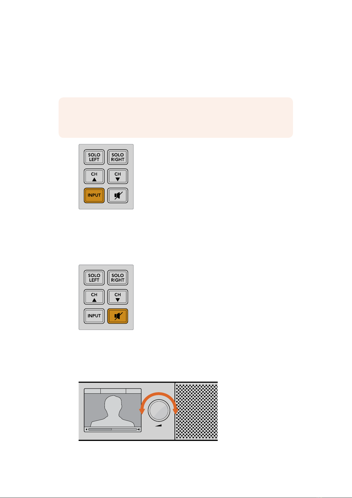
Input
Repeatedly pressing the INPUT button cycles through the SDI, AES/EBU, Analog and HiFi
inputs so you can select which video and audio equipment you wish to monitor.
The selected audio input can be listened to via the built in speakers, plus you can monitor the
audio on CH 1 & 2 of the HDMI output.
NOTE The HDMI output will display black video when the analog, AES/EBU or HiFi
inputs are selected. The SDI Loop output always outputs the video and audio
connected to the SDI input.
Mute
This button mutes Blackmagic Audio Monitor’s control panel speakers and headphones. Muting
the audio will not affect your audio input and will only affect the speakers and headphones
output. Pressing the MUTE button again will restore audio to the control panel speakers or
headphones. Alternatively, increasing the volume will also restore audio.
Volume
This knob adjusts the volume for the speakers or headphones independently. Volume level is
displayed on the built in LCD. When headphones are connected, Blackmagic Audio Monitor’s
speakers will mute and audio is outputted via headphones. Volume can easily be adjusted up
or down by turning the volume knob clockwise or counterclockwise.
-45 -30 -20 -10 -3 +3
L
R
0
SOLO
LEFT
SOLO
RIGHT
CH CH
INPUT
SDI 1080PsF/30 Ch 1&2
The volume level is displayed on the control panel LCD.
8Using Blackmagic Audio Monitor

Audio Monitor Setup
Blackmagic Audio Monitor Setup
The Blackmagic Audio Monitor Setup utility is used toset your desired audio level meter type,
plus update the internal software on your BlackmagicAudio Monitor.
The setup utility can be installed using the included SD card, but we recommend
downloadingthe latest version from the Blackmagic Design support center at
www.blackmagicdesign.com/support.
When the original Blackmagic Audio Monitor is connected to a computer via USB, you can
change the configure settings and update the internal software using the setup utility. On
Blackmagic Audio Monitor 12G, you can also update the unit and change settings via Ethernet,
however, to change network settings you will need to be connected via USB.
Blackmagic Audio Monitor Setup runs on macOS Sierra or later, and Windows 8 or later.
Mac OS X Installation
1 Double click the installer file from the supplied media or from your downloads folder
ifyou downloaded the software from the Blackmagic Design website.
2 Follow the install prompts and Mac OS X will automatically install the software.
Windows Installation
1 Double click the installer file from the supplied media, or downloads folder if you
downloaded the software from the Blackmagic Design website.
2 Follow the install prompts and accept the terms in the License Agreement and
Windows will automatically install the software.
Updating the Internal Software
1 Connect your Blackmagic Audio Monitor to your computer via USB or Ethernet.
2 Open Blackmagic Audio Monitor Setup.
3 Click the configuration icon and the utility will inform you if an update is required.
4 If an update is required, click the ‘update’ button and allow the software installation
to complete.
Click the Update button to apply the internal software update.
A progress bar will show you the status of your update.
9Audio Monitor Setup

5 Click the ‘close’ button when the update is finished.
Update your Blackmagic Audio Monitor’s internal software and change
configuration settings using the Blackmagic Audio Monitor Setup utility
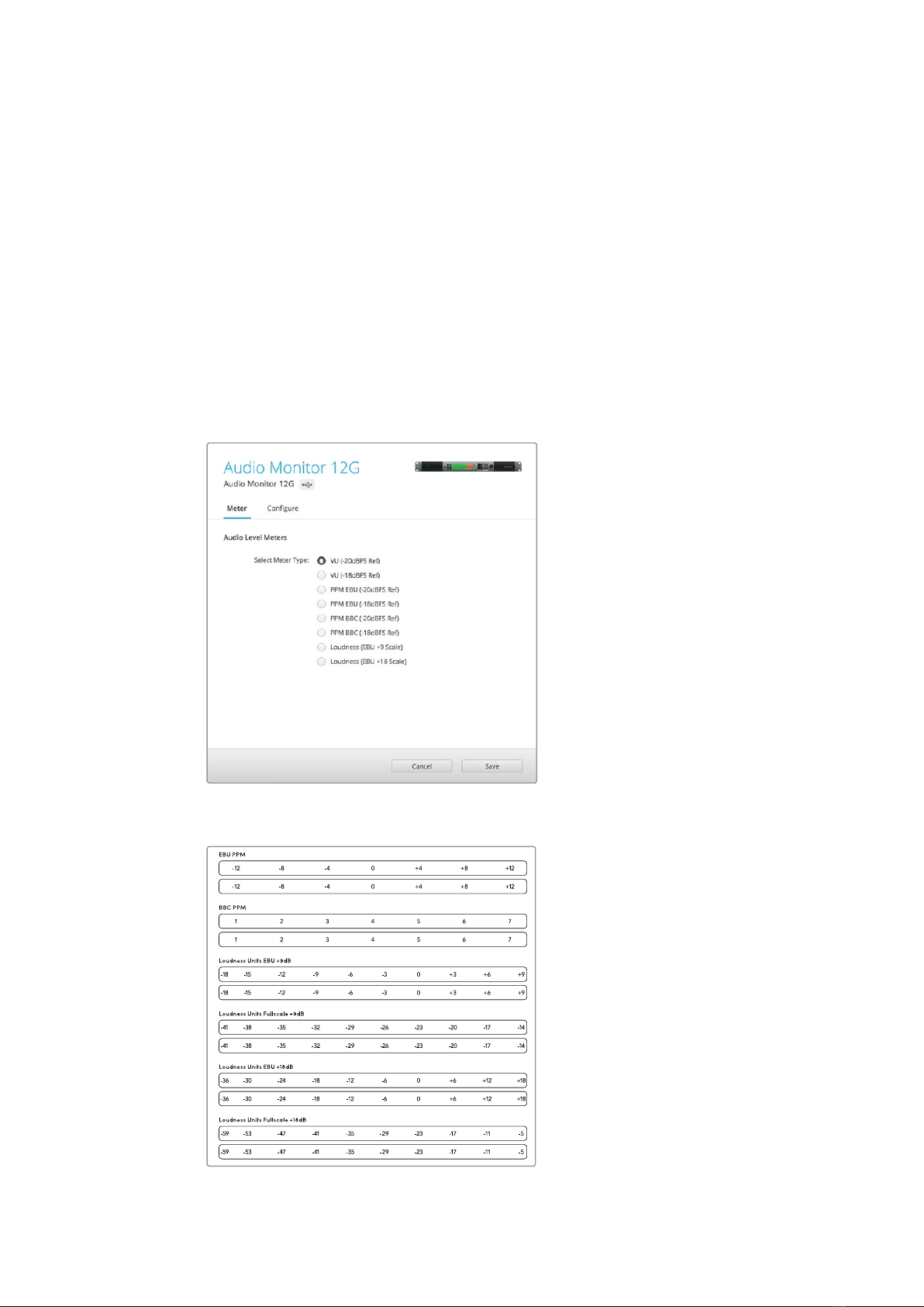
Meter Tab
With the setup utility open, click on the configuration icon to reveal the audio level meters
settings. You can select from VU, PPM or loudness meter types with EBU and BBC
measurement scales. While the VU meter has now become standardized, PPM and loudness
meters provide scaling systems and measurements for perceived loudness. The table on the
following page shows the supported audio level meters and measurement scale combinations.
Meter Type Scale Type Measurement Scale How to Use
VU – -45 to +3 Printed on unit
PPM EBU -12 to +12 Stick-on label
PPM BBC 1 to 7 Stick-on label
Loudness EBU +9 -18 to +9 Stick-on label
Loudness EBU +18 -36 to +18 Stick-on label
Loudness Full Scale +9 -41 to -14 Stick-on label
Loudness Full Scale +18 -59 to -5 Stick-on label
VU
This meter averages out short peaks and troughs in your audio signal. It’s mostly used to
monitor peaks in a signal, however, because of its averaging capability it can also be used to
monitor the perceived loudness of your audio.
PPM
This meter displays a “peak hold” feature that momentarily holds the signal peaks, and a slow
fall back so you can easily see where your audio is peaking.
10Audio Monitor Setup
Loudness
This meter displays the subjective quality of loudness in your audio signal. Today’s broadcast
standards include loudness metering for consistent audio loudness levels.
The VU and PPM meters feature a selectable reference level of -18dB or -20dB so you can
monitor your audio to suit different international broadcasting standards.
Your Blackmagic Audio Monitor’s LED reference behavior will change with each selected meter
type. Stick-on labels with accurate dB reference scales are provided with your
BlackmagicAudio Monitor to help you easily identify where your audio is peaking. To apply the
stick on labels, simply peel and stick the desired scale in between the colored LED meters and
over the current VU scale markings.
Two labels are provided for each audio level meter type and measurement scale. Label sheets
are also available from your local Blackmagic Design support office. Visit the
Blackmagic Design support center at www.blackmagicdesign.com/support to find your local
support team.
To choose a meter setting to display on your Blackmagic Audio Monitor,
click on your desired meter type and then click ‘save’.
Stick-on labels are provided so you can accurately identify
where your audio is peaking for each meter type.
11Audio Monitor Setup

Configure Tab
Blackmagic Audio Monitor 12G has an additional ‘configure’ tab that lists the software version
number and contains your Blackmagic Audio Monitor’s network settings. You can also label
your unit with a custom name. Naming the unit helps you quickly locate it when
connected remotely.
Naming your Blackmagic Audio Monitor 12G
To name your Blackmagic Audio Monitor 12G:
1 Click on the ‘configure’ tab.
2 In the ‘details’ setting, click the ‘name’ text box and enter a new label.
3 Click ‘save’.
Changing Network Settings
Accessing your Blackmagic Audio Monitor 12G over a network is the easiest way to manage
multiple units. You can do this using Blackmagic Audio Monitor Setup. By default, your
Blackmagic Audio Monitor 12G is configured to automatically acquire a network address,
making it easy to immediately select it from the setup utility home screen.
If you are having trouble finding a Blackmagic Audio Monitor 12G on your network, or you have
previously set it to use a static address incompatible with your current network, you may need
to change its network settings locally. You can do this via USB.
Changing Network Settings via USB
To change network settings via USB, connect your Blackmagic Audio Monitor 12G to a
computer running the Blackmagic Audio Monitor Setup utility with a USB cable. You can find
your Blackmagic Audio Monitor 12G’s USB connector on its rear panel. Once connected, select
your Audio Monitor 12G from the Blackmagic Audio Monitor Setup utility home screen, and
navigate to the ‘configure’ tab. Here you can toggle between dynamic and static network
addresses. If you select a static IP, you can manually configure the address, subnet mask,
and gateway.
12Changing Network Settings

Installing the optional
BlackmagicDolby®Decoder Module
Dolby has now discontinued the Dolby decoder module, however if you have the module for
the original Blackmagic Audio Monitor and would like to install it, please follow the instructions
on this page.
NOTE Blackmagic Audio Monitor 12G does not support the optional
Dolbydecodermodule.
WARNING
Ensure that power is disconnected from your Blackmagic Audio Monitor before
installing the Dolby decoder module, as installation requires the removal of the chassis
lid to access the motherboard. This process should only be performed byqualified
individuals. Precautions should also be taken to reduce the risk of electrostatic
discharge while installing the module.
Installing the Module
By installing a Blackmagic Dolby decoder module you can monitor Dolby Digital or Dolby E
audio used in modern film and television productions. Dolby 5.1 surround sound is encoded
with front left and right channels, rear surround left and right channels, a center channel, plus
one channel for low bass frequencies.
The Dolby decoder is a 72 pin SIMM module that is easily installed into the empty SIMM slot on
Blackmagic Audio Monitor’s motherboard.
To install the Blackmagic Dolby decoder module:
1 Ensure Blackmagic Audio Monitor’s power is unplugged.
2 Unscrew all Blackmagic Audio Monitor’s 21 lid screws using a Phillips head screwdriver.
Remove the lid.
3 Hold the Blackmagic Dolby decoder module with its contacts facing the empty SIMM
slot. The SIMM’s keyway needs to be aligned with the slot key or the SIMM will not seat.
4 Gently insert the module into the SIMM slot until the contacts are firmly seated.
5 Lean the module towards the rear of Blackmagic Audio Monitor until the metal clips
fasten to each side of the module.
6 Replace Blackmagic Audio Monitor’s lid and screw in the 21 lid screws.
After installing the Blackmagic Dolby decoder module, place the supplied Dolby sticker
on Blackmagic Audio Monitor’s back panel near the warning label so you can easily see
the Dolby module has been installed.
13Installing the optional BlackmagicDolby® Decoder Module

Confirming Dolby Audio
When Dolby encoded audio is detected by Blackmagic Audio Monitor the Dolby logo will
appear on the top right corner of the control panel LCD. You can monitor 4 pairs of Dolby
surround channels by pressing the control panel channel up and down buttons.
A
Holding the Blackmagic Dolby
decoder module by the top edges,
align the module’s keyway to the
SIMM slot key and gently insert the
module until it is firmly seated.
B
Lean the Blackmagic Dolby
decoder module towards the
rear of the chassis until the
metal clips fasten to both sides
14Installing the optional BlackmagicDolby® Decoder Module

Developer Information
Controlling Blackmagic Audio Monitor 12G using Telnet
The Blackmagic Audio Monitor 12G Ethernet Protocol gives you the freedom to build your own
custom control solutions for your Blackmagic Audio Monitor 12G. For example, you can create
your own software application or web interface to control your Blackmagic Audio Monitor 12G
via Ethernet from your computer.
The first step is to connect your Blackmagic Audio Monitor 12G to your computer via Ethernet.
You can do this by connecting to the same network your computer is connected to, or you can
connect Blackmagic Audio Monitor 12G directly to your computer.
NOTE If Blackmagic Audio Monitor 12G is connected directly to your computer, set
your computer to a manual static IP address. Set the first three blocks of numbers in the
IP address to match your Blackmagic Audio Monitor 12G and set the subnet mask to
255.255.255.0. You can leave the gateway or router setting blank as it will not be used
in a direct connection between your computer and Blackmagic Audio Monitor 12G.
If your network settings are set correctly, you can now open the Terminal application on macOS,
or enable Telnet command line utilities on Windows and enter Blackmagic Audio Monitor 12G
Ethernet Protocol commands. These commands can be programmed into your application and
triggered by related items on a custom user interface of your own design.
Using Telnet on macOS and Windows
1 On macOS, open the Terminal application which is located within the Applications >
Utilities folder.
To open the command prompt in Windows, click on the ‘start’ menu and type ‘cmd’ in
the search bar. Press ‘enter’.
2 Type in “telnet” and a space followed by the IP address of your computer, then another
space and “9996”, which is the default port number for Blackmagic Audio Monitor 12G.
For example:
telnet 192.168.25.253 9996
Press ‘enter’. The Protocol Preamble screen will appear.
Blackmagic Audio Monitor 12G Ethernet Protocol V1.0
Summary
The Blackmagic Audio Monitor 12G Ethernet Protocol is a text based protocol that is accessed
by connecting to TCP port 9996 on a Blackmagic Audio Monitor 12G.
The Blackmagic Audio Monitor 12G sends information in blocks which each have an identifying
header in all-caps, followed by a full-colon. A block spans multiple lines and is terminated by a
blank line.
Each line in the protocol is terminated by a new line character.
15Developer Information

Upon connection, the Blackmagic Audio Monitor 12G sends a complete dump of the state of the
device. After the initial status dump, status updates are sent every time the Blackmagic Audio
Monitor 12G status changes.
To be resilient to future protocol changes, clients should ignore blocks they do not
recognize,up to the trailing blank line. Within existing blocks, clients should ignore lines they do
notrecognize.
Legend
↵line feed or carriage return
… and so on
Version 1.0 of the Blackmagic Audio Monitor 12G Ethernet Protocol was released with
Blackmagic Audio Monitor 12G 3.0 software.
Protocol Preamble
The first block sent by the Blackmagic Audio Monitor 12G is always the protocol preamble:
PROTOCOL PREAMBLE:
Ve r si o n: 1.0
The version field indicates the protocol version. When the protocol is changed in a compatible
way, the minor version number will be updated. If incompatible changes are made, the major
version number will be updated.
Device Information
The next block contains general information about the connected Blackmagic Audio Monitor
12G device. If a device is connected, the Blackmagic Audio Monitor 12G will report the attributes
of the Blackmagic Audio Monitor 12G:
AUDIOMONITOR DEVICE:↵
Model: Blackmagic Audio Monitor 12G
Label: Blackmagic Audio Monitor 12G
Only the label can be modified.
AUDIOMONITOR DEVICE:↵
Label: My new name↵
↵
The response will be
ACK:
AUDIOMONITOR DEVICE:
Label: My new name
The next block will show the network settings which can only be changed via the Blackmagic
Audio Monitor Setup utility when connected over USB. This is for information only.
NETWORK:
Dynamic IP: 1
C u r r e n t a d d r e s s: 0.0.0.0
C u r r e n t s u b n et: 0.0.0.0
C ur re nt g at ew ay: 0.0.0.0
The next block is the meter type.
AUDIO METER:
Meter Mode: VU (-20dBFS Ref)
16Developer Information

This can be changed to VU (-20dBFS Ref), VU (-18dBFS Ref), PPM EBU (-20dBFS Ref),
PPM EBU (-18dBFS Ref), PPM BBC (-20dBFS Ref), PPM BBC (-18dBFS Ref), Loudness (EBU +9
scale) or Loudness (EBU +18 scale)
AUDIO METER:↵
Meter Mode: Loudness (EBU +18 scale)
↵
↵
The response will be
ACK:
AUDIO METER:
Meter Mode: Loudness (EBU +18 scale)
The next block is the input type.
AUDIO INPUT:
Routing: Speaker Stereo SDI Stereo 1-2
This can be changed to SDI Stereo 3-4, SDI Stereo 5-6, SDI Stereo 7-8, SDI Stereo 9-10, SDI
Stereo 11-12, SDI Stereo 13-14, SDI Stereo 15-16, XLR AES/EBU Stereo 1-2, XLR Analog Stereo or
RCA Stereo
AUDIO INPUT:↵
Routing: Speaker Stereo XLR AES/EBU Stereo 1-2↵
↵
The response will be
ACK:
AUDIO INPUT:
Routing: Speaker Stereo XLR AES/EBU Stereo 1-2
The next block is the audio output state. This indicates the current headphone and speaker
volume settings as well as the state of the mute and solo buttons.
AUDIO OUTPUT:
Gain: Speaker Stereo 0
Gain: Headphone Stereo 0
Mut e: false
Solo: Off
The volume gain settings can be set between 0 and 255. Mute can be true or false and Solo
can be Off, Left or Right
AUDIO OUTPUT:↵
Gain: Speaker Stereo 125↵
Solo: R ig ht↵
↵
The response will be
ACK:
AUDIO OUTPUT:
Gain: Speaker Stereo 125
Solo: R ig ht
17Developer Information

Checking the Connection
While the connection to the Blackmagic Audio Monitor 12G is established, a client may send
aspecial no-operation command to check that the Blackmagic Audio Monitor 12G is
stillresponding:
PING:↵
↵
If the Blackmagic Audio Monitor 12G is responding, it will respond with an ACK message as for
any other recognized command.
Checking valid Protocol Commands
While the connection to the Blackmagic Audio Monitor 12G is established, a client may send a
special HELP command to obtain a list of supported Telnet commands:
HELP:↵
↵
AUDIOMONITOR DEVICE:
Model: <label> [read only]
Label: <label>
Unique ID: <label> [read only]
NETWORK:
Dynamic IP: <boolean> [read only]
Current address: <IP _ address> [read only]
Current subnet: <IP _ address> [read only]
Current gateway: <IP _ address> [read only]
AUDIO METER:
Meter Mode: <enum> -> <enum> = <”VU (-20dBFS Ref)” | “VU (-18dBFS
Ref)” | “PPM EBU (-20dBFS Ref)” | “PPM EBU (-18dBFS Ref)” | “PPM BBC
(-20dBFS Ref)” | “PPM BBC (-18dBFS Ref)” | “Loudness (EBU +9 scale)”
| “Loudness (EBU +18 scale)”>;
AUDIO INPUT:
Routing: <enum1> <enum2> -> <enum1> = <”Speaker Stereo”>; <enum2>
= <”SDI Stereo 1-2” | “SDI Stereo 3-4” | “SDI Stereo 5-6” | “SDI
Stereo 7-8” | “SDI Stereo 9-10” | “SDI Stereo 11-12” | “SDI Stereo
13-14” | “SDI Stereo 15-16” | “XLR AES/EBU Stereo 1-2” | “XLR Analog
Stereo” | “RCA Stereo”>;
AUDIO OUTPUT:
Gain: <enum> <integer> -> <enum> = <”Speaker Stereo” | “Headphone
Stereo”>; <integer> = <0..255>;
Mute: <boolean> -> <boolean> = <true | false>;
Solo: <enum> -> <enum> = <”Off” | “Left” | “Right”>;
18Developer Information

Help
Getting Help
The fastest way to obtain help is to go to the Blackmagic Design online support pages and
check the latest support material available for your Blackmagic Audio Monitor.
Blackmagic Design Online Support Pages
The latest manual, software and support notes can be found at the Blackmagic Design support
center at www.blackmagicdesign.com/support.
Blackmagic Design Forum
The Blackmagic Design forum on our website is a helpful resource you can visit for more
information and creative ideas. This can also be a faster way of getting help as there may
already be answers you can find from other experienced users and Blackmagic Design staff
which will keep you moving forward. You can visit the forum at https://forum.blackmagicdesign.com
Contacting Blackmagic Design Support
If you can’t find the help you need in our support material or on the forum, please use the
“Send us an email” button on the support page to email a support request. Alternatively, click
on the “Find your local support team” button on the support page and call your nearest
Blackmagic Design support office.
Checking the Software Version Currently Installed
To check which version of Blackmagic Audio Monitor Setup is installed on your computer, open
the About Blackmagic Audio Monitor Setup window.
On Mac OS, open Blackmagic Audio Monitor Setup from the Applications folder.
Select About Blackmagic Audio Monitor Setup from the application menu to reveal
theversion number.
On Windows 8, open Blackmagic Audio Monitor Setup from the Blackmagic
AudioMonitor Setup tile on your Start page. Click on the Help menu and select
AboutBlackmagic Audio Monitor Setup to reveal the version number.
How to Get the Latest Software Updates
After checking the version of Blackmagic Audio Monitor Setup installed on your computer,
please visit the Blackmagic Design support center at www.blackmagicdesign.com/support to
check for the latest updates. While it is usually a good idea to run the latest updates, it is wise to
avoid updating any software if you are in the middle of an important project.
19Help

Regulatory Notices
Disposal of waste of electrical and electronic equipment within the European union.
The symbol on the product indicates that this equipment must not be disposed of with
other waste materials. In order to dispose of your waste equipment, it must be handed
over to a designated collection point for recycling. The separate collection and
recycling of your waste equipment at the time of disposal will help conserve natural
resources and ensure that it is recycled in a manner that protects human health and the
environment. Formore information about where you can drop off your waste
equipment for recycling, please contact your local city recycling office or the dealer
from whom you purchased the product.
This equipment has been tested and found to comply with the limits for a Class A digital
device, pursuant to Part 15 of the FCC rules. These limits are designed to
providereasonable protection against harmful interference when the equipment is
operated in a commercial environment. This equipment generates, uses, and can
radiate radio frequency energy and, if not installed and used in accordance with the
instructions, maycause harmful interference to radio communications. Operation of this
product in a residential area is likely to cause harmful interference, in which case the
user will be required to correct the interference at personal expense.
Operation is subject to the following two conditions:
1 This device may not cause harmful interference.
2 This device must accept any interference received, including interference that may
cause undesired operation.
Connection to HDMI interfaces must be made with high quality shielded HDMI cables.
This equipment has been tested for compliance with the intended use in a commercial
environment. If the equipment is used in a domestic environment, it may cause radio
interference.
20Regulatory Notices
Other manuals for Teranex Mini IP Video 12G
1
Table of contents


