Blue Flame BFCO-1 User manual
1
INSTALLATION & OPERATION MANUAL
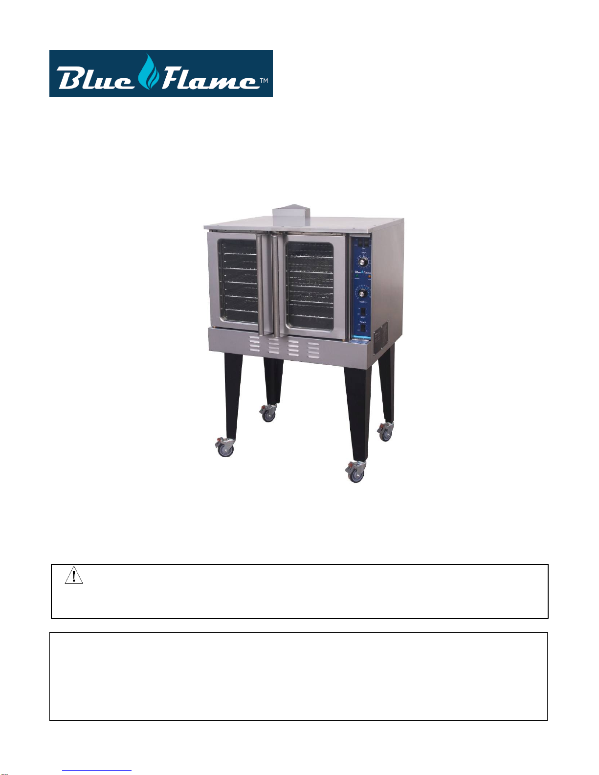
Gas Convection Oven
MODEL:BFCO-1
Blue Flame
223 W. Rosecrans Ave.
Gardena CA 90248 USA
Tel : 1.866.677.8500 / 1.310.808.0102
Fax :1.310.808.0242 /1.310.808.0262
WARNING: IMPROPER INSTALLATION, ADJUSTMENT, ALTERATION, SERVICE OR MAINTENANCE
CAN CAUSE PROPERTY DAMAGE, INJURY OR DEATH. READ THE INSTALLATION, OPERATING AND
MAINTENANCE INSTRUCTIONS THOROUGHLY BEFORE INSTALLING OR SERVICING THIS EQUIPMENT.
DANGER
If you smell gas:
• Shut off gas to the appliance.
• Extinguish any open flame.
• If odor continues, keep away from the appliance and immediately call your gas supplier or your
fire department.
2
death.
NOTICE
! WARNING
! CAUTION
SAFETY
PRECAUTIONS
Beforeinstallingandoperatingthisequipment,besureeveryoneinvolvedinitsoperationisfullytrained
andawareofprecautions.Accidentsandproblemscanbecausedbyfailuretofollowfundamentalrules and precautions.
Thefollowing symbols,foundthroughoutthismanual,alertyouto potentiallydangerousconditionstothe operator,
service personnel, or to the equipment.
!DANGERThissymbolwarnsofimmediatehazardswhichwillresultinsevereinjuryor
Thissymbolreferstoapotentialhazardorunsafepracticewhichcouldresultin injury or death.
Thissymbolreferstoapotentialhazardorunsafepracticewhichcouldresultin injury, product
damage, orproperty damage.
Thissymbolreferstoinformationthatneedsspecialattentionormustbefully understood, even
though not dangerous.
!WARNING
FIRE HAZARD
FOR YOUR SAFETY
Donotstoreorusegasolineorotherflammablevaporsandliquidsinthevicinityofthisoranyother appliance.
Keep area around appliances free and clear of combustibles.
Purchaserofequipmentmustpostinaprominentlocationdetailedinstructionstobefollowedinthe event the
operatorsmells gas. Obtain theinstructionsfrom the local gas supplier.
!WARNING
Electrical GroundingThis appliance is equipped with a three-prong (grounding) plug for your protection
against shockhazard and should be plugged directly into a properly grounded three-prong receptacle.
And Do not cut orremove the grounding prong from the plug.
!WARNING
Asphyxiation canresult from improper ventilation. Do notobstruct the flow of combustion and ventilation air to
and from your cooking equipment.
NOTICE
BesurethisOperator’sManualandimportantpapersaregiventotheproperauthoritytoretainfor futurereference.
NOTICE
This product is intended for commercial use only. NOT FOR HOUSEHOLD USE.
Copyright © 2017 byBLUE FLAME.
All rights reserved.
Published in the United States of America.

3
TABLE OF CONTENTS
Congratulations! You have purchased one of the finest pieces of heavy-duty commercial cooking
equipment.
Youwill findthatyournew equipment,hasbeen designedand manufactured
tomeetthetougheststandardsintheindustry.Each pieceofequipmentiscarefullyengineered
anddesignsareverified throughlaboratorytestsandfieldinstallations.Withproper careandfield
maintenance,youwillexperienceyearsofreliable, trouble-free operation.Forbestresults,read this manual
carefully.
RETAIN THISMANUAL FOR FUTUREREFERENCE.
Table of Contents
Specifications.........................................................................................................................4
Installation..............................................................................................................................8
Operation..............................................................................................................................13
Cooking Hints.......................................................................................................................14
Cleaning...............................................................................................................................17
Adjustments..........................................................................................................................19
Troubleshooting....................................................................................................................22
Parts...................................................................................................................................26
Replacing Oven lamp............................................................................................................30
Natural to LP gas conversion Procedure...................................................................................31
Readtheseinstructionscarefullybeforeattempting installation. Installationandinitialstartupshouldbe
performedby aqualifiedinstaller.Unlesstheinstallationinstructionsforthisproductarefollowedbya
qualifiedservicetechnician (apersonexperiencedinandknowledgeable withtheinstallation ofcommercial gas )
then the terms and conditions on the Manufacturer’s Limited Warranty will be renderedvoid and
nowarranty of any kind shallapply.
Please contact a local service company to perform maintenance and repairs
In the event you have questions concerning the installation, use, care, or serviceof the product, write to:

4
SPECIFICATIONS
NOTICE
Localcodesregardinginstallationvarygreatlyfrom oneareatoanother.TheNationalFire Protection
Association, Inc.statesinitsNFPA 96latesteditionthatlocalcodesarethe“authorityhaving jurisdiction”
whenit comestoinstallationrequirementsfor equipment.Therefore,installations should comply with all
local codes.
Producerreservestherightto changespecificationsandproductdesign withoutnotice.Such revisionsdo
notentitlethebuyertocorrespondingchanges,additions,orreplacementsforpreviously purchased
equipment.
This product is intended for commercial use only, not for householduse.
Theinstallationmustconformwithlocalcodes,orintheabsenceoflocalcodes,withtheNational
FuelGasCode,ANSIZ223.1,Natural GasInstallationCode,CAN/CGA-B149.1,orthePropane
InstallationCode CAN/CGA-B149.2,asapplicable, including:
1. Theapplianceanditsindividualshutoffvalvemustbedisconnectedfromthegassupplypiping
systemduringanypressuretestingofthatsystemattestpressuresinexcessof1/2psi(3.45 kPa).
2. Theappliancemustbeisolatedfrom thegas supplypiping system byclosingitsindividual manual
shutoffvalveduringanypressuretestingofthegassupplypipingsystemattestpressuresequal to or less
than 1/2 psi (3.45 kPa).
ELECTRICITY SUPPLY
Convection ovens require connection toa supplyofelectricity. Theappliance,wheninstalled,mustbe
electricallygroundedinaccordance withlocalcodes,orintheabsenceoflocalcodes,withtheNational Electrical
Code,ANSI/NFPA70, orthe CanadianElectrical Code,CSA C22.2, asapplicable.Anelectrical
diagramislocatedonthe sideofthecontrolpanelassembly(see drawingonpage20).Electricaldiagrams can
also be found in this manual beginning on page21.
Power Option
Power
# of Ovens
Maximum Amps
120/60/1 120Volts,60Hz,SinglePhase Single-Deck 9.3
Single-deckovenswillhaveone120 volt single phase powercord.
GAS SUPPLY
The serial plateindicatesthetype of gasthe unitisequippedto burn. All equipment is adjusted at the factory.
Check type of gas on serial plate.
Thesemodelsaredesign-certified foroperationon naturalorpropanegases.Fornatural gas,theregulator is set to
deliver a 4" W.C. pressure to the manifold.For propanegas, it is set to deliver 10"W.C.
Ifapplicable,theventlinefromthegasappliancepressureregulatorshallbe installedtotheoutdoorsin
accordancewithlocalcodes,orintheabsenceoflocalcodes,withtheNationalFuelGasCode,ANSI
Z223.1,NaturalGasInstallationCode, CAN/CGA-B149.1, orthe PropaneInstallationCodeCAN/CGA-
B149.2,as applicable.
This appliance should beconnected ONLY to the type of gas forwhich it is quipped.
A3/4"NPTlineisprovidedattherearforthegasconnection.Anadequategassupply isimperative. Undersizedorlow
pressurelines willrestrictthevolumeofgasrequiredfor satisfactory performance.
Fluctuationsofmorethan25%onnaturalgasor10%onpropanegaswillcreateproblemsandaffect burner operating
characteristics.

5
Anadequate gas supplylinetotheunit shouldbe nosmallerthantheinsidediameterofthepipefromthe unit to
which it is connected.
Purge thesupply line to clean out dust, dirt, or other foreign matter beforeconnecting the lineto the unit.
Allpipejointsandconnectionsmustbetestedthoroughlyforgasleaks.Useonly soapywaterfortestingon
allgases.NEVERuseanopenflametocheckforgasleaks.Allconnectionsmustbecheckedforleaks after the unit
has been put into operation.Test pressure should notexceed 1/4" W.C.
Model # of Ove
ns
Oven
Depth
Type ofGas Orifice Size
# of Burners Total BTU
Convection oven
Single-
Deck 22.5” Natural Gas 45 3 @ 18,000 BTU
54,000
LP 55
THIS APPLIANCE IS EQUIPPED FOR NATURAL GAS.
All oven shipped for Natural Gas.
Each oven is shipped with an LP Gas Conversion kit,
--Regulation spring (FS Part # 001)
--LP orifices (FS Part # 002)
For conversion to LP gas see the conversion instruction(Page.29).
6

7
MINIMUMCLEARANCES
!WARNING
There must be adequate clearance between the left side of the ovens and combustibleconstruction.
Minimum Clearance from
Combustible
C i
Minimum Clearance from
Non-Combustible
C i
Back
6"
6"
Right Side
6"
0"
Left Side
6"
0"
Adequate clearancemustbeprovidedintheaisletoallowthedoorstoopensufficientlytopermitthe removal of
the racks and for serviceability.
Althoughno clearanceisrequiredbehindthemotorontherear oftheoven,caremustbe takento provide
adequate air circulation to prevent the motor from overheating.
Donotlocate theovenadjacenttoanyhighheator grease-producingpieceofequipment,suchasa
rangetop,griddle,fryer,etc.,thatcouldallowradiantheattoraise theexteriortemperatureof theoven above
130°F(54°C). DO NOT MOUNTABOVE OTHER COOKING EQUIPMENT.
VENTILATION
! WARNING
Improperventilationcan resultinpersonalinjuryordeath.Ventilationwhichfailstoproperly remove flue
products cancause headaches, drowsiness, nausea, orcould result in death.
Allunits mustbeinstalled in such amannerthat theflowof combustionandventilation airare not
obstructed.Provisionsfor adequateair supplymust beprovided.Donotobstructthefrontorrear of the unit as
combustion airenters through these areas.
Besureto inspectand cleanthe ventilationsystemaccordingtothe ventilationequipment manufacturer’s
instructions.
NOTICE
Properventilationistheowner’sresponsibility.Anyproblemduetoimproperventilationwillnotbe covered by the
warranty.
Ifaventilationcanopyisused,itisrecommendedthatacanopy extend6"pasttheapplianceandthatthe
bottomedge belocated6'6"fromthefloor.Filtersshould beinstalledatanangleof45°ormorefromthe horizontal.
Thispositionprevents drippinggreaseandfacilitatescollectingtherun-off greaseinadrippan, unusually
installed with a filter.
Ifanexhaust fanisused,itshouldbeinstalledatleast2"abovetheflueopeningatthetopoftheunit.A
strongexhaustfantendstocreateavacuumintheroomandmay interferewithburnerperformance.Fresh
airopeningsapproximatelyequaltothefanareawillrelievesuchavacuum. Incaseofunsatisfactory performance
onanyappliance,checktheappliance withtheexhaustfaninthe “OFF”position.Dothisonly longenough
tocheckequipmentperformance.Then turnthe exhaustfan backonandletitrunto remove any exhaust that
may have accumulatedduring the test.
Iftheovenflueisconnecteddirectly toanoutside flue,aCSAInternational designcertifieddowndraft diverter
mustbe installed atthe flue outlet of the oven and connected to the outside flue.

8
INSTALLATION
NOTICE
These installation procedures must be followed by qualified personnel or warranty will be void.
Localcodesregardinginstallationvarygreatlyfrom oneareatoanother.TheNationalFire Protection
Association, Inc.statesinitsNFPA 96latesteditionthatlocalcodesarethe“authorityhaving jurisdiction” whenit
comestoinstallationrequirementsfor equipment.Therefore,installations should comply with all local codes.
Theinstallationmustconformwithlocalcodes,orintheabsenceoflocalcodes,withtheNational
FuelGasCode,ANSIZ223.1,Natural GasInstallationCode,CAN/CGA-B149.1,orthePropane
InstallationCode CAN/CGA-B149.2,asapplicable, including:
1. Theapplianceanditsindividualshutoffvalvemustbedisconnectedfromthegassupplypiping
systemduringanypressuretestingofthatsystemattestpressuresinexcessof1/2psi(3.45 kPa).
2. Theappliancemustbeisolatedfrom thegas supplypiping system byclosingitsindividual manual
shutoffvalveduringanypressuretestingofthegassupplypipingsystemattestpressuresequal to or less
than 1/2 psi (3.45 kPa).
Step 1: Unpacking
IMMEDIATELY INSPECT FOR SHIPPING DAMAGE
Allcontainersshould be examined for damage before and during unloading.Thefreight carrierhas
assumedresponsibilityforitssafe transitand delivery.Ifdamagedequipmentisreceived,either apparent or
concealed, a claim must bemade with the delivering carrier.
Apparentdamageorloss mustbenotedonthefreightbillatthetimeofdelivery.Thefreight billmust
thenbesignedbythecarrierrepresentative(Driver).Ifthebillisnotsigned,thecarriermayrefuse the claim. The
carrier can supply the necessary forms.
Arequestforinspectionmustbe made tothecarrier within15daysifthereisconcealeddamage or lossthatis
notapparentuntilaftertheequipment isuncrated. Thecarriershouldarrangean inspection. Be certain to hold all
contents plus all packing material.
1. Cut bandingstraps and remove packing material.
2. Cut bandingstrap holding oven to wooden skid.
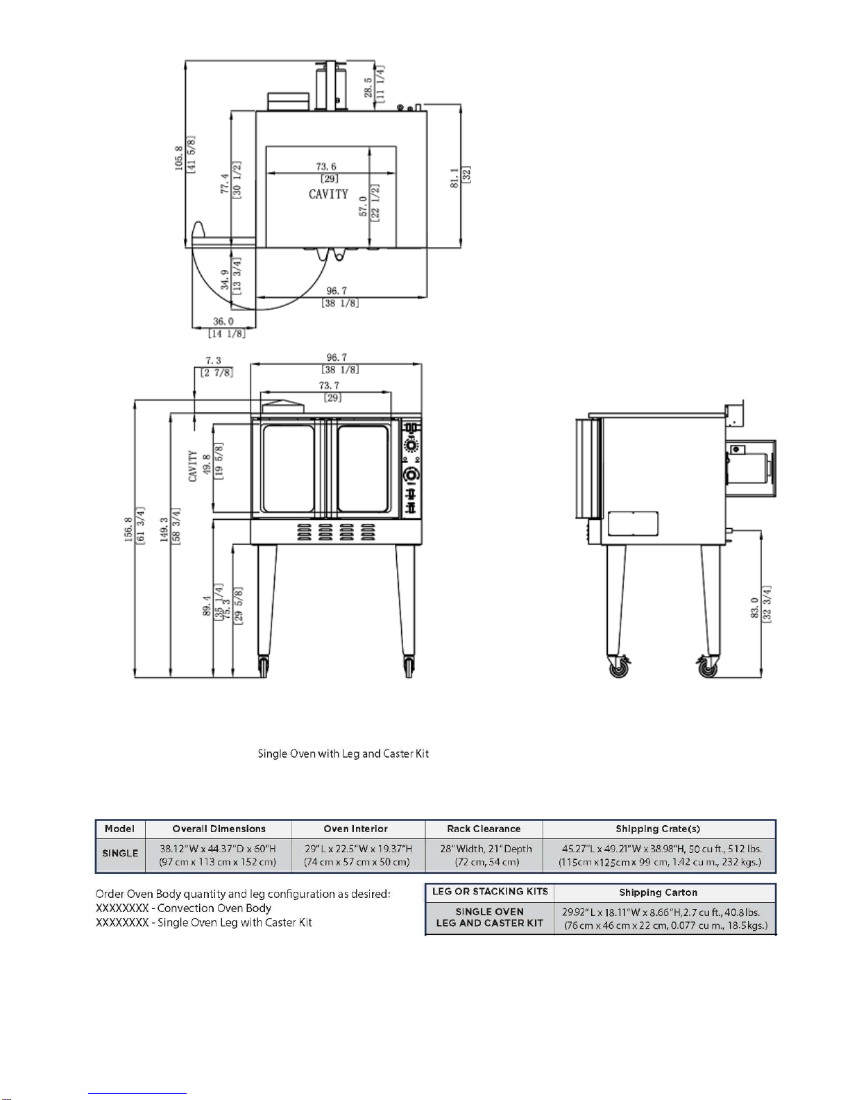
Step 2: Installation ofLegs on Single-Deck Ovens (For Stacking kit, refer to instructions
included with kit)
1. Raiseovensufficientlytoallowclearanceforthelegstobeattached.Use ofalifttruckorother mechanicalliftingmeans
isrecommended.For safety,“shoreup”and supporttheoven withan adequateblockingarrangementstrong
enoughtosupporttheload.(Ifitisabsolutelynecessarytorest theovenonitsside,restit onitsleftside.)
2. Attachthelegstothebottomcornersoftheoven usingtheprovidedmachinescrewsand lock washers. Each leg
issecured by 3 screws. The mounting holes are pre-drilled and threaded.
3. Lower the oven gently onto a level surface. Never drop or allow the oven to fall.
4. Makesurethattheovenislevel.
5. Install required cable restraint connecting oven to wall.

9
Step 3: Installation of Restraint (Only for Ovens with Casters)
NOTICE
When this appliance is installed with casters, it must be installed with the caster supplied, a
connector complying with either ANSI Z21.69 or CAN/CGA-6.16 and a quick-disconnect
device complying with either ANSI Z21.41 or CAN1-6.9. It must be installed with a restraining
means to guard against transmission of strain to the connector, as specified in the appliance
manufacturer’s installation instructions.
!WARNING
To avoid accidental gas disconnection and potential explosion:
Ifdisconnectionofthisrestraintisnecessarytomovetheapplianceforcleaning,etc.,reconnectit when the
appliance is moved to its originally installedposition.

10
Step 4: Connect Electricity
!WARNING
ELECTRIC GROUNDING INSTRUCTIONS
Thisappliance(120Vovensonly)isequipped withathree-prong(grounding)plugforyourprotection against shock
hazard and should be plugged directly into a properly grounded three-prong receptacle. Do not cut or
remove the grounding prong from this plug.
NOTICE
Thisappliance,wheninstalled,mustbe electrically groundedinaccordance withlocal codes,orinthe
absence of local codes, with the National Electrical Code, ANSI/NFPA 70or the Canadian Electrical
Code, CSA C22.2, as applicable.
Wiringdiagramsarelocatedonthesideofthecontrol panelassembly,aswellasinthismanual(beginning onpage 21).
Besurethat theinputvoltageandphasematchthe requirementsshownontheserial plate, which is located inside
thelower front panel.
Ovensorderedtooperateon120Vpowerhaveathree-wirecord.Single-ovenunitsrequirea15amperesupply.
Step 5: Connect Gas Supply
NOTICE
Theinstallationmustconformwithlocalcodes,orintheabsenceoflocalcodes,withtheNational
FuelGasCode,ANSIZ223.1,Natural GasInstallationCode,CAN/CGA-B149.1,orthePropane InstallationCode
CAN/CGA-B149.2,asapplicable, including:
1. Theapplianceanditsindividualshutoffvalvemustbedisconnectedfromthegassupplypiping
systemduringanypressuretestingofthatsystemattestpressuresinexcessof1/2psi(3.45 kPa).
2. Theappliancemustbeisolatedfrom thegas supplypiping system byclosingitsindividual manual
shutoffvalveduringanypressuretestingofthegassupplypipingsystemattestpressuresequal to or less than
1/2 psi (3.45 kPa).
A 3/4" NPT line is provided atthe rear for the gas connection.
Ifthisequipmentisbeinginstalledatover2,000feetaltitudeandthatinformationwasnotspecified when ordered,
contact the appropriate authorized Service Representative or the Service
Department.Failuretoinstallwithproperorificesizingwillresult inpoorperformanceandmayvoidthe warranty.
The serial plateislocatedinsidethefrontlowerpanel.Itindicatesthetypeofgastheunit is equipped to burn. All
equipment is adjusted at the factory. Check type of gas on serial plate.
Thesemodelsaredesign-certified foroperationon naturalorpropanegases.Fornatural gas,theregulator is set to
deliver a 3.5" W.C. pressure to the manifold.For propanegas, it is set to deliver 11"W.C.
ThisapplianceshouldbeconnectedONLYtothetypeofgasforwhichitisequipped.The inletpressure before
theregulatorshould be 6-10" W.C. for natural gas or 11-14"W.C. for LP gas.

11
Anadequategassupplyisimperative.Undersized orlowpressurelineswillrestrictthevolumeofgas
requiredforsatisfactoryperformance.Fluctuationsofmorethan25%onnaturalgasor10%onpropane gaswill create
problems and affect burner operating characteristics.
AnadequategassupplylinetotheunitshouldbenosmallerthantheI.D.ofthepipefromtheunittowhich it is connected.
Purge thesupply line to clean out dust, dirt, or other foreign matterbeforeconnecting the lineto the unit.
! CAUTION
ALLPIPEJOINTSANDCONNECTIONSMUSTBETESTEDTHOROUGHLYFORGASLEAKS. USEONLY
SOAPYWATERFORTESTINGONALLGASES. NEVER USEANOPENFLAMETO
CHECKFORGASLEAKS.ALL CONNECTIONS MUSTBE CHECKEDFORLEAKSAFTERTHE UNITHAS
BEEN PUT INTO OPERATION. TEST PRESSURESHOULDNOTEXCEED1/4"W.C.
Step 6: Check the Installation
1. Check that all screws and bolts are tightened.
2. Move the oven into the position at which it will be operated.
3. Check that the oven is level. If not, adjust the legs.
4. Check that the appropriateclearances are satisfied (see page 7)

12
Control Panel
FanSpeed
Use to select fan speed (HI or
LOW).The appropriate speed is
determined bythe type of food
being cooked.
Cook Timer
Turn knob to set a time duration.
An alarmwill soundwhen the timer
runs out. The timer is a reminder
to the user; the timer does not
control theoven
Power on Light
Power Switch
Switch ON to use the oven, switch
OFFwhen done using the oven.
FanMode
In COOK mode, the fan runs
continuouslyexceptwhen thedoors are
open. The fan does NOTcycle with the
operation of the burners. In COOL
mode, the fan runs
continuouslyeven if the doors are
open. Since the burnerswill not
operate if the oven doors areopen, to
rapidlycool the oven after cooking is
completed, open the doors and switch
the fan mode to COOL.
Heat-OnIndicator
Indicator is lit when the burners are
operating.
Cook Temperature Control
Turn knob to select desired cooking
temperature. The Heat On indicator will
go outwhen the oven reaches the set
temperature, andwill cycle on and off
as the burners operate to maintain the
set cooking temperature.
OvenInteriorLightSwitch
On ovens equippedwith an oven
interior light, press to turn on the
light. The light remainson for as
long as the switch is held.

13
OPERATION
!
DANGER EXPLOSION HAZARD
Intheeventagasodorisdetected,shutdownequipmentatthemainshutoffvalve.Immediatelycall the
emergency phone number of your gas supplier.
!CAUTION
Toeliminategasbuildupwhichcouldresultinanexplosion,intheeventofmainburnerignition failure a five minute
purgeperiod must be observed prior to re-establishing ignition source.
NOTICE
Foranapplianceequippedwithaconvectionoven,noattemptshouldbemadetooperateoven during a power
failure.
LIGHTING, RELIGHTING, AND SHUTDOWN INSTRUCTIONS
Tolighttheoven,just switchthepower switch atthe bottom ofthe control paneltothe “ON”position. (The oven
isequipped with a direct hot surface ignition system. There is no pilot to light.)
If the burners fail to ignite within four seconds, the oven will automatically shut offthe gas, wait five
minutes toallowthegasthatwasreleasedtodissipate,andtrytolighttheburnersagain.Iftheburners stillfailto
igniteafterthree suchattempts,theovenwill stoptrying,eventhoughthepowerswitchisinthe “ON” position. To
continue to attempt to light the burners, turn the power switch “OFF” and then “ON” again.
Toshutdown theoven,switchthepowerswitchtothe“OFF”position.
OPERATING THE CONTROLS
Aconvection ovenis adifferenttype ofoventhatoffersmanyfeaturesandadvantagestothe foodservice
operation.Theadditional capabilitiesandfeaturesoftheovenrequiresomelearning. However,the operation
of the oven is notdifficult to understand orcontrol onceyou have some practice.
Operation of STANDARD Models
Models withStandard Controls operatemuch like a standard oven:you turn the oven ON andselect a
cooking temperature. Twoadditional controls are used to control the fan (as described below).
The timer is areminder to you of when to remove foodfrom the oven.The timer does NOT control the
temperature of the oven.
To cook, do the following:
1. Turn the oven ON using the Power Switch at the bottom of the control panel.
2. SelectthedesiredfanspeedusingtheFanSpeedswitch.Theappropriatefanspeed(HIorLOW)depends on
the type of food beingcooked.
3. SwitchtheFanModeswitchtoCOOK. Thefan will run continuouslywhenthe ovendoorsareclosed (thefan
doesnotcycleon andoffwiththeburners).(IfthisswitchissettoCOOLtheonlydifferenceis that the fan will
continue torun when theoven doors are open.)
4. Setthecookingtemperaturebyturning theCookTemperatureControl untiltheindicatormarkonthe
knobispointedtothedesired cookingtemperature.TheHeatOn indicatorwill lightwhentheburners are on,
and will remain on while the oven preheats.

14
5. Waituntilthe HeatOnindicator hascomeonandgoneoutthree times.Atthattimetheovenwillhave reached the set
cooking temperature.
6. Open the oven doors, loadthe product into the oven, and close thedoors.
7. Youcanuse theCookTimerasa reminderofwhentheremovetheloadfromtheoven.Ifsodesired,
turntheCookTimerknob untiltheindicatormarkpointstothedesired cookingtime(upto55 minutes).
Thetimerknobwillrotate counterclockwiseasthetimerrunsdown,indicating howmuchtimeremains. Youcanturn
theknob whilecookingto increase or decreasetheremainingtime.Whenthe timer runs
out,abuzzerwillsoundforashorttime,thenturnitself off.(Toimmediatelysilencethebuzzer,turnthe
CookTimerknobtotheOFFposition.)Thetimerisareminderto you;thetimerdoesnotcontrolthe oven.
Ifyouopentheovendoors,theburnersandfanwillshutoffuntilthedoorsareclosed.However,the timer will continue
running even if the doors are open.
Toturnontheinterior oven lights,use the switch located at the bottom of the control panel.
8. Whentheloadhasfinishedcooking,youcanrapidlycooltheloadbyopeningtheovendoors(which
willshutofftheburners)andswitching theFanModetoCOOL(whichwill causethefantoruneven though the doors
are open). For the most rapid cooling, also switchthe Fan Speed switch toHI.
9.Whenyou are donecooking,turntheCookTemperaturecontroltothelowest setting(fully counterclockwise) and
switch the PowerSwitch to OFF.
COOKINGHINTS
Ina convectionoven,thefan-blown circulatingairstripsawaythisinsulatinglayer allowingthe
heattopenetratefasterforquickerbakingandroasting.Hence,in aconvection oven cooking procedures
andtechniquesmay requiresomemodificationfor successful results.As ageneral rule,the cooking time will be
shorter and the cooking temperature will be 25°F to 75°F lower than those called for in recipes for
astandard oven.
TIME & TEMPERATURE
Timeandtemperature areimportant.The“GuidetoTimesandTemperatures”laterinthissectionisa
startingpoint.Theactualbestcookingtimeandtemperaturewilldependonsuchfactorsassizeofload andmixture
ofrecipe(particularlymoisture).Onceanappropriatetime andtemperaturehasbeen established for a particular
product and load, you willfind the result of succeeding loads to be similar.
OVERLOADING
Do NOToverloadtheoven.The size oftheloadthatcan be cooked satisfactorilydependslargelyon the
particularproduct.Asa rule,fiveracks can be successfullyusedforshallowcakes,cookies, pies,etc.For deeper
cakes(suchasangelfood),useonlythree racksbecauseofthesize ofthepanandthespace requiredforrising.
Forhamburgerpatties,fish sticks,cheese sandwiches,etc.,afull complementof racks and pans is usually
satisfactory.
HELPFULSUGGESTIONS
Herearesomesuggestionsthatwillassistingettingthebestpossibleperformancefromaconvection oven:
•
Pre-heat the oven thoroughly before use.
•
Whenre-thermalizingfrozenproducts,pre-heattheovento50°Fhigherthantheplannedcooking temperature.After
loading,reduce the temperaturesetting to the appropriatecooking temperature.
•
Space theracks and pans as evenly as possible to allow aircirculation.
•
Centertheloadontherackstoallowforproperaircirculationaroundthesides.Donotcovertheracks completely with
pans.
•
Donotuseadeeppanforshallowcakesorcookies,etc.Aircirculationacrossthesurfaceofthe product is essential.

15
!WARNING
THE USEOFALUMINUMFOIL CAN CAUSE HEATDISTRIBUTIONPROBLEMSINOVENS.
EXTREMECAREMUST BEUSEDWHENPLACINGALUMINUMFOILINTHEOVEN TOENSURE THATIT
DOESNOTBLOCKOR CHANGETHE AIRFLOW. THEUSE OFALUMINUMFOILMAY VOID THE
PRODUCTWARRANTY IF ITS USEISASCERTAINEDTOBEAPROBLEM.
HOLDING FOOD BEFORE SERVING
AnyfooditempreparedinsteamtablepanscanbehelduntilbeingservedbysettingtheHoldthermostat to 160°F.
Examples includestuffed porkchops,oysters Rockefeller, and any vegetable entree.
COOKING PROBLEMSAND SOLUTIONS
If…
then…
Cakes are dark on the sides andnot done in the
t
lower oven temperature.
Cake edges are too brown… reduce numberof pans or loweroven temperature.
Cakes have a light outer color… raise temperature.
Cakes settle slightly in the center…
bake longer or raise oven temperature slightly.
Do not open doors except to load or unload
product
Cakes ripple… do not overload pans or use batter that is too thin.
Cakes are too coarse… lower oven temperature.
Pies have uneven color… reduce numberof pies per rack or eliminate useof
bake pans
Brown sugar topping or meringue blows off…
after oven is preheated, turn off oven and put
product in oven until topping sets, then turn oven
back on
Rolls have uneven color… reduce numberor size of pans.
Meats are browned and not done in center… lower oven temperature and roast longer.
Meats are well done and not browned… raise temperature. Limit amount of moisture.
Meats develop hard crust… reduce temperature or place pan of water in oven.
Excessive meatshrinkage occurs… lower oven temperature.
GUIDE TO TIMES AND TEMPERATURES
Asa guide,setoventemperatures25°F to75°Flowerthan called forin recipesfornon-convection ovens, (i.e.,
range ordeck ovens).
Timeandtemperaturewillvarydependinguponload,mix,size,portion,initialtemperatureoffood,and
otherfactors.Usethefollowingchartasastarting pointtodevelopyourown cookingtechniques.Rack loading and
position may affect results. Experimentation may be necessary to suitindividual requirements.
Cooking Time Temperature Number of Racks
Meat and Fish
Top Round, 18-20 lbs. (medium) 5 hours 275°F 1
Prime Ribs (rare) 4 hours 225°F 1
Burger Patties, 4 oz. 10 min. 350°F 5

16
Fish Cakes 10-12 min. 375°F 5
Turkey, 10-12 lbs. 3 hr. 20 min. 225°F 1
Cooking Time Temperature Number of Racks
Baked Goods
Bread, 2 lb. loaf 35 min. 375°F 3
Biscuits 5-10 min. 400°F 5
Cornbread 18 min. 400°F 5
French Bread 10 min. 375°F 5
Sheet Cake 18-20 min. 300°F 5
Cream Puffs 20 min. 375°F 5
Brown & ServeRolls 6 min. 400°F 5
Ginger Bread 18 min. 300°F 5
Yeast Rolls,sheet pan 16-18 min. 325°F 5
Pineapple Upside Down Cake 25-30 min. 325°F 5
Apple Turnovers 15-18 min. 350°F 5
Fruit Cobbler 22-25 min. 375°F 5
Brownies 15 min. 350°F 5
Danish Pastry 12 min. 325°F 5
Pie Shells 12 min. 350°F 5
Fresh Fruit Pies 25-30 min. 350°F 5
Pumpkin Pies 25-30 min. 275°F 5
Fresh Apple Pies 35 min. 375°F 5
Frozen Berry Pies 40 min. 375°F 5
Frozen Fruit Pies 45 min. 375°F 5
Potatoes
Baked Potatoes,10 oz. 50-55 min. 450°F 5
Baked Potatoes,6-8 oz. 40-45 min. 450°F 5
Scalloped Potatoes 35 min. 325°F 5
Miscellaneous
Macaroni and Cheese 30 min. 350°F 5
Stuffed Peppers 18 min. 350°F 5
Toasted Cheese Sandwiches 8 min. 375°F 5

17
CLEANING
Equipmentissturdilyconstructedofthebestmaterialsandisdesignedtoprovidedurable
servicewhentreatedwithordinarycare.Toexpectthebestperformance, yourequipmentmustbe maintainedin good
conditionand cleaneddaily.Naturally,theperiodsforthis careand cleaningdepend on the amount and degree
ofusage.
Following daily and periodic maintenance procedures will enhance long life for your equipment. Climatic
conditions(such as saltair) mayrequiremorethorough and frequent cleaning orthelife of theequipment could be
adversely affected.
Theoveninteriorisfinishedwithaporcelainenamelcoating.“Spillovers”shouldbecleanedfromthe
interiorbottomsurfaceassoonaspossibletopreventcarbonizing andaburnt-oncondition.Greaseorany
residueshould be cleaned from interior surfaces assoon as it accumulates.
! WARNING
FOR YOUR SAFETY, DISCONNECT THE POWER SUPPLY TO THE APPLIANCE BEFORE CLEANING.
WHENCLEANINGTHEBLOWERWHEEL,BESURETOHAVETHEPOWERSWITCHINTHE “OFF” POSITION.
DAILY CLEANING
1. Turn the power switch to OFF and allowthe oven to cool.
2. Removethe oven-interiorracksandrackslideframes.(Therackslideframesarereadilyremovableby
merelyraisingtodisengagethemfromtheirsockets.) Washtheracksandrackslidesinasinkwith mild detergent and
warm water. Dry them thoroughly with a clean cloth.
3. Looktoseeif anyforeign matterhasaccumulatedonthe wire grate in front of the fan blower wheel on the wheel
itself(whichwillreduce aircirculation).Ifnecessary,removethe rearpanelof theoven,whichis securedbybolts
near eachcorner.Useastiffbrushtoremoveaccumulationsfromtheblowerblades,thenwash withsoap and water.
4. Washtheinteriorsurfaceswithmild detergentandwarmwater.Rinse withcleanwater,anddry thoroughly with a
cleancloth. For stubborn accumulations, a commercial ovencleaner may be used.
5. Clean thecontrol panel with warm water and mild soap. Never usecleaning solvents with a hydrocarbon
base.
6. Wipetheotherexteriorsurfaceswitha cleandamp cloth.Iftheexteriorsurfacesrequiremore thorough cleaning,
see“Cleaning Stainless SteelSurfaces” onthe next page.
7. Return the rackslides and racks to theirappropriate locations insidethe oven.
8. LEAVETHE DOOR OPENATNIGHTAFTER CLEANING.Thisallowsthe oventodrythoroughlyafter cleaning
andalso prolongsthe life of thedoor gasket.
MONTHLYCLEANING
Cleanaroundrearofmotor(wheretheventscreenislocated),louveredpanels,andprimaryairholesin the rear of
the oven wheregrease or lint may have accumulated.
SEMI-ANNUAL CLEANING
Atleasttwicea yearhaveyourAuthorized ServiceAgency oranotherqualified service technician clean and
adjust the unit for maximum performance.
At least twicea year the oven’s venting system shouldbe examinedand cleaned.
CLEANING STAINLESS STEEL SURFACES
To remove normal dirt, grease and product residue from stainless steel that operates at LOW temperature,

18
useordinarysoapandwater(withorwithoutdetergent)appliedwithaspongeorcloth.Drythoroughlywith a clean
cloth.
Toremovegreaseandfoodsplatter,orcondensed vapors,thathaveBAKEDontheequipment,apply
cleansertoadampclothorspongeandrub cleanseronthemetalinthedirectionofthepolishinglineson the metal.
Rubbingcleanser, asgently as possible, in the direction of the polished lineswill not mar the finish of the
stainless steel. NEVER RUB WITH A CIRCULAR MOTION. Soil and burnt deposits which do
notrespondtotheaboveprocedurecanusuallyberemovedbyrubbingthesurface withSCOTCH-BRITE
scouringpadsorSTAINLESSscouringpads.DONOTUSEORDINARYSTEELWOOL,asanyparticles
leftonthesurfacewillrust andfurtherspoiltheappearanceofthefinish.NEVERUSEAWIREBRUSH, STEEL
SCOURING PADS (EXCEPT STAINLESS), SCRAPER, FILE OR OTHER STEEL TOOLS.
Surfaceswhich aremarredcollectdirtmore rapidlyand becomemore difficultto clean. Marring also increases
thepossibility of corrosive attack. Refinishing may then be required.
Toremoveheat tint – Darkenedareas sometimes appearonstainless steel surfaceswherethearea has
beensubjectedtoexcessiveheat.Thesedarkenedareasarecausedbythickeningoftheprotective
surfaceofthestainless steelandarenotharmful.Heattintcannormallyberemovedbytheforegoing,but
tintwhichdoesnotrespondtothisprocedurecallsforavigorousscouringinthedirectionofthepolish
lines,usingSCOTCH-BRITE scouring padsoraSTAINLESS scouring padin combination withapowered
cleanser.Heattintaction maybelessenedbynotapplying,or byreducingheattoequipmentduring slack periods.

19
ADJUSTMENTS
!WARNING
ADJUSTMENTSANDSERVICEWORKMAY BEPERFORMED ONLYBYA QUALIFIED TECHNICIAN
WHO IS EXPERIENCED IN, AND KNOWLEDGEABLE WITH, THE OPERATION OF
COMMERCIALCOOKINGEQUIPMENT.HOWEVER,TOASSURE YOUR CONFIDENCE, CONTACT
YOUR AUTHORIZED SERVICE AGENCY FOR RELIABLE SERVICE, DEPENDABLE ADVICE
OROTHER ASSISTANCE, AND FOR GENUINE FACTORY PARTS.
NOTICE
Warrantywillbevoidandthemanufacturerisrelievedofallliabilityifserviceworkisperformedby other than
aqualified technician, or if other than genuine replacement parts are installed.
LUBRICATION
Motor lubrication information can be found on permanent label located on motor. Casters are providedwith
a Zerk fittingfor proper lubricationwhen required.
ADJUSTING GAS PRESSURE REGULATOR
Thepressureregulatorisfactorysetat3.5"W.C.fornaturalgasand11"W.C.forpropanegas.Tocheck the
manifoldpressure:
1. Turn all thermostats andburner valvesto “OFF” position.
2. Turn main gas valve to entire unit off.
3. Remove valve panels and locate 1/8" plug in manifold.
4. Remove plugand install afitting appropriate to connect a manometer.
5. Turn on maingas to unit and light pilots.
6. Turn all burners and ovens to full “ON” position and read manometer.
7. Ifmanometerdoesnotread3.5"W.C.fornaturalgas,or11"W.C.forpropanegas,adjustregulator(if gas pressure is
O.K. go to Step 10).
8. Removecapfrom top of regulator.
9. Withascrewdriverrotateregulatoradjustmentscrewclockwisetoincrease,orcounterclockwiseto decrease,
pressure until manometer showscorrect reading.
10.Repeat steps 1 and .
11.Remove manometer fitting and replace plug in manifold.
12.Repeat step.
13.Replace valve anels.
20
ADJUSTING DOOR SWITCH
Thedoorswitchdetectswhenthe oven doors areopen.Asadjustedatthefactory,when thedoorsare
openedmorethan2to4inches,theburnersandfanshouldshut off(unlessthefanisswitchedto “COOL” mode). To
adjust the door switch, do thefollowing:
1. Remove lower front panel that covers the doorchain mechanism.
2. Close both doors.
3. Checkthatthedoor switch cam is operating the door switch.
!CAUTION
DoNOTadjustthedoorswitchsothattheplungerarmiscompletelydepressedandishittingthe switch body.
Thiscould distort the arm and cause the switch to operate poorly.
TEMPERATURE CONTROLLER
Temperaturecontrolleris set at the factory and should only be changed or adjust by a qualified service
technical.
TROUBLESHOOTING
! WARNING
ADJUSTMENTSANDSERVICEWORKMAY BEPERFORMED ONLYBYA QUALIFIED TECHNICIAN WHO
IS EXPERIENCED IN, AND KNOWLEDGEABLE WITH, THE OPERATION OF
COMMERCIALCOOKINGEQUIPMENT.HOWEVER,TOASSURE YOUR CONFIDENCE, CONTACT YOUR
AUTHORIZED SERVICE AGENCY FOR RELIABLE SERVICE, DEPENDABLE ADVICE OROTHER
ASSISTANCE, AND FOR GENUINE FACTORY PARTS.
NOTICE
Warrantywillbevoidandthemanufacturerisrelievedofallliabilityifserviceworkisperformedby other than
aqualified technician, or if other than genuine replacement parts are installed.
Incaseofproblemsinoperationatinitialinstallation,checktypeofgasandmanifoldpressureand compare
withinformation listed on theserial plate. The serial plateis located inside the lower front panel.
PERFORMANCE STANDARD
Thetypicaltimefortheoventoheatfrom75°Fto350°Fis5to6minutesforovensusingnaturalgas,and 7 to 8 minutes
for ovens using propane.
Theburnersshouldcome onwhentheactualoventemperaturedropsto10°Fbelowthetemperature setting.
Table of contents
Popular Convection Oven manuals by other brands


UNITED
UNITED CO7120 quick start guide

Blodgett
Blodgett ZEPHAIRE-G Operating and troubleshooting guide

Fisher & Paykel
Fisher & Paykel MINIMAL OB24SM16PLB1 user guide

KRAFTE
KRAFTE NC-60305 instruction manual

Black & Decker
Black & Decker CTO7100B Use and care book

Russell Hobbs
Russell Hobbs RHTCOB328B owner's manual


