Blue Technix Argos3D - P100 User manual

Argos3D - P100
Quick Start Guide
Version 1.6

Bluetechnix
Waidhausenstraße 3/19
A-1140 Vienna
AUSTRIA
office@bluetechnix.com
www.bluetechnix.com
Argos3D - P100 - Quick Start Guide
Document No.: 900-308 / A
Publication date: July 10, 20144
Applicable to: plugins release ≥0.3
Subject to change without notice. Errors excepted.
This document is protected by copyright. All rights reserved. No part of this document may be reproduced or
transmitted for any purpose in any form or by any means, electronically or mechanically, without expressly
written permission by Bluetechnix GmbH.
Windows is a registered trademark of Microsoft.
©Bluetechnix 2014

Table of Contents
1Unboxing .......................................................................................................................................... 5
1.1 In the box .................................................................................................................................. 5
1.2 Connecting your Argos3D-P100................................................................................................. 5
1.2.1 Connector Overview .......................................................................................................... 5
1.2.2 Connecting the power supply............................................................................................ 6
1.2.3 Connecting USB2.0 cable ................................................................................................. 6
2Evaluation Package.......................................................................................................................... 7
2.1 Support website ........................................................................................................................ 7
2.2 Login Screen ............................................................................................................................. 8
2.3 Register as new customer ........................................................................................................ 8
3Install Argos3D - P100 Drivers ......................................................................................................... 11
4Start using your Argos3D - P100 with ‘‘Visualizer’’ .......................................................................... 18
4.1 Working with ‘‘Visualizer’’........................................................................................................ 19
4.1.1 Connection (1).................................................................................................................. 19
4.1.2 Applying source- and process-commands (2) ................................................................ 19
4.1.3 Changing the color range (3) ........................................................................................... 19
4.1.4 Statistics (4) ..................................................................................................................... 20
4.1.5 Status Information (5)....................................................................................................... 20
4.1.6 Changing the integration time (6) .................................................................................... 20
4.1.7 Changing the frame rate (7) ............................................................................................. 20
4.1.8 Generic register read/write (8) ......................................................................................... 20
5System Requirements & Support................................................................................................... 21
5.1 Visualizer ................................................................................................................................. 21
5.2 LightVis.................................................................................................................................... 21
5.3 Support ................................................................................................................................... 21
6Index............................................................................................................................................... 22
©Bluetechnix 2014

© Bluetechnix 2014
All Rights Reserved.
The information herein is given to describe certain components and shall not be considered as a guarantee
of characteristics.
Terms of delivery and rights of technical change reserved.
We hereby disclaim any warranties, including but not limited to warranties of non-infringement, regarding
circuits, descriptions and charts stated herein.
Bluetechnix makes and you receive no warranties or conditions, express, implied, statutory or in any
communication with you. Bluetechnix specifically disclaims any implied warranty of merchantability or fitness
for a particular purpose.
Bluetechnix takes no liability for any damages and errors causing of the usage of this board. The user of this
board is responsible by himself for the functionality of his application. He is allowed to use the board only if
he has the qualification. More information is found in the General Terms and Conditions (AGB).
Information
For further information on technology, delivery terms and conditions and prices please contact Bluetechnix
(http://www.bluetechnix.com).
Warning
Due to technical requirements components may contain dangerous substances.
©Bluetechnix 2014
Quick Start Guide - Argos3D - P100
1Unboxing
1.1 In the box
•Argos3D - P100
•Micro USB Cable
•5VDC/3A Power Supply
•Tripod
•Quick Start Guide
•Argos3D - P100 Support CD including SDK, Visualizer, manuals etc.
•Argos3D - P100 ADAF Basic CD
1.2 Connecting your Argos3D-P100
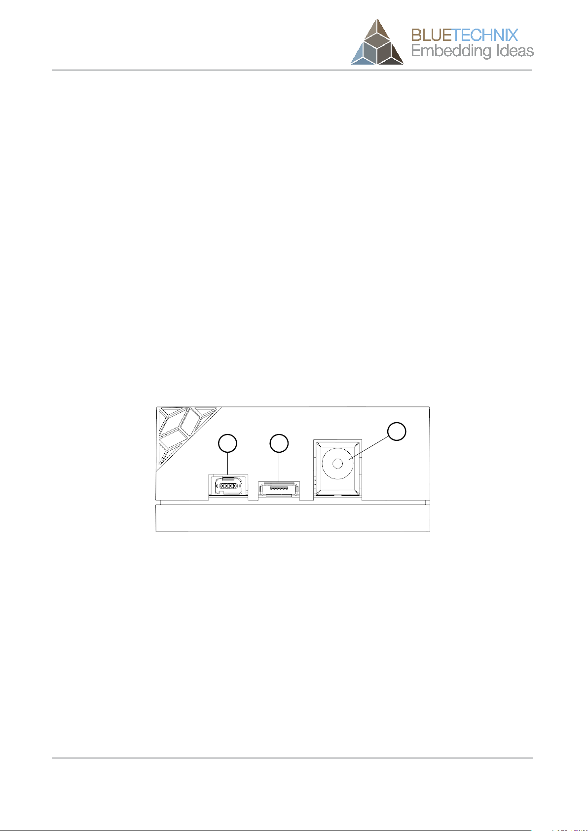
1.2.1 Connector Overview
The Argos3D - P100 features three connectors. A 5VDC@2.5A connection, Micro USB2.0 and an external sync
interface.
a b
c
Figure 1-1: Connector Overview
a. Modulation Light Interface
b. Micro USB 2.0 Interface
c. Power Connector
NOTE: Please follow the next steps in the right order to get your ‘P100’ up and running correctly.
© Bluetechnix 2014 Page 5 | 22
Quick Start Guide - Argos3D - P100
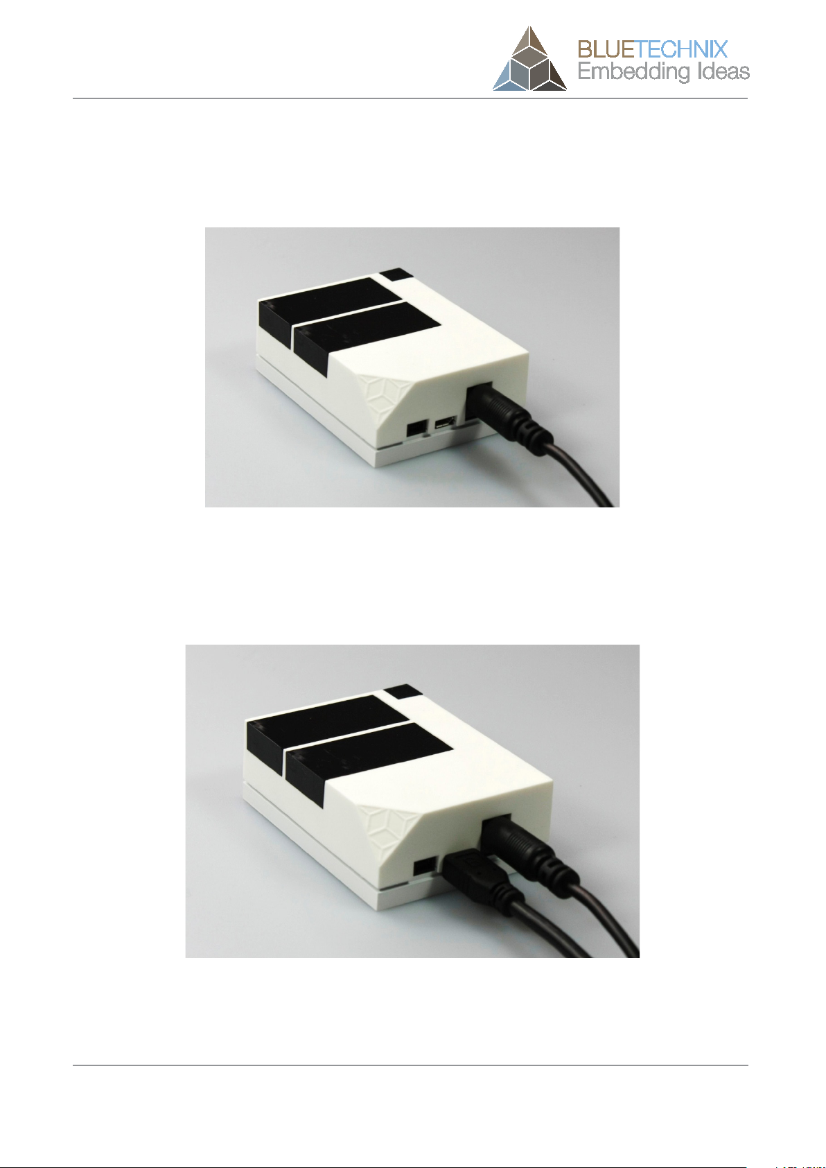
1.2.2 Connecting the power supply
To ensure, that your Argos3D - P100 works correctly, plug in the power supply and wait for approximately 10
seconds until the camera boots up.
Figure 1-2: Connecting Power Supply
1.2.3 Connecting USB2.0 cable
After boot up, plug in the micro USB2.0 cable and connect your Argos3D - P100 to a free USB port of your
PC.
Figure 1-3: Connecting USB2.0 cable
© Bluetechnix 2014 Page 6 | 22
Quick Start Guide - Argos3D - P100
2Evaluation Package
The Argos3D - P100 Evaluation Package containing of the SDK, Visualizer, documentation etc. can be found
on the enclosed Support CD. For updates register on our support website at
https://support.bluetechnix.com/ and download the latest version of the Evaluation Package for your
Argos3D - -- P100.
‘‘ADAF Basic’’ is included on a separate CD.
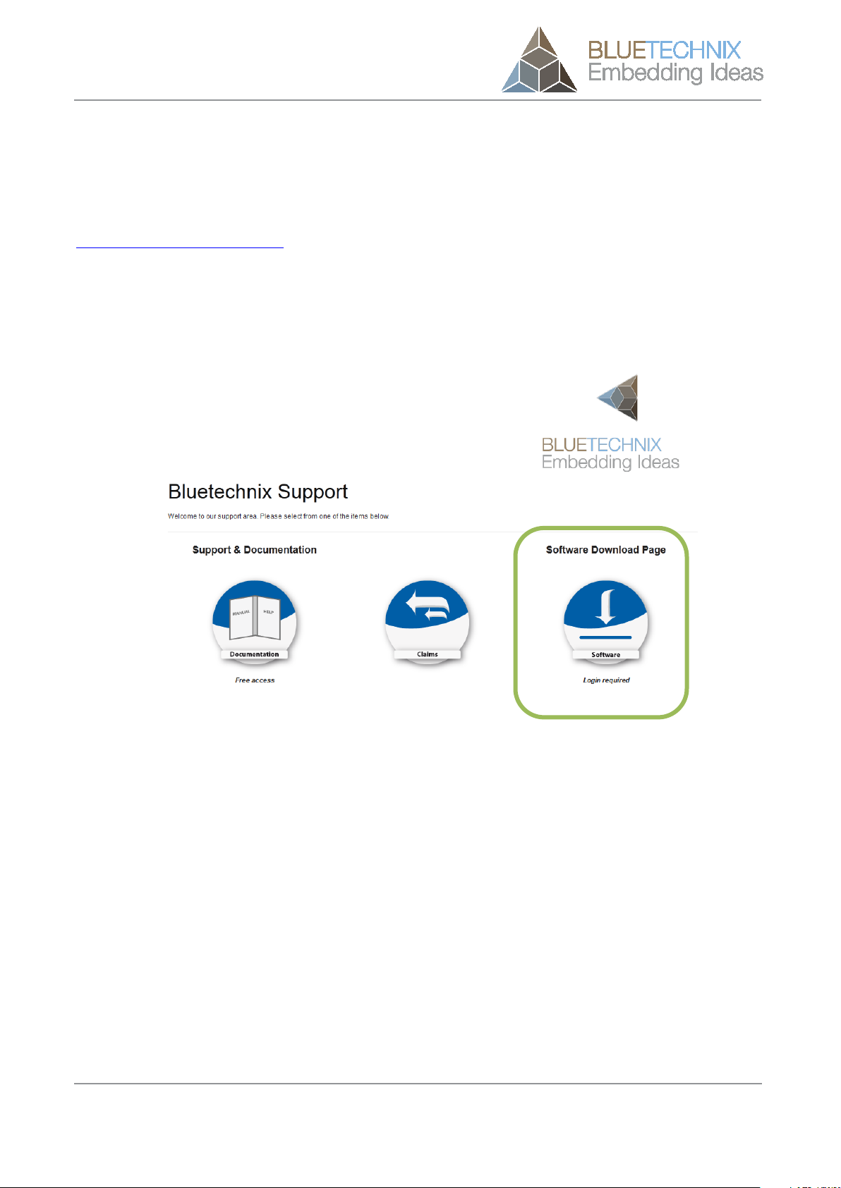
2.1 Support website
Figure 2-1: Download Evaluation Package
© Bluetechnix 2014 Page 7 | 22

Quick Start Guide - Argos3D - P100
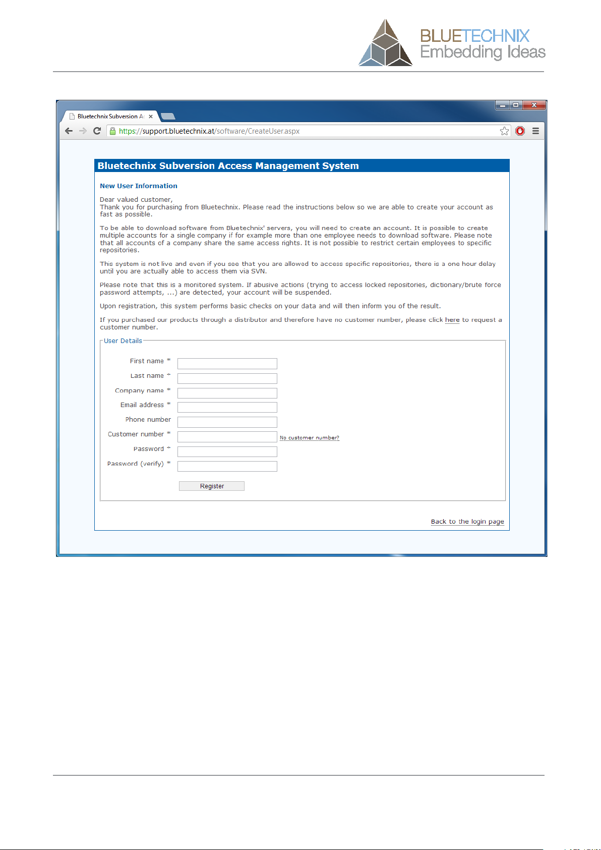
Figure 2-3: Registration form
© Bluetechnix 2014 Page 9 | 22
Quick Start Guide - Argos3D - P100
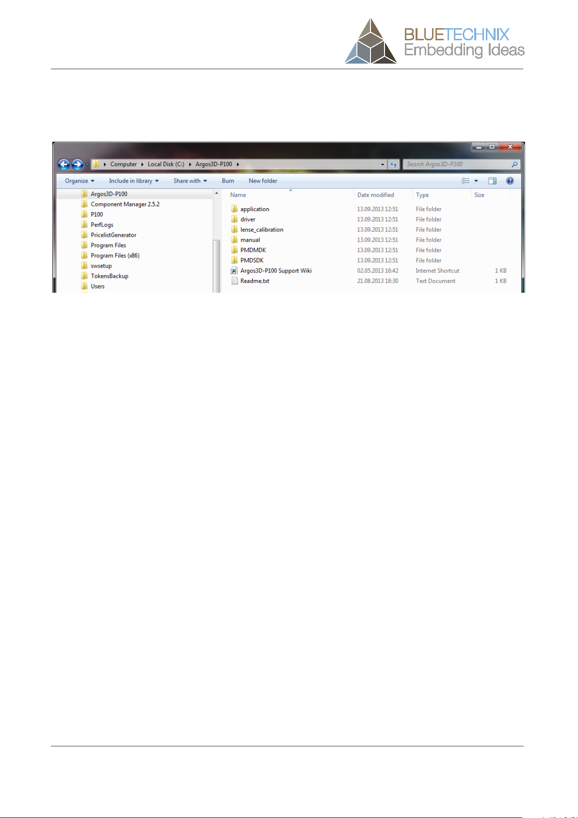
Once you downloaded the evaluation package extract the .zip file on your hard drive to e.g.
C:\Argos3D-P100\and read the Readme.txt first.
Figure 2-4: Unzipped Evaluation Package
© Bluetechnix 2014 Page 10 | 22

Quick Start Guide - Argos3D - P100
3Install Argos3D - P100 Drivers
At the first time you have plugged in your Argos3D - P100, you have to install the driver which can be found in
the evaluation package.
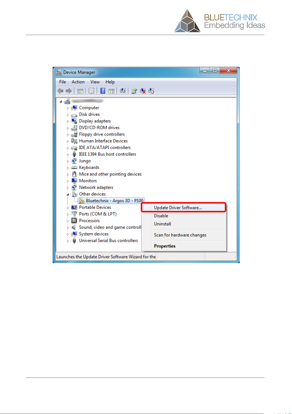
Open the Windows Device Manager by pressing the Windows-Button + Pause-Button and choose Device
Manageras shown in following figure.
Figure 3-1: Windows Device Manager
© Bluetechnix 2014 Page 11 | 22
Quick Start Guide - Argos3D - P100
Once Device Manager is opened, right click ‘‘Bluetechnix - -- Argos3D - -- P100’’ in ‘‘Other Devices’’ and click
‘‘Update Driver Software’’.
Figure 3-2: Device Manager - -- Update Driver Software
© Bluetechnix 2014 Page 12 | 22

Quick Start Guide - Argos3D - P100
Then choose ‘‘Browse my computer for driver software’’.
Figure 3-3: Locate and install driver software manually
© Bluetechnix 2014 Page 13 | 22

Quick Start Guide - Argos3D - P100
Point the driver install utility to ‘‘C:\Argos3D-P100\windows\driver’’ on your local hard drive. Check ‘‘Include
subfolders’’ and click ‘‘Next’’.
Figure 3-4: Browse for driver software on your computer
© Bluetechnix 2014 Page 14 | 22

Quick Start Guide - Argos3D - P100
If the Windows Security warning appears choose ‘‘Install this driver software anyway’’.
Figure 3-5: Driver security warning
© Bluetechnix 2014 Page 15 | 22

Quick Start Guide - Argos3D - P100
The Update Driver Software Utility finishes the driver installation showing following Window.
Figure 3-6: Driver Software successfully installed
© Bluetechnix 2014 Page 16 | 22
Quick Start Guide - Argos3D - P100
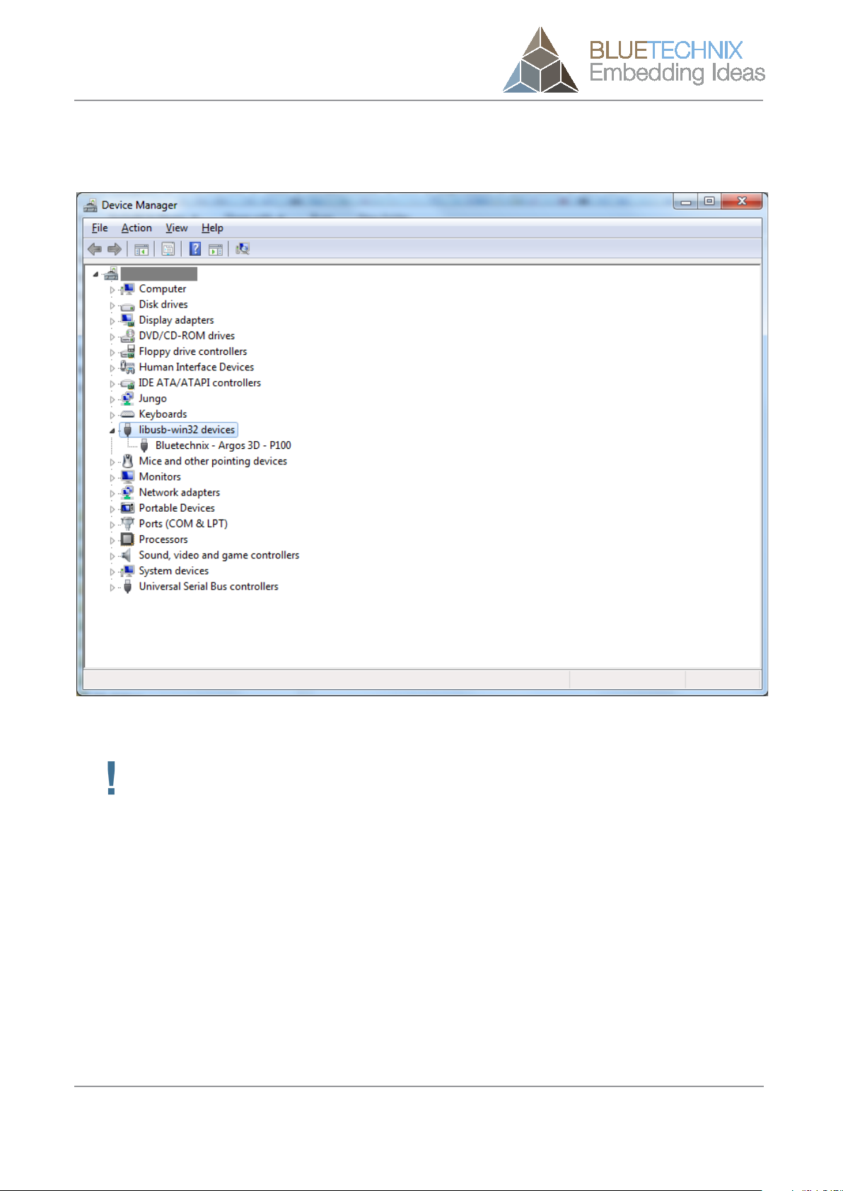
After successful driver installation there should be a new device in the device manager named ‘‘Bluetechnix -
Argos 3D - P100’’.
Figure 3-7: Bluetechnix PMD Devices in Device Manager
Congratulations
You now have successfully installed your Argos3D - P100 on your PC.
© Bluetechnix 2014 Page 17 | 22
Quick Start Guide - Argos3D - P100
4Start using your Argos3D - P100 with ‘‘Visualizer’’
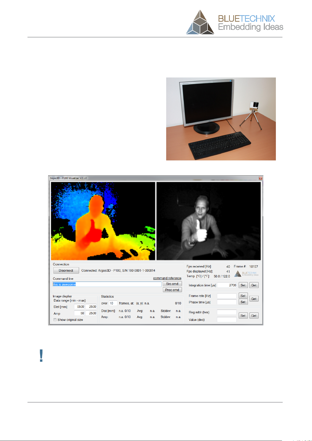
When you browse to
‘‘C:\Argos3D-P100\application\Visualizer\bin\x64’’
(64Bit Windows) or
‘‘C:\Argos3D-P100\application\Visualizer\bin\x86’’
(32Bit Windows)
you’ll find Argos3D - P100 Visualizer.exe. Using
this software you can simply display the depth image
and the amplitude image of the Argos3D - P100.
Mount the Argos3D - P100 on the provided tripod and
place it on your desk in front of you.
Figure 4-1: Sample scenario with Argos3D - P100
Figure 4-2: Visualizer GUI
Important
The default configuration of your Argos
3D
- P100 is set to capture scenes in approximately 1.5m
with 40 frames per seconds. For other configurations refer to the User Manual of Argos3D -
P100.
© Bluetechnix 2014 Page 18 | 22

Quick Start Guide - Argos3D - P100
4.1 Working with ‘‘Visualizer’’
Figure 4-3: Visualizer screenshot with description
4.1.1 Connection (1)
Press the ‘‘Connect / Disconnect’’ button for connecting or disconnecting the sensor.
4.1.2 Applying source- and process-commands (2)
To apply source- or process-commands use the text-field from section 6 (see Figure 4-3). After the
command has been entered press the ‘‘Src cmd’’ or the ‘‘Proc cmd’’ button for applying either a source- or a
process-command.
For a list of source and process commands please click ‘‘command reference’’ and refer to our support site
at https://support.bluetechnix.com/wiki/Argos
4.1.3 Changing the color range (3)
To adjust the color range to a certain setup or scene use the min and max text-fields in the ‘‘Image display’’
section (3) (see Figure 4-3). Type in the minimum distance and amplitude expected and the maximum
distance and amplitude expected. The color scheme will then be expanded from red to blue for the distance
image and from black to white for the amplitude image, between the selected minimum and maximum.
1
2
3
4
5
6
7
8
© Bluetechnix 2014 Page 19 | 22

Quick Start Guide - Argos3D - P100
4.1.4 Statistics (4)
The statistics section shows the average (Avg) of the amplitude and the distance over a certain number of
frames. In addition the standard deviation (Stddev) is shown. To see the statistics of a certain pixel just move
the mouse over the pixel of interest (either in the distance or the amplitude window) and wait until the
selected number of frames have been received. If you move the mouse the buffer is cleared.
4.1.5 Status Information (5)
The status information shows the current number of received frames per second (fps received), the frames
drawn per second (fps drawn) the current frame number and the temperature of the LED-Board (Led).
Be aware that the frames drawn may be significantly lower than the frames received. This because the
application is not able to show the frames as fast as they are delivered by the camera. It depends on the PC
configuration how many frames can be processed per second.
4.1.6 Changing the integration time (6)
To change the integration time, type the integration time in µs in the text-field and press the ‘‘set’’ button. To
control the integration time currently set, press the ‘‘get’’ button.
The text-field becomes green if the operation was successful, red otherwise.
4.1.7 Changing the frame rate (7)
The frame-rate can be changed using section 7 (see Figure 4-3).
You can enter your required fps directly to the associated text field. As an alternative you can enter the
required phase time.
Phase Time [µs] = 1 / (4 x fps [Hz] )
The text-field becomes green if the operation was successful, red otherwise.
4.1.8 Generic register read/write (8)
To write or read any register from the camera use section 8 (see Figure 4-3). Type in the register address as
hexadecimal value and the content as decimal value, then press the ‘‘set’’ button.
To read a register enter the register address as hexadecimal value and press the ‘‘get’’ button. The register
content should be shown as decimal value in the ‘‘´Value’’ text-field.
The text-field becomes green if the operation was successful, red otherwise.
© Bluetechnix 2014 Page 20 | 22
Other manuals for Argos3D - P100
2
Table of contents
Other Blue Technix 3D Camera manuals


