EPC TOFcam-635-S User manual

TOFcam-635-S
Installation and Operation Manual
General description
The TOFcam-635-S is a miniaturized and cost-optimized 3D TOF
camera. It is based on the ES ROS proprietary time-of-flight (TOF)
technology using the epc635 chip. The camera controls the illumi-
nation and the imager chip to obtain distance and grayscale
images. The cameras are calibrated to provide accurate 3D depth
information. The depth images are compensated against DRNU
errors, modulation errors, temperature, ambient-light and reflec-
tivity of the scene. Its extremely wide field of view of 120° allows a
variety of new applications e.g. for mobile robotics or entrance
controls.
This document allows a TOFcam-635-S user easily to get the
camera connected and started using a computer. It contains a
description of all features, commands, protocols and interfaces of
the device. This allows to connect the module to integrated
systems. The optional software development kit (SDK) contains the
camera operating system (TOFCOS) with all C++ source codes.
Together with the ES ROS epc635 evaluation kit this is the perfect
environment to develop embedded software or even an application
specific camera.
Features
■160 x 60 pixels resolution
■Field of view of 120° x 25° for TOF images
Field of view of 120° x 45° for gray scale images
■Distance measurement ranges on white target: 5cm … 3m
■Measurement rate up to 20 TOF measurements per second
■Fully calibrated and compensated
■USB interface
■High speed serial interface UART 10 Mbit/s
■Two I/O versions available
■Low power consumption
■Various user interfaces: GUI, ROS, ython
□Evaluation of TOFcam-635-S features
□rogramming of I/O properties
□Store and recall camera configurations
□Many explanations about “time of flight done right”
Typical applications
■Research in various scientific fields
■IoT applications
■Sensing in general
■Mobile robots, automatic vehicle guidance, collision avoidance
© 2020 ES ROS hotonics Corporation
Characteristics subject to change without notice
1 / 51 Installation_and_Operation_Manual_TOFcam635-S_V0.10
www.espros.com
TOF distance FoV: 120° x 25°
Operating range: 5cm … 3m
Gray scale FoV: 120 x 45°
Operating range: 5cm … 3m
Figure 2: TOF and gray scale field definition
Figure 1: TOFcam-635-S
Figure 3: Distance scope for pixel row selection

Contents
1. Before you start .......................................................................................................................................................... 4
1.1. recaution and Safety ...........................................................................................................................................................................4
1.2. Updates..................................................................................................................................................................................................4
1.3. Important Notes......................................................................................................................................................................................4
. Abbreviations............................................................................................................................................................... 5
3. Quick guide ................................................................................................................................................................. 6
3.1. Connecting the camera module ............................................................................................................................................................6
3.2. Camera settings ....................................................................................................................................................................................6
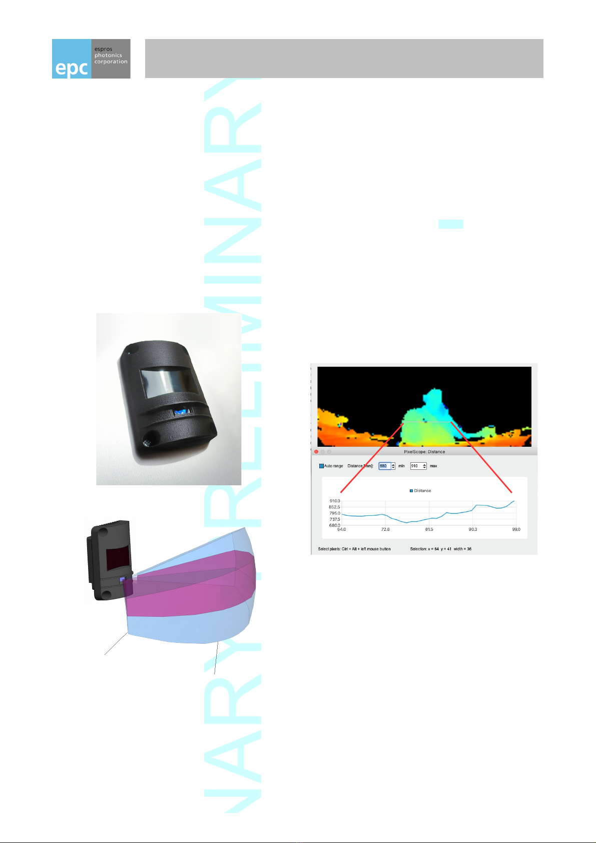
4. TOFcam-635-S time of flight camera module ..........................................................................................................7
4.1. System overview and use cases ...........................................................................................................................................................7
4.2. Scope of delivery ...................................................................................................................................................................................8
4.3. Ordering information ..............................................................................................................................................................................8
4.4. Technical data .....................................................................................................................................................................................10
4.5. Mechanical data ..................................................................................................................................................................................11
4.5.1. Mechanical features ............................................................................................................................................................................11
4.5.2. Mechanical dimensions .......................................................................................................................................................................11
4.5.3. Mounting plane ....................................................................................................................................................................................12
5. GUI ............................................................................................................................................................................. 13
5.1. ut the camera into operation .............................................................................................................................................................13
5.1.1. USB interface ......................................................................................................................................................................................13
5.1.2. UART interface ....................................................................................................................................................................................13
5.2. GUI main window ................................................................................................................................................................................13
5.2.1. View Menu ...........................................................................................................................................................................................14
5.2.2. lay menu ............................................................................................................................................................................................16
5.2.3. Live image window...............................................................................................................................................................................16
5.2.4. Decided information windows .............................................................................................................................................................18
5.2.5. Input readout and Output Control menu .............................................................................................................................................20
5.2.6. Configurations and firmware upgrade menu........................................................................................................................................20
6. Operating the device with a ROS ............................................................................................................................ 1
6.1. ROS camera driver...............................................................................................................................................................................21
6.1.1. What is ROS?.......................................................................................................................................................................................21
6.1.2. Installation............................................................................................................................................................................................21
6.1.3. Running the ROS driver.......................................................................................................................................................................21
6.2. ROS A I...............................................................................................................................................................................................22
6.2.1. Start of the node...................................................................................................................................................................................22
6.2.2. ublished topics...................................................................................................................................................................................22
6.2.3. Dynamically reconfigurable parameters...............................................................................................................................................23
7. Operating the camera with the Python Framework................................................................................................ 4
7.1. Script example .....................................................................................................................................................................................24
7.2. Comport................................................................................................................................................................................................24
7.3. Resulting data frame ...........................................................................................................................................................................24
7.4. Toolchain:.............................................................................................................................................................................................24
8. Operating the device by UART interface ................................................................................................................ 5
8.1. Sensor interface ..................................................................................................................................................................................25
8.1.1. Connector ............................................................................................................................................................................................25
8.1.2. in table for TOFcam-635-S-UWF-850-E ...........................................................................................................................................25
8.1.3. in table for TOFcam-635-S-UWF-850-R ...........................................................................................................................................26
8.2. Communication interface......................................................................................................................................................................26
8.2.1. Hardware interface...............................................................................................................................................................................26
8.2.2. Software interface................................................................................................................................................................................26
8.2.3. Command format..................................................................................................................................................................................27
8.2.4. Response format..................................................................................................................................................................................27
8.2.5. CRC checksum.....................................................................................................................................................................................28
8.2.6. Acknowledge ACK (response).............................................................................................................................................................28
8.2.7. Error handling.......................................................................................................................................................................................28
8.3. Command set overview........................................................................................................................................................................29
8.3.1. SET commands....................................................................................................................................................................................29
8.3.2. GET commands...................................................................................................................................................................................30
8.3.3. Miscellaneous commands....................................................................................................................................................................31
8.3.4. Factory maintenance commands.........................................................................................................................................................32
8.4. SET commands ...................................................................................................................................................................................33
8.4.1. SET_MOD_CHANNEL [0x0E] ..........................................................................................................................................................33
8.4.2. SET_INT_TIME_DIST [0x00] ............................................................................................................................................................34
8.4.3. SET_INT_TIME_GS [0x01] ...............................................................................................................................................................34
8.4.4. SET_HDR [0x0D] ..............................................................................................................................................................................35
© 2020 ES ROS hotonics Corporation
Characteristics subject to change without notice
2 / 51 Installation_and_Operation_Manual_TOFcam635-S_V0.10
www.espros.com

8.4.5. SET_ROI [0x02] ................................................................................................................................................................................35
8.4.6. SET_TEM ORAL_FILTER_WFOV [0x07] .......................................................................................................................................36
8.4.7. SET_AVERAGE_FILTER [0x0A] ......................................................................................................................................................36
8.4.8. SET_MEDIAN_FILTER [0x0B] ..........................................................................................................................................................36
8.4.9. SET_INTERFERENCE_DETECTION [0x11] ...................................................................................................................................37
8.4.10. SET_EDGE_DETECTION [0x10] ......................................................................................................................................................38
8.4.11. SET_FRAME_RATE [0x0C] ..............................................................................................................................................................38
8.4.12. SET_AM LITUDE_LIMIT [0x09] .......................................................................................................................................................38
8.4.13. STO _STREAM [0x28 ] ....................................................................................................................................................................38
8.4.14. SET_COM ENSATION [0x55] .........................................................................................................................................................38
8.4.15. SET_DLL_STE [0x06] .....................................................................................................................................................................38
8.5. GET commands...................................................................................................................................................................................40
8.5.1. Acquisition modes................................................................................................................................................................................40
8.5.2. Acquisition data output formats............................................................................................................................................................40
8.5.3. Response header.................................................................................................................................................................................41
8.5.4. Warm-up...............................................................................................................................................................................................42
8.5.5. GET_DIST [0x20] ..............................................................................................................................................................................43
8.5.6. GET_DIST_GS [0x29] .......................................................................................................................................................................43
8.5.7. GET_DIST_AM LITUDE [0x22] .......................................................................................................................................................43
8.5.8. GET_GS [0x24] .................................................................................................................................................................................44
8.5.9. GET_DCS [0x25 ] ..............................................................................................................................................................................44
8.5.10. GET_CALIBRATION_INFO [0x57 ] ..................................................................................................................................................44
8.6. Miscellaneous commands....................................................................................................................................................................45
8.6.1. SET_OUT UT [0x51] ........................................................................................................................................................................45
8.6.2. GET_IN UT [0x52] ...........................................................................................................................................................................45
8.6.3. GET_TEM ERATURE [0x4A] ..........................................................................................................................................................45
8.6.4. GET_TOFCOS_VERSION [0x49] .....................................................................................................................................................45
8.6.5. GET_CHI _INFORMATION [0x48] ..................................................................................................................................................45
8.6.6. GET_ ROD_DATE [0x50] ................................................................................................................................................................46
8.6.7. IDENTIFY [0x47] ...............................................................................................................................................................................46
8.7. GET_ERROR [0x53] .........................................................................................................................................................................46
8.8. Factory maintenance commands ........................................................................................................................................................47
8.8.1. CALIBRATE_DRNU [0x41] ...............................................................................................................................................................47
8.8.2. GET_CALIBRATION [0x43] ..............................................................................................................................................................47
8.8.3. JUM _TO_BOOTLOADER [0x44] ....................................................................................................................................................47
8.8.4. U DATE_TOFCOS [0x45] ................................................................................................................................................................48
8.8.5. WRITE_CALIBRATION_DATA [0x4B] ..............................................................................................................................................48
8.8.6. SET_MOD_FREQUENCY [0x05] .....................................................................................................................................................48
8.9. Update camera operating system TOFCOS .......................................................................................................................................49
9. Maintenance and disposal........................................................................................................................................ 50
9.1. Maintenance.........................................................................................................................................................................................50
9.2. Disposal................................................................................................................................................................................................50
10. Addendum ................................................................................................................................................................. 51
10.1. Related documents .............................................................................................................................................................................51
10.2. Links ....................................................................................................................................................................................................51
10.3. Licenses ..............................................................................................................................................................................................51
11. IMPORTANT NOTICE................................................................................................................................................. 5
© 2020 ES ROS hotonics Corporation
Characteristics subject to change without notice
3 / 51 Installation_and_Operation_Manual_TOFcam635-S_V0.10
www.espros.com

1. Before you start
1.1. Precaution and Safety
This product is eye safe according to IEC62471-2013.
The camera module is an electronic device. Handle it with the necessary ESD precaution.
Over-voltage: Use only a power supply which correspond to the datasheet of the camera to avoid damage of the device
or cause danger for humans.
Cable-tripping: lace or mount the sensor on solid ground or fix it correctly on a solid support. lace cables carefully.
Falling devices can be damaged or harm persons.
The camera comes with its own calibrated TOFCOS. Do not alter the TOFCOS without obeying the instructions herein.
Be careful to the window surfaces of the camera. Never use any solvents, cleaners or mechanically abrasive towels or
high pressure water to clean the sensor.
Operate the device in compliance with the local EMC regulations.
This camera is not a safety device. It may not be used in safety applications, explosive atmospheres or in radioactive
environment, except the user implements the required safety measures, e.g. by redundancy. However, the sole respon-
sibility for the safety of the application is by the user.
LIMITED WARRANTY - LOSS OF WARRANTY
This camera should only be installed and used by authorized persons. All instructions in this datasheet and in the
related documents shall be followed and fully complied with. In addition, the installer and user is required to comply with
all local laws and regulations. The installer and user is fully responsible for the safe use and operation of the system. It
is the sole responsibility of the installer and the user to ensure that this product is used according to all applicable codes
and standards, in order to ensure safe operation of the whole application. Any alteration to the devices by the buyer,
installer or user may result in device damage or unsafe operating conditions. ES ROS hotonics AG is not responsible
for any liability or warranty claim which results from such manipulation or disregarding of given operating instructions.
ES ROS hotonics AG is an ISO 9001: 2015 certified company.
This product is according to European Union standards and free of hazardous substances.
1. . Updates
ESPROS Photonics is constantly striving to provide comprehensive and correct product information. Therefore, please check
ESPROS' website regularly for updated versions of datasheets and documentations: www.espros.com
Download the latest Flyer TOFcam-635.
Download the latest “Installation and Operation Manual TOFcam-635-S”.
Download and use the latest software package “TOFCAM635-S_SW_ ackage” containing a graphical user interface
(GUI) for Windows, Mac or Linux computers, a robot operating system (ROS) application and a ython A I framework.
The current firmware “TOFCOS” is part of the GUI which allows an easy upgrade of the camera with current firmware.
If there are any questions, please contact your ES ROS sales office or send an email to sales@espros.com.
Download and use the latest software development kit (SDK) “TOFCAM635-S_SDK” containing all source codes of the
firmware, GUI, ROS and A I. Unpacking the SDK is password protected. Get back to ES ROS to check whether you
fulfill the requirements to get the password.
1.3. Important Notes
Notes on PRELIMINARY versions:
THIS MANUAL IS UNDER CONSTRUCTION. IMPORTANT PARTS MAY BE MISSING
Colored marking in text means “under consideration” and refers to not yet applicable or verified information.
Values and/or information are either estimates or show the applicable principle only.
© 2020 ES ROS hotonics Corporation
Characteristics subject to change without notice
4 / 51 Installation_and_Operation_Manual_TOFcam635-S_V0.10
www.espros.com

. Abbreviations
Designator Description
3D Three dimensional
ACK Acknowledged
A I Application program interface
ADC Analog-to-digital converter
Binning Summation of a defined number of pixels. Binning can be done in the charge (analog) or in the digital domain
CMD Command
CRC Cyclic redundancy check (checksum)
DCS Differential correlation sample
DLL Delay locked loop, controllable delay line
DRNU Distance response non-uniformity: Distance error from pixel to pixel with a target at the same distance
EMC Electromagnetic compatibility
EMI Electromagnetic interference
ESD Electrostatic discharge
FoV Field of view
fps Frame rate, number of images per second
Frame One image
GND Ground terminal, negative supply voltage
GS Grayscale
GUI Graphical user interface
HDR High dynamic range
ID Identifier
IN Input terminal which is used to sense a high or low voltage
ISO International organization for standardization
JEDEC Joint electron device engineering council
LED Light emitting diode used to illuminate the scenery or as indicator
LSB Least significant bit / byte
LVTTL Low voltage transistor transistor logic
MSB Most significant bit / byte
NACK Not acknowledged
OUT Output terminal which is can be set to high or low voltage
RMS Root mean square
RoHS Restriction of hazardous substances
ROI Region of interest in the pixel-field
ROS Robot operating system
RX Receive terminal, data in
SW Software
TBD / tbd To be defined, information not yet available or not valid
TOF Time of flight
TOFCOS TOF camera operating system, firmware in the camera
TTL Transistor transistor logic
TX Transmit terminal, data out
UART Universal asynchronous receiver transmitter
USB Universal Serial Bus
VDD ositive supply voltage
Table 1: List of abbreviations used in this document
© 2020 ES ROS hotonics Corporation
Characteristics subject to change without notice
5 / 51 Installation_and_Operation_Manual_TOFcam635-S_V0.10
www.espros.com

3. Quick guide
3.1. Connecting the camera module
First of all you need to prepare a power supply to supply the camera
with power. Therefore use the 8 pin connector which is included in the
scope of delivery. If you ordered the power supply and power adapter
cable as accessory according to Chapter 4.3 then you don't need to
provide a separate power supply connected to this 8 pin connector.
You need to install the Graphical User Interface onto your computer.
This is available with the "TOFCAM635_SW_ ackage" from our
download page.
•Connect the camera to your computer with a USB cable.
•Connect the camera to proper voltage using the prepared or
ordered power supply.
•Start the GUI on your Computer. The connection to the camera will be indicated in the corner bottom left of the main window of
the GUI (Connected).
3. . Camera settings
•Choose Image Type "Distance"
•Disable “Automatic Integration Time 3D” and switch “HDR off”
•Set “Offset” and “Distance Min” values to zero and the
"Distance Max" to the effective maximum distance in your
scenery.
•For object detection set the "Amplitude" limit 0” to 50 LSB, for
accurate measuring to 200 LSB (this are good starting points,
fine-tuning possible). Start streaming with the “Start” button.
•Increase / decrease the "Integration Time 3D 0" to a value
where you get a distance picture of the most far objects you
would like to see.
•Swith to “HDR temporal” and set “Integration Time 1 … 3” to
zero. increase the "Integration time 3D 1" to a value where
saturation (purple), ADC overflow (pink) and invalid (black)
pixels are removed or reduced to a minimum (normally this
value is about 10 ... 20% of the "Integration time 3D 0" value).
•lay with filtering: enable "Temporal Filter" e.g.
•Optimize the color scale (visual graduation) of the relevant
objects in your scenery by changing the "Distance Range
min." value.
•Change the image type to the illustration of the scenery you
like to see.
•Swith on the additional “Info” and “Scope” windows which
delivers you valuable information.
© 2020 ES ROS hotonics Corporation
Characteristics subject to change without notice
6 / 51 Installation_and_Operation_Manual_TOFcam635-S_V0.10
www.espros.com
Figure 4: 8-pin power-supply , UART and G IO connector
Figure 5: GUI window for camera settings

4. TOFcam-635-S time of flight camera module
4.1. System overview and use cases
The TOFcam-635-S is a camera and sensor module based on the ES ROS epc635 cwTOF imager chip:
•24VDC power supply input
•STM32F466 ARM microcontroller
•The micro controller board communicates with the epc635 chip carrier board through an ultrafast TCMI serial interface.
•An ultra wide field lens focus the reflected light from the scenery onto the pixel field of the imager chip
•NIR band pass filter, AR coatings and straylight suppression for optimal optical performance
•LED illumination
•TOF camera operating system (TOFCOS) for camera control, distance calculation and filtering
•Two sensor versions are available with one relay or three digital outputs
•Communication by USB or UART
•Application programming interface (A I) for further processing is available. It opens the world for using open source tools or
creating own customer applications.
•ROS device drivers for Linux available
•Windows, Mac and Linux GUI available
© 2020 ES ROS hotonics Corporation
Characteristics subject to change without notice
7 / 51 Installation_and_Operation_Manual_TOFcam635-S_V0.10
www.espros.com
Figure 6: Use case overview
A I
UART
A I
HW I/O
Sensor
firmware
TOFCOS
Internet
TOF Sensor TOF camera Integrated TOF module
Open Source
Tools
Customer
Application
Connected for operation
Connected for programming

4. . Scope of delivery
Pieces Part Name Picture
1 Time of Flight Sensor TOFcam-635-S consisting of:
–Molded housing
–Receiver lens
–Illumination with lens
–Electronics board
1 8 pin connector plug with L = 75mm open end cable for 24V power
supply, UART interface and G IO
–lug with 8 pin open cable ends
–Connecting instructions
–in assignment
1 Software package containing GUI, ROS, ython A I and current
Firmware. Available on the ES ROS download page.
1 Documentation
(useful additional information available on the Espros download page )
Table 2: Scope of delivery
4.3. Ordering information
Picture Part No. Name Description
100 651 TOFcam-635-S-UWF-850-E Camera with 1x digital input and 3x digital
output (0 … 24V)
100 623 TOFcam-635-S-UWF-850-R Camera with 1x digital input and 1x relay
output NO/NC
100 664 8 pin connector plug with open cable ends
(L = 75mm)
Included in TOFcam-635-S basic unit.
To connect the camera to a corresponding
power supply.
100 660 ower supply 24VDC Input 100 … 240VAC, 50 / 60Hz
Output 24VDC, 500mA
Including camera connection cable
© 2020 ES ROS hotonics Corporation
Characteristics subject to change without notice
8 / 51 Installation_and_Operation_Manual_TOFcam635-S_V0.10
www.espros.com

4.4. Technical data
All characteristics are at typical operational ratings, TA = +25ºC, VDD / VDDLED = 5V, object reflectivity 90%, unless otherwise stated.
Parameter Description Conditions Min. Type Max. Units Comments
VDD Main supply voltage Ripple 1 < 50 mVpp 4.75 5.0 5.25 V
IDD Main supply current Acquisition 140 mA
Idle 100 mA
λ Operating wavelength 850 nm
RESIMAGE Image resolution 160 x 60 ixel
FOV Field of view TOF FOV 120 x 25 ° 160 x 35 pixels
GS FOV 120 x 45 ° 160 x 60 pixels
D Operating range 0.05 3 m Depends on integration time
DUnabiguity Unambiguity range 27.25 7.5 7.8 m Depends on mudulation
channel
Acc Accuracy 0.05 … 1.0 m ± 2 cm Mean of 100 samples
1.0 … 3.0 m ± 2 %
DNOISE Distance noise (1σ value) 0.1 mm Amplitude 100 ... 1'900 LSB,
Kalman Filter k = 10 and
threshold t = 300 mm,
ambient-light less than
10 kLux on target
tINT Integration time selectable 1 1000 µs Default: 125µs
tCYCLE Measurement cycle time GET_DIST
GET_DIST_AM LITUDE
50
72
ms
ms
@tINT = 125µs, single
measurement, including data
transmission
fMOD Modulation frequency 19.20 20.00 20.70 MHz Refer to Chapter 8.4.1
tWR_U ower up time until acceptance of commands 1.5 s
tWARM_U Warm-up time until output data is in tolerance Refer to Chapter 8.5.4
RESDISTANCE Distance measurement resolution 1 mm/LSB Refer to Chapter 8.5.
ΦAL Ambient-light suppression 100 kLux Indirect, on target
Ee EAK eak illumination irradiance 372 W/m2With 200mm distance to the
front surface of the camera
Ee AVG Average illumination irradiance 108 W/m2With 200mm distance to the
front surface of the camera
VOUT OUT0 / OUT1 / OUT2 voltage (open drain) 36 V Refer to Figure 24
IOUT OUT0 / OUT1 / OUT2 current sink 50 mA Over-current protected
VREL Relay voltage 30
125
VDC
VAC
Refer to Figure 26
IREL Relay current 1
3
A
A
DC
AC
VIN IN input voltage logic low 0 0.8 V Input resistance 100kΩ,
refer to Figure 25
logic high 3.0 30 V
TAAmbient temperature range -20 60 °C Operation and storage
RH Relative humidity 15 90 % Non-condensing
W Weight 43 g Without cable
ESD Electrostatic discharge rating JEDEC HBM class 1C (1kV to < 2kV) Human body model
EMC / EMI EMC emission EN 61000-6-3:2011, EN 61000-6-2:2005
Eye safety IEC62471:2013
Table 4: Technical data
Notes: I
1Min. and Max. voltage values include noise and ripple voltage
2The camera uses the continuous-wave TOF phase-shift measurement technique with a modulation frequency 20MHz. This leads to
unambiguity distances of 7.5m. Highly reflective objects outside of the effective operating range of 7.5m will appear closer due to the
wrap-around of the modulation period. Example: Is the object at a distance of 8.5m, the camera displays a distance of 1m (8.5m -
7.5m). This is obviously wrong !
© 2020 ES ROS hotonics Corporation
Characteristics subject to change without notice
10 / 51 Installation_and_Operation_Manual_TOFcam635-S_V0.10
www.espros.com

4.5. Mechanical data
4.5.1. Mechanical features
4.5. . Mechanical dimensions
© 2020 ES ROS hotonics Corporation
Characteristics subject to change without notice
11 / 51 Installation_and_Operation_Manual_TOFcam635-S_V0.10
www.espros.com
Figure 7: Mechanical features
USB-Connector
Status LED
UART-Connector
Heat sink
Back cover
Front- cover
Illumination window
Mounting plane
Camera Lens
(zero distance)
Mounting holes (4x)
X
Y
Z
12
zero point
Z-axis
Figure 8: Mechanical dimensions
Holes for mounting screws:
4 x ø 3.4 / 6.3mm
Mounting screws:
Shank max. ø = 3.2mm
Head max. ø = 6.0mm
Shank min. length = 6mm

4.5.3. Mounting plane
Notes:
■Because the mounting plate is also a heat sink for the illumination LEDs, it should not be covered by thermal insulating material. Free air
flow shall be provided at any time in order to avoid excessive heat of the camera. The camera temperature can be monitored by reading
the temperature with the command GET_TEM ERATURE (refer to Chapter 8.6.3).
© 2020 ES ROS hotonics Corporation
Characteristics subject to change without notice
12 / 51 Installation_and_Operation_Manual_TOFcam635-S_V0.10
www.espros.com
Figure 9: Hole pattern for mounting the TOFcam-635-S

5. GUI
5.1. Put the camera into operation
Connect the camera to 24V DC using the 8 pin UART interface connector with a suitable 24V power supply according to Chapter 4.3. The
status LED is flashing with 0.5Hz after correct power up of the TOFcam-635-S.
5.1.1. USB interface
Connect the camera with your computer using a USB-A to micro-USB cable. So you can control the TOFcam-635-S using the GUI or
ROS. Start the GUI or ROS to run the camera application. If multiple cameras are physically connected to your computer, select the one
you would like to operate.
5.1. . UART interface
Connecting the required pins for UART interface and optionally the G IO / relay contacts allows the integration of the sensor to a
controller. You will find a description of the interface in Chapter 8.1 and the applicable commands in Chapter 8.2.
5. . GUI main window
A) Icamera type, GUI version, Firmware version, Chip-/Wafer-ID of the epc635 in the camera
B) Connection status:
C) Menu tab
View Chapter 5.2.1
lay Chapter 5.2.2
IoControl Chapter 5.2.5
Save/Load Chapter 5.2.6
D) Controls for the selected menu tab
© 2020 ES ROS hotonics Corporation
Characteristics subject to change without notice
13 / 51 Installation_and_Operation_Manual_TOFcam635-S_V0.10
www.espros.com
Figure 10: Select the device to be connected to
Figure 11: Sections of the GUI main screen
A
B
C
D

5. .1. View Menu
The View menu allows to control the camera and the camera output. Distance, amplitude and gray-scale images can be captured,
streamed or recorded. Detailed information about pixel groups or one single pixel can be illustrated.
•“ icture“ and “Start“ open the “Image“ window according to the selection in the “Image Type” drop-down menu. lease see
Chapter 5.2.3 to read the details about the live image window. The “ icture“ button acquires one single frame while the “Start“
button starts a live stream. It changes its look to “Stop“ which allows terminating the streaming.
•“Record“ function allows to save picture data (one picture per push on the “Image“ button) or as live stream (from “Start“ to
“Stop“ command each). On computers with low performance it might be helpful to enable the “Don't display” function to use all
resources for recording the live stream. The recorded data contains all values according to the selected “Image Type“.
•All the “Show ___“ check boxes open additional windows with dedicated information. You will find additional description about
these functions in Chapter 5.2.4.
© 2020 ES ROS hotonics Corporation
Characteristics subject to change without notice
14 / 51 Installation_and_Operation_Manual_TOFcam635-S_V0.10
www.espros.com
Figure 12: Controls of the camera

•“Modulation channel” allows a shift of the modulation frequency to the main (default) modulation frequency. Multiple cameras
operating in the same scenery (full or partially) with the same modulation frequency will interfere each other which leads to
sporadically wrong distance information. This can be eliminated if the cameras do nit use the same modulation frequency.
•To avoid interference issues due to unknown systems disturbing the sensor a “Interference detection“ can be enabled. Interfered
pixels will be detected automatically and indicated as “invalid data”. By selecting the “use last value“ function the last valid value
is sent for the affected pixel instead of marking it as invalid. This function is also be used to suppress motion blur.
•The “Frame rate limit” can be used to limit the frame rate. The function is active only if the set value is below the maximum frame
rate according to all set camera parameters. The maximum operating frame rate can be displayed in the “Show Info“ window.
The frame rate limit is be useful if a defined frame rate is required. It is also useful to limit the power consumption and/or power
dissipation of the camera. This could happen due to very high frame rate at small ROI.
•Integration time setting allows to define the exposure time to acquire one Differential correlation sample (DCS). Four DCS' are
required for distance acquisition.
•“HDR off“ let's the camera operate with one integration time only.
•“HDR spatial“ operates all odd rows of the imager with the “Integration Time 3D 0“ value and all even rows with the “Integration
Time 3D 1“ value.
•“HDR temporal“ allows using up to 4 different integration time values (integration time values with zero values are ignored). In
this mode one complete image is acquired with each set integration time 3D 0 … 3. After the acquisition of all frames, a new
image is generated from the different frames by using the most confident value (pixel by pixel)l. Due to multiple image acquisi -
tions, this mode reduces the frame rate.
•For each integration time, a minimal amplitude can be set. This is the minimum received signal to provide distance. One should
use low limits for object recognition but high limits for accurate distance measurements. lease investigate the TOF theory to
become familiar with the physical context. A very helpful lecture might be the book “3D-TOF, A guideline to 3D-TOF sensors that
work” by ES ROS hotonics Corp. (author Beat Dede Coi et. al.).
•“Offset“ shifts the zero distance from its original z-axis zero point (refer to Figure 7).
•“Minimum distance“ cuts off all pixels reporting a value closer than this setting. In addition, the color distance scale is adjusted
this setting.
•“Maximum distance“ cuts off all pixels reporting a value beyond this setting. In addition, the color distance scale is adjusted this
setting.
•The color scale visualizes distance of every pixel in the viewer.
•Various powerful filter functions are available.
•The ROI (region of interest) allows to reduce the active pixel field. Only pixels within the selected ROI will be acquired. The
“Default ROI” button resets the ROI to full imager size of 160 x 60 pixels.
•Tooltips are available by moving the cursor either to the corresponding text (refer toFigure 13).
© 2020 ES ROS hotonics Corporation
Characteristics subject to change without notice
15 / 51 Installation_and_Operation_Manual_TOFcam635-S_V0.10
www.espros.com
Figure 13: Tooltip examples

5. . . Play menu
•“ lay” replays the selected stream with the set frame rate. After changing the selection or pushing the “Stop“ button the original
frame rate of the recording is used. The “Start“ button changes its look to “ ause“ after been pushed. Selecting the “ ause“
button interrupts the playback and allows to continue from the same point.
The player can replay the recorded data only with the parameters which has been set during the recording process. This
includes also the “Image Type“ according to the “View“ menu.
•“Stop“ aborts the replay, resets the timer to zero and the frame rate to the recording frame rate.
•“Record“ streams images according to the parameters set in the “View” menu, refer to Chapter 5.2.1.
•“F S” sets the acquisition frame rate (or the replay speed respectively). This value is reset by pressing the “Stop“ button or by
changing the selected log in the list.
•“File name“ defines the file name of the log file. An “underline” character separates this name from the current calendar day
followed by a “minus” separated time stamp.
•“Folder path” defines the log file location. It path can be changed either directly in the input field or with the “Select Folder”
function.
•“Delete all logs“ will delete all logs in the selected folder. “Delete selected log“ deletes the selected log only. All deletions needs
to be confirmed by the user.
5. .3. Live image window
The “Image” window pops-up after a streaming, a replay or a recording has been started from the “View“ or the “ lay“ menu. The window
contains the images according to the selected “Image Type“. A recorded streaming contains only the data which has been selected during
the recording process.
© 2020 ES ROS hotonics Corporation
Characteristics subject to change without notice
16 / 51 Installation_and_Operation_Manual_TOFcam635-S_V0.10
www.espros.com
Figure 14: layer controls

•“Mirror horizontal“ flips the image horizontally.
•“Mirror vertical“ flips the image vertically.
•“Rotate 90°” rotates the image.
•The amplitude can be shown as color coded values (default) or as gray-scale.
•The scope functions allow to show some decided information about one single pixel or a selection of many pixels. A description
about these information can be found in Chapter 5.2.4. The pixel selection can be deleted with right mouse click or by just doing
a new selection.
◦“ ixelinfo“ allows to select a single pixel in the active live image by left mouse click. Current information about this pixel are
shown in the decided information window (Figure 18).
◦“ ixelscope“ shows the distance and amplitude values of a row of pixels (Figure 19).
◦“Timescope“ shows a selection of an ROI in the live image. The ROI is defined with left mouse button. The average of
distance and amplitude values over all selected pixels are shown against time axis (Figure 20).
•“ROI“ selects a region of interest by using the left mouse buton. “Default ROI“ resets the ROI.
© 2020 ES ROS hotonics Corporation
Characteristics subject to change without notice
17 / 51 Installation_and_Operation_Manual_TOFcam635-S_V0.10
www.espros.com
Figure 15: Image types: Distance, Amplitude, Grayscale, DCS
Figure 16: Live view controls

5. .4. Decided information windows
If the “Append“ check box is activated in the “Header information“ window the data for each single frame are added to the file. If it is
disabled just the data from last frame are stored.
© 2020 ES ROS hotonics Corporation
Characteristics subject to change without notice
18 / 51 Installation_and_Operation_Manual_TOFcam635-S_V0.10
www.espros.com
Figure 18: ixel information window
Figure 17: Header information window

Number of frames can be used to compress or stretch time axis. With the “Reset“ function the current data can be deleted.
© 2020 ES ROS hotonics Corporation
Characteristics subject to change without notice
19 / 51 Installation_and_Operation_Manual_TOFcam635-S_V0.10
www.espros.com
Figure 19: ixelScope window
Figure 20: Time Scope window

5. .5. Input readout and Output Control menu
The Output check-boxes allow to manually set an output, the “Read” button detects the Input status. For the corresponding pinning please
see 3.1.
5. .6. Configurations and firmware upgrade menu
“Save configuration and settings“ to the C.
“Load configuration and settings“ from the C.
“Update firmware“ allows to download a mew or different firmware to the camera.
© 2020 ES ROS hotonics Corporation
Characteristics subject to change without notice
20 / 51 Installation_and_Operation_Manual_TOFcam635-S_V0.10
www.espros.com
Figure 21: IO control window
Figure 22: Configurations and Upgrade window
Table of contents
Other EPC 3D Camera manuals