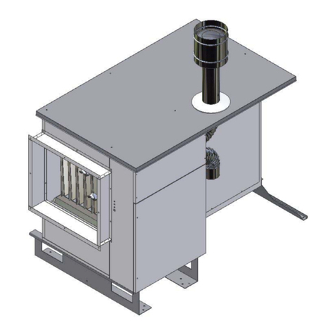
BM2 BIEMMEDUE BMP 26 C Specification sheet

Gas fired room sealed unit heaters
centrifugal
TECHNICAL INFORMATION, ASSEMBLY
INSTRUCTIONS, USE AND MAINTENANCE
BMP C BMP CS BMP C-2 BMP C-2S

2
Dear Customer
Thank you for choosing a BMP C series air heater, an innovative and modern, quality and high performance product which
will assure safe and silent working for a long time. This is particularly the case if the generator is put in the hands of
Biemmedue’s Technical Assistance Department whichis specially trained and equipped to keep it working at
maximum efficiency with low running costs and has a large number of original spares in stock.
This instruction manual contains important instructions and suggestions for simple installation and making the best
possible use of the BMP C air heater.
Thank you again
BIEMMEDUE S.p.A.
COMPLIANCE NOTICES
The warm air heaters comply with the following directives:
• EEC machine directives 98/37/CEE
• EEC gas directive 90/396
• EEC low tension directive 73/23
PIN NUMBER
Notified Body PIN Reference is 0694BN3750
SINGLE STAGE TWO STAGE
STANDARD UP RATED FAN STANDARD UP RATED FAN
Type Model Model Model Model
1 BMP 26 C BMP 26 CS BMP 26 C -2 BMP 26 C -2S
2 BMP 36 C BMP 36 CS BMP 36 C -2 BMP 36 C -2S
3 BMP 46 C BMP 46 CS BMP 46 C -2 BMP 46 C -2S
4 BMP 66 C BMP 66 CS BMP 66 C -2 BMP 66 C -2S
5 BMP 86 C BMP 86 CS BMP 86 C -2 BMP 86 C -2S
6 BMP 106 C BMP 106 CS BMP 106 C -2 BMP 106 C -2S
VERSION SINGLE STAGE
The heater has a single stagegas valve, and a standard centrifugal fan. An optional uprated fan version is availablefor
installations that require higher static pressures.
VERSION TWO STAGE
The heater has a two stage Hi /Lo gas valve, and a standard centrifugal fan. An optional uprated fan version is available
for installations that require higher static pressures.
GUARANTEE
Warm air heaters series BMP C are covered by aSPECIFIC GUARANTEE that starts on the dateof purchase of the
device, which date the buyer should document; if he cannot do this, the guarantee starts on the date of manufacture of
the device.
The guarantee conditions are specified in detail in the GUARANTEE CERTIFICATE, supplied with the device, and we
suggest you read them carefully.

3
INDEX
GENERAL
Description of equipment page. 6
Identification “ 7
Description “ 8
Technical data “ 10
Wiring diagram “ 11
Remote control connections “ 15
FOR THE USER
Operation “ 16
Servicing “ 16
Heater indication lights “ 17
Receipt of product and transport “ 17
Dimension and weight “ 18
FOR THE INSTALLER
Installation “ 20
Installation clearances “ 21
Examples of installation “ 22
Accessories “ 23
Gas connection “ 24
Flue and combustion options “ 25
Electrical control panel and circuit board “ 29
Electrical connections “ 29
TECHNICAL ASSISTANCE SERVICE
Duct connection “ 30
Return air connections “ 31
Protection “ 31
Pre commissioning checks “ 31
Initial start up “ 32
Gas conversion “ 33
Thermostat “ 35
Fan “ 36
Control “ 36
Maintenance “ 37
Fault finding “ 39
The following symbols are used in the manual:
WARNING = where the work to be carried out requires
special care and suitable training
FORBIDDEN = where the action MUST NOT be carried
out
This manual consists of 44 pages.

4
GENERAL NOTES
This Instruction Manual is an integral part of the device
and as such must always be kept with the device. This
also when the heater is sold to another user. The
Manual must therefore be conserved carefully and
consulted attentively before any action. In the case of
damage or loss, you can at any time ask the local After
Sales Service for a copy of the Manual.
After removing the packing, first make sure that the
contents are complete and undamaged.
If the heater does not correspond in any way, contact
the Agency that sold the heater.
Installation of warm air heaters must be carried out by
qualified companies. On completion of the job, they
provide the owner with a declaration of conformity of the
installation correctly carried out, that is according to the
requisites of current applicable Norms and according to
the indications provided by the Manufacturer in this
Instruction Manual.
The heaters have been manufactured for room heating
and they must be used for this purpose, compatibly with
their performance characteristics.
The Manufacturer takes no contractual or extra-
contractual responsibility for damage caused to
persons, animals or property, due to errors in
installation, adjustment and maintenance or due to
improper use.
Excess temperature is damaging to health and
represents a waste of energy.
Avoid leaving rooms closed for long periods of time.
Open the windows periodically to ensure adequate air
change.
During the first start-up, there may be formation of
smells and smoke due to evaporation of the liquid used
to protect the heat exchanger during storage; this is a
normal phenomenon that will disappear after a brief
operation time.
The rooms must be adequately aerated.
On leaving the heater unused for a long period, you
should carry out at least the following operations:
• Turn off the main heater switch and the main plant
switch;
• Close the main fuel supply valve.
If the heater is not used for a long period of time, we
suggest you contact the After Sales Service or other
professionally qualified personnel for restarting.
All heaters must be fitted exclusively with original
accessories. The Manufacturer is not responsible
for any damage caused by improper use of the
heater and by the use of accessories that are not
original.
All references to Law, standards, directives and
technical rules in this manual are to be considered
as informative only and valid at the date of printing
of the Manual. The enforcing of new dispositions or
the alteration of current ones do not create any
Manufacturer obligations towards third parties.
Repairs and maintenance must be carried out by
the After Sales Service or by qualified personnel as
specified in this Manual. Do not alter or tamper with
the heater: this can create dangerous situations and
the Manufacturer will not be responsible for any
damage.
The systems that must be installed (gas or oil pipes,
electrical supplies etc) must be suitably fastened
and must not create obstacles that could cause
tripping.
The Manufacturer is responsible for conformity of
his product to laws, directives and construction
standards current at the date of sale. Knowledge
and observation of legislative instruments and of
standards for the design of systems, and for
installation, operation and maintenance are the
exclusive responsibility of respectively the designer,
the installation personnel and the user.
The Manufacturer is not responsible for failure to
observe the instructions in this Manual, for the
consequences of any operation carried out that is
not specifically foreseen, or for any translations
causing erroneous interpretations.
The heater id designed for operation at the thermal
power and the airflow rate as specified in the
Technical Data Chapter. A thermal power that is too
low and/or an airflow that is too high can lead to
condensation in the fluegases, with consequent
irreparable corrosion to the heat exchanger. A
thermal power that is too high and/or an airflow that
is too low cause abnormal overheating of the heat
exchanger with consequent actuation of the safety
systems and damage to the heat exchanger.

5
GENERAL NOTES
The use of devices that employ electrical energy and/or fuel oil requires the observance of some fundamental safety
rules such as:
Children ad unassisted disabled persons must not use
the warm air heaters.
Do not operate electrical equipment such as switches,
electric household equipment etc if you can smell gas,
fuel or other combustibles.
In this case:
• Open the doors and windows to aerate the room
• Close the fuel supply valves
• Call in quickly the After Sales Service or other
professionally qualified personnel
Do not touch the heater if you are barefoot or if parts of
your body are wet.
Do not carry out any cleaning or maintenance operation
without first deactivating the heater by setting the main
system switch to "OFF" and without first closing the fuel
supply.
Do not alter the safety and adjustment systems without
prior authorisation and indications by the heater
Manufacturer.
Do not pull, detach or twist the electric cables that exit
the heater, even if the heater is not connected to the
electrical supply.
Do not open any doors that access the inside of the
heater without turning the main system switch to "OFF".
Do not abandon or leave available to children the
heater packing materials (cartons, nails, plastic bags
etc), as these are a potential source of danger.
Do not install the heater near flammable material, or in
areas where there is a corrosive atmosphere.
Do not place any object on the heater or push anything
through the grilles in the casing nor in the fluegas ducts.
Do not touch the fluegas ducts as during normal
operation these can reach high temperatures and
represent a hazard.
Do not use any adapters, multiple sockets and cable
extensions for the electrical connection of the heater.
Do not install the heater in the open air nor where it
could be subject to atmospheric events.
Do not install the heater directly in limited spaces
without adequate ventilation, as the burner air suction
can create a pressure drop in the room and
consequently cause serious problems.

6
DESCRIPTION OF EQUIPMENT
Heat exchanger
• Stainless steel construction easily accessible for
inspection and cleaning and maintenance operations.
• Patented exchange elements made in stainless steel
modular sections with large surface area, trapezoidal in
section with swirl impressions for which give thermal
yields of over 90%. The exchange elements have no
welded joints or seams near to the burner flame so as
to avoid exposure of any weak points.
Flue outlet with integral flue venter to assist dispersal of
combustion gasses.
External casing
Encloses all controls giving a good aesthetic appearance
and streamlined look whilst allowing for easy inspection.
The casing consists of removable panels and also
includes:
A burner compartment which is totally sealed off, with an
inspection door;
Radiant heat insulation on the surfaces closest to the heat
exchanger;
Outlet grille for directing the warm air.
Fan assembly
One or two centrifugal fans operated by a single electric
motor via pulleys and belts the motor pulley is adjustable to
give effective cooling of the combustion / heat exchanger.
The position of the fan(s) produce greater effective cooling
of the combustion chamber, optimising the heat exchange
and avoiding overheating.
An up rated fan is also available.
Control and protection equipment
This is electronic with ionisation flame detection and
ignition controls.
The equipment controls and monitors the operation of the
burner in the following sequence.
Checks the differential pressure switch operated by the
flue venter is in the closed position and the flue venter is
working;
Checks the air temperature of the combustion chamber
(below 100ºC)
Opens the gas solenoid valve;
Starts burner ignition;
Detects flame signal from flame probe and allows normal
heater operation.
Failure in any of the above sequence will result in the
control box shutting the gas valve and stopping the heater.
The Heater will go to lockout and can be only be reset
manually by pressing the red light on the front of the
equipment.
Gas solenoid valve
The multifunctional 1 stage gas valve (Single Stage)
and 2 Stage gas valve (Two Stage ) consists of:
• Safety solenoid valve
• A regulatory solenoid valve
• A pressure regulator
• A gas filter
Atmospheric multigas burner assembly
Consisting of:
• Galvanised steel manifold
• Visual monitoring aperture for the electrodes and flame
observation
• 3 or 6 stainless steel burner bars
• Ignition and Detection electrodes
Note: the type 4-5-6 are equipped with two gas manifolds,
each manifold has an ignition electrode.
Control and safety thermostat
The heater is controlled by three thermostats pre set to the
following.
LM Limit thermostat (100°C)
Capillary type. Manual Reset
Act as a safety device and shuts down the burner if the
heater goes to overheat. The yellow light will flash when in
overheat. The LIMIT thermostat is reset by the removal of
the plastic cap situated on the control panel inside the
heater, and manually pressing the reset button, after first
ensuring that the fault has been rectified. (calibrated
at100°C). Replace cap after resetting thermostat.
TR Regulatory thermostat (0 – 90°C)
Capillary type. Automatic reset.
The thermostat monitors the temperature of the airflow and
will shut down the burner if the set level is exceeded
(calibrated at 70°C). Once the fan has sufficiently cooled
the heat exchanger, the burner will automatically relight.
The yellow indication light will flash untill the burner
relights. If this fault persists the cause should be
investigated.
SND Control probe (0 – 40°C)
Connected in series with the thermostat TR. The probe will
start the fan when the temperature reaches 30°C
(approximately 30 seconds from burner ignition). When the
desired room temperature is reached and the burner shuts
down, the probe will allow the fan to run for approximately
3- minutes until the heat exchanger has cooled
sufficiently.
The probe also monitors the operation of the TR
thermostat and if a fault is detected will change the yellow
flashing light to a continous on light. In addition to this the
SND probe monitors the temperature of the return air and
will switch off the fan prior to the 3-4 minute run on time if
the heat exchanger has cooled sufficiently (this avoiding
cold air flow from the heater).
Differential air pressure switch
This switch will shut the gas valve if the flue venter fails or
there is an obstruction in the flue, or in the air inlet
preventing the flue venter from operating.
Flue venter
This consists of a centrifugal fan which
Is run by an electric motor with self-cooling rotor the
cooling air is supplied through a duct pipe situated in the
axial fan air flow.
Indication lights
These consist of three different coloured lights on the front
of the heater:
• Green light – indicates normal working. Illuminates
when the gas solenoid valve opens
• Yellow light – indicates the operation of the LM, TR
and SND thermostat.
• Red light - to indicate lockout of the heater by the
control circuit failure.
• Reset button to reset the lockout
Flue spigot
A flue spigot (100mm) is situated at the rear of the heater
for connection of flue pipes.
Combustion air spigot
A combustion air spigot (100/150mm) with a safety mesh
of less than 16 mm Ø on the rear of the heater allow for
connection of combustion air pipe.

7
IDENTIFICATION
If the TECHNICAL DATA is lost or damaged ask
Manufacturer Technical Department for
duplicate.
Check code and model is as data plate.
Position of data plate
Manufacturer
AIR HEATER
Model
Serial Number
Country PIN
Category Code
Type Year
Nominal Heat INPUT kW
Nominal Heat OUTPUT kW
Air Flow (+15°C) m3/h
Electrical Supply
Electrical Power W
Protection Rating
GAS TYPE
Supply Pressure mbar
Head Pressure mbar
Injector Diameter mm
Gas Consumption m3/h
Packing label position
Code
Model
SerialNo

8
DESCRIPTION
Type 1÷4
NOTE:
Heaters type 1, 2, 3 have a single burner manifold.
Heaters type 4 have two burner manifolds
1. Regulation thermostat SND
2. FAN thermostat TR
3. LIMIT thermostat LM
4. Flue venter inspection door
5. Flue pipe
6. Flue manifold
7. Outlet Grille
8. Controls compartment
9. Heat exchanger
10. Burner plate insulation
11. Gas injector
12. Combustion chamber
13. Gas manifold
14. Burner bars
15. Flue ducting
16. Deflector
17. Green power on light
18. Yellow limit indication light
19. Red light lockout indication
20. Lockout reset
21. Gas inlet connection
22. Electrical connections
23. Combustion intake air spigot
24. Flue spigot
25. Inlet casing
26. Fan Motor
27. Centrifugal Fan
28. Gas Solenoid valve
29. Ignition electrode
30. Gas pressure manifold test nipple
31. Flame detection electrode
32. Flame check aperture
33. Flue venter
34. Air inlet grille
35. Base plate front
36. Rear support

9
Type 5and 6:
NOTE:
Heaters type 5 are supplied with 2 opposing burner manifolds
Heaters type 6 are supplied with 4 opposing burner manifolds
1. Regulation thermostat
2. LIMIT thermostat
3. FAN thermostat
4. Flue venter inspection door
5. Flue pipe
6. Flue manifold
7. Outlet Grille
8. Controls Compartment
9. Heat exchanger
10. Gas manifold
11. Gas injector
12. Combustion chamber
13. Burner plate insulation
14. Burner tubes
15. Ignition transformer
16. Left burner casing
17. Flue ducting
18. Deflector
19. Green power light
20. Yellow limit indication light
21. Red light lockout indication
22. Lockout reset
23. Gas inlet connection
24. Cable grips
25. Combustion intake air spigot
26. Flue spigot
27. Inlet casing
28. Fan Motor
29. Centrifugal Fan
30. Gas Solenoid valve (2 on type 5 and 6)
31. Ignition electrode
32. Gas pressure manifold test nipple
33. Flame detection electrode
34. Flame check aperture
35. Gas pressure manifold test nipple
36. Air inlet grille
37. Rear support
38. Base plate

10
TECHNICAL DATA
DESCRIPTION TYPE UNIT
1 2 3 4 5 6
HEAT OUTPUT 25,4 33,8 46,3 65,0 85,0 104,7 KW
21.844 29.068 39.818 55.900 73.100 90.042 kcal/h
HEAT INPUT 23,0 30,5 41,7 58,6 76,6 94,3 KW
(Nett) 19.780 26.230 35.862 50.396 65.876 81.098 kcal/h
EFFICIENCY 90,1 90,2 90,1 90,1 90,1 90,1 %
AIR FLOW +15°C 1.820 2.920 4.130 5.900 7.900 8.750 Nm3/h
MAX AIR OFF (∆T) 37 31 30 30 29 32 °K
HEAT INPUT MIN (two stage) 15,8 21,0 28,8 40,5 52,9 65,2 KW
MIN AIR OFF (∆T) (two stage) 25 21 20 20 20 22 °K
STATIC PRESSURE (standard) 200 Pa
STATIC PRESSURE (uprated) 500 450 440 470 440 500 Pa
THERMOSTAT CALIBRATION
- TR (auto reset) 70 °C
- LM (manual reset) 100 °C
- SND (auto reset) 70 °C
FAN OPERATION
- Fan on 30 sec
- Fan off 3 min’
Air pressure switch setting 0,85 0,90 0,85 1,95 0,40 0,70 mBar
Maximum flue resistanceI 70 70 70 70 160 115 Pa
CENTRIFUGAL FAN
- Type AT 10-8 AT 12-9 AT12-12 AT 12-9 AT12-12 AT12-12
- Number 1 1 1 2 2 2 N°
ELECTRICAL SUPPLY 230V 230V 230V 400V 3N 400V 3N 400V 3N 50Hz ∼
RATED INPUT standard motor) 0,5 0,5 0,5 0,750 1,100 1,500 KW
RATED INPUT (up rated motor) 0,5 0,75 1,1 1,5 2,2 3,0 KW
RUNNING CURRENT MAX( standard motor) 3,7 3,7 4,0 2,0 2,8 3,6 A
RUNNING CURRENT MAX (up rated motor) 4,0 4,7 7,5 3,6 5,0 6,5 A
ELECTRICAL PROTECTION 40 IP
GAS CATEGORY II 2H3B/P
INSTALLATION TYPES B22 – C12 – C32
OPERATIONAL LIMITS
- Temperature -15 / +40 °C
- Relative humidity (non condensing) 70 %
WEIGHT (standard) 122 133 156 200 267 311 Kg
WEIGHT (up rated) 122 135 159 204 274 318 Kg
NUMBER OF INJECTORS 1 1 1 2 2 4 N°
NATURAL GAS G20
- Diameter of injectors 410 480 555 500 540 450 mm/100
- Inlet pressure 20 mBar
- Head pressure max 13,0 13,0 13,0 10,0 13,0 10,5 mBar
- Head pressure (two stage) 7,0 6,5 6,5 7,0 6,5 5,0 mBar
- Consumption max (1) 2,55 3,39 4,65 6,52 8,53 10,51 Nm3/h
- Consumption min (1) (two stage) 1,79 2,38 3,25 4,57 5,97 7,36 Nm3/h
PROPANE GAS G31
- Diameter of injectors 250 280 335 285 320 255 mm/100
- Inlet pressure 37 m/Bar
- Maximum gas head pressure 35,0 35,5 35,5 34,5 35,5 34,5 mBar
- Minimum gas head pressure (two stage ) 18,0 18,5 18,0 18,0 18,0 18,5 mBar
- Consumption max (2) 0,98 1,30 1,78 2,50 3,27 4,03 Nm3/h
1,97 2,63 3,60 5,05 6,60 8,13 Kg/h
3,88 5,16 7,07 9,92 12,97 15,98 Litri/h
- Consumption min (2) (two stage) 0,68 0,91 1,25 1,75 2,29 2,82 Nm3/h
1,38 1,84 2,52 3,53 4,62 5,69 Kg/h
2,72 3,62 4,94 6,04 9,08 11,19 Litri/h
BUTANE GAS G30
- Diameter of injectors 250 280 335 285 320 255 mm/100
- Inlet pressure 30 m/Bar
- Maximum gas head pressure 29,0 29,0 28,5 29,0 29,0 28,5 mBar
- Minimum gas head pressure (two stage ) 16,5 16,5 16,5 16,5 16,5 16,5 mBar
- Consumption max (3) 0,74 0,99 1,36 1,91 2,49 3,07 Nm3/h
2,00 2,67 3,65 5,13 6,70 8,26 Kg/h
3,48 4,62 6,34 8,89 11,63 14,33 Litri/h
- Consumption min (3) (two stage) 0,52 0,69 0,95 1,33 1,74 2,15 Nm3/h
1,40 1,87 2,56 3,59 4,69 5,78 Kg/h
2,08 3,24 4,43 6,23 8,14 10,03 Litri/h
Mass products of combustion max 0,0139 0,0185 0,0253 0,0356 0,0465 0,0573 kg/s
References:
1) 2) 3) Atmospheric pressure 1013 mBar
Gas temperature 15°C
1) P.C.I. 8.570 kcal/Nm3
2) P.C.I. 22.360 kcal/Nm3– 11.070 kcal/kg – 5.635 kcal/litro
3) P.C.I. 29.330 kcal/Nm3– 10.905 kcal/kg – 6.285 kcal/litro.

11
WIRING DIAGRAM
Schematic layout:
Heaters type 1-2-3
EF
SE
J4
J8
IGN1
PA
COMCOM
NA NC
ION
EA1
J11
J17
J2
J14
VM
TA
J16 J13
J7
RSTR
MS
EVG1-I°
EVG1-II°
RST
LB
LL
LF
J10
J9 J12
SND
LM
TR
J15J18
J1
IMT
J6
NL
F2
F1
N
J5
II°
I°
SF
FAN
C
KEY:
SND Temperature control probe
TR Regulatory control thermostat(auto reset)
LM LIMIT thermostat (manual reset)
EVG1-I° Gas solenoid valve
EVG1-II° Gas solenoid min (two stage)
CCapacitor / centrifual fan
FAN Centrifugal fan
F1-F2 Line fuse
LF Green working light
LL High temperature indication
LB Lockout indication
RST Lockout reset
EF Flue venter
PA Differential pressure switch
IGN1 Ignition transformer
EA1 Ignition electrode
ION Ionisation probe
SE Control board
IMT (*)Fused isolator
MS (*)Fire switch
RSTR (*)Remote reset
TA (*)Room thermostat
VM (*)Fan switch
SF (**)Second stage gas valve connection
(*)External to heater customer supply.
(**)Two stage only, External wiring customer
supply.
Electrical supply
single phase 230V 50Hz

12
Heater type 2-3 up rated fan
SE
EF PA
COM
NA
J4
J8
J17
J10
J9
LM
J12
J18
NC
IGN1
ION
EA1
J16
J11
J2
J14
J7
J13
RSTR
TA
VM
MS
NL
J15
J1
J6
CNT
F2
J5
F1
II° SF
I°
RT
FAN
SND
TR
EVG1-I°
EVG1-II°
LF
LL
LB
RST
F
KEY:
SND Temperature control probe
TR Regulatory control thermostat(auto reset)
LM LIMIT thermostat (manual reset)
EVG1-I° Gas solenoid valve
EVG1-II° Gas solenoid min (two stage)
CCapacitor / centrifual fan
FAN Centrifugal fan
F1-F2 Line fuse
LF Green working light
LL High temperature indication
LB Lockout indication
RST Lockout reset
EF Flue venter
PA Differential pressure switch
IGN1 Ignition transformer
EA1 Ignition electrode
ION Ionisation probe
SE Control panel
RT Relay fan motor
CNT Fan contactor
F Line fuse
IMT (*)Fused isolator
MS (*)Fire switch
RSTR (*)Remote reset
TA (*)Room thermostat
VM (*)Fan switch
SF (**)Second stage gas valve connection
(*)External to heater customer supply.
(**)Two stage only, External wiring customer
supply.
Electrical supply
single phase 230V 50Hz

13
Heater type 4
LF
LL
LB
RST
NC
IGN1
ION
EA1
J16
J11
J2
J14
J7
J13
RSTR
TA
VM
MS
L3
NL1L2
IMT
F
J15
J1
J6
CNT
F2
J5
F1
II° SF
I°
RT
FAN
SND
TR
EVG1-I°
EVG1-II°
SE
EF PA
COM
NA
J4
J8
J17
J10
J9
LM
J12
J18
KEY:
SND Temperature control probe
TR Regulatory control thermostat(auto reset)
LM LIMIT thermostat (manual reset)
EVG1-I° Gas solenoid valve
EVG1-II° Gas solenoid min (two stage)
CCapacitor / centrifual fan
FAN Centrifugal fan
F1-F2 Control fuse
LF Green working light
LL High temperature indication
LB Lockout indication
RST Lockout reset
EF Flue venter
PA Differential pressure switch
IGN1 Ignition transformer
EA1 Ignition electrode
ION Ionisation probe
SE Control panel
RT Relay fan motor
CNT Contactor fan motor
F Line fuse
IMT (*)Fused isolator
MS (*)Fire switch
RSTR (*)Remote reset
TA (*)Room thermostat
VM (*)Fan switch
SF (**)Second stage gas valve connection
(*)External to heater customer supply.
(**)Two stage only, External wiring customer
supply.
Electrical supply
threephase 400V 50Hz 3N

14
Heaters type 5-6
LF
LL
LB
RST
TR
J16
IGN2 EF PA
EA2
SE
NA
COM
J4
J17
J8
NC
IGN1
EA1
ION
J11
J14
J2
J7
VM
RSTR
TA
L3NL1L2
IMT
J10
J9 J12
J1
J13 J18
MS
J15
CNT
F
J6 J5
F2
F1
II° SF
I°
RT
FAN
SND
LM
EVG2-I°
EVG1-I°
EVG2-II°
EVG1-II°
KEY:
SND Temperature control probe
TR Regulatory control thermostat(auto reset)
LM LIMIT thermostat(manual reset)
EVG1-I° Gas solenoid valve 1
EVG2-I° Gas solenoid valve 2
EVG1-II° Gas solenoid min 1. (two stage)
EVG2-II° Gas solenoid min2(two stage)
FAN Centrifugal fan
F1-F2 Control fuse
LF Green working light
LL High temperature indication
LB Lockout indication
RST Lockout reset
EF Flue venter
PA Differential pressure switch
IGN1 Ignition transformer 1
IGN2 Ignition transformer 2
EA1 Ignition electrode 1
EA2 Ignition electrode 2
ION Ionisation probe
SE Control panel
RT Relay fan motor
CNT Contactor fan motor
FLine fuses
IMT (*)Fused isolator
MS (*)Fire switch
RSTR (*)Remote reset
TA (*)Room thermostat
VM (*)Fan switch
SF (**)Second stage gas valve connection
(*)External to heater customer supply.
(**)Two stage only, External wiring customer
supply.
Electrical supply
threephase 400V 50Hz 3N

15
REMOTE CONTROL CONNECTIONS
Remote switchboard with thermostat (Optional) connection scheme
VERSION SINGLE STAGE
VERSION TWO STAGE
DESCTIPTION:
SE Multifunction electronic plate
QCD Remote control switchboard
MS (*)Fire dumper’s switch (if necessary)
(*)Not included in the apparatus, to be supplies and
assembled by the Customer.
READ THE INSTRUCTION MANUAL BEFORE
PROCEEDING WITH THE INSTALLATION.
THIS HEATER IS NEUTRALLY SWITCHED
ENSURE THAT THE WIRING IS CORRECT
TO THE DIAGRAMS PROVIDED.
INCORRECT WIRING WILL DAMAGE THE
ELECTRICAL CONTROL PANEL

16
Remote switchboard with thermostat and timer (Optional) connection scheme
VERSION SINGLE STAGE
VERSIONE BISTADIO
DESCTIPTION:
SE Multifunction electronic plate
QCD Remote control switchboard
MS (*)Fire dumper’s switch (if necessary)
(*)Not included in the apparatus, to be supplies and
assembled by the Customer.
READ THE INSTRUCTION MANUAL BEFORE
PROCEEDING WITH THE INSTALLATION.
THIS HEATER IS NEUTRALLY SWITCHED
ENSURE THAT THE WIRING IS CORRECT TO
THE DIAGRAMS PROVIDED.
INCORRECT WIRING WILL DAMAGE THE
ELECTRICAL CONTROL PANEL

17
OPERATION
To switch ON the heater
• Switch the fused isolator switch ON (supply
customer)
• Switch the heater ON/OFF selector to “ON”
• Turn the thermostat to the desired temperature
• The heater will start automatically
To switch OFF the heater
• Turn the thermostat to its lowest temperature setting
or alternatively switch the heater ON/OFF selector
switch to OFF
• The burner will switch off but the fan will continue to
operate for 3 to 4 minutes to cool the combustion
chamber before stopping
• Finally switch the fused isolator to OFF
To switch ON fan only
• Switch the fused isolator to ON
• Set ON/STANDBY switch to ON
• Set VENT/HEAT switch to VENT position
• The fan only will run
To switch OFF fan
• Set ON/STANDBY switch to STANDBY
Stop
• Turn the selector switch to STOP
IF HEATER IS TO BE SWITCHED OFF FOR A LONG
PERIOD
• Set ON/STANDBY switch to STANDBY
• Isolate at mains electrical supply
• Isolate the gas supply
WARNING! UNLESS IN AN EMERGENCY
Never stop the heater by switching off at the mains
isolator. The residual heat accumulated in the heat
exchanger may trigger the LIMIT safety device
resulting in the need to reset manually.
If this is repeated it will damage the heat exchanger
and will invalidate the warranty on the heater.
VERSION SINGLE STAGE
In the single stage version the heater has a standard maximum heat output and a fixed air flow capacity the heater can
be operated manually via a switch or automatically by a remote thermostat.
VERSION TWO STAGE
In the two stage version the heater has a two stage high low gas valve and can be operated in either high fire or low fire
but with a fixed air flow capacity the heater can be operated manually via a switch or automatically via a remote
thermostat.
SERVICING
• Switch the fused isolator switch ON (supply
• Turn the thermostat to its lowest temperature setting
or alternativly switch the heater ON/OFF
• The burner will switch off but the fan will continue to
operate for 3 to 4 minutes to cool the heater.
WARNING!
It is a requirement that only qualified personnel are
allowed to carry out installation commissioning or
servicing. In addition only spare parts recommended by
the manufacturer may be fitted, and the installer should
provide a list of recommended spare parts that are
available through the manufacturer or his agent.
Before commencing any maintenance or servicing work
the heater must be shut down and allowed to cool, and
have the gas and electric supplies to it turned off at the
supply cock and isolator respectively.
Always test for gas soundness after completing any
service work particularly if this has necessitated
the removal and / or replacement of gas carrying
components
It is advisable that routine inspections are carried out on
a frequent basis, servicing must also be carried out
regularly, and in accordance with the manufacturers
recommendations i.e. at a maximum interval of one
year. In certain applications the frequency of servicing
will have to be increased, this to a large extent is
governed by the working environment, and both the
manufacturer and the installer will be able to offer
further advice.
A safe working platform giving good access to the
heater is required.
Clean all accessible surfaces including the outside of
the heat exchanger by removal of the fan assembly and
the louvres. Check for panel damage and that all
fasteners are present and secure.
Visually check all electrical wiring for signs of damage,
possibly through contact with hot surfaces, check
conduit for signs of chaffing and for security . Check all
terminals are secure and free from escaped / stray
conductor strands
CLEAN EXTERNAL PANELS
This cleaning should only be carried out with damp
cloths with soap and water. In If there are stubborn
stains dampen The cloth with a 50% mixture of water
and white spirit.
After cleaning dry the surfaces carefully.
CLEANING
Filters should be cleaned regularly as required.

18
HEATER INDICATOR LIGHTS
If a fault should occur with the heater the lights situated
at the right hand side of the heater will be illuminated
indicating the fault
• Red Lockout indication (1).
This will be illuminated if the heater has gone to
lockout due to the loss of flame sensing by the flame
probe situated in the burner assembly in order to reset
the heater the RESET Button (2) should be pressed (if
fitted with remote controls the remote reset button will
reset this switch).
• Yellow overheat indication (3).
This will be illuminated if the heater has exceeded the
temperature set on the thermostat. The thermostat will
shut down the burner until the fan(s) have cooled the
chamber sufficiently and the burner will re light.
If the yellow light is flashing this means that the heater
has gone to overheat and the LIMIT thermostat has
operated and shut down the burner The heater will not
re light until the LIMIT (4) has been reset this can be
done by removing the plastic cap covering the reset
button and pushing the reset replace cap
The cause of the overheat should be investigated
RECEIPT OF PRODUCT AND TRANSPORT
Delivery & pre installation checks
The heater is supplied wrapped in heavy duty
protective polythene, mounted on a pallet. On receipt
of the heater, the following checks should be carried
out:
a) The model is as per order
b) That it is undamaged
c) That it is suitable for the gas supply and pressure
d) That it is suitable for the electrical supply
If any of these points are not satisfied then contact
should be made with the Manufacturer. In the case
of claims for damage this must be reported in
writing within 24Hrs of delivery, in order to comply
with insurance criteria
WARNING
The instruction manual is an integral part of the
equipment and so, after the packaging has been
removed, make sure that it has been collected and
stored safety.
When moving the heater ensure that the
equipment used is capable of lifting and
supporting the weight of the heater
When lifting by fork truck ensure that the
forks support the weight

20
DIMENSION AND WEIGHT
Type 1 – 2 – 3 – 4
Type 1 2 3 4
A [mm] 665 745 925 1170
B [mm] 745 745 745 793
C [mm] 435 515 695 940
D [mm] 563 563 555 510
E [mm] 140 140 140 185
F [mm] 132 132 132 115
G [mm] 132 132 132 132
H [mm] 710 791 971 1216
J [mm] 335 415 595 840
K [mm] 910 910 910 960
L [mm] 1225 1225 1225 1273
∅1 [mm] 100 (1) 100
(1) 100
(1) 100
(2)
∅2 [mm] 100 (1) 100
(1) 100
(1) 150
(2)
∅[inch] ½ ½ ½ ¾
Nett weight [kg] 122 133 156 200
(1) female
(2) male
Note: heater type 5 is equipped with 2 centrifugal fans.
19

20
Type – 5 – 6
Type 5 6
A [mm] 1720 1960
C [mm] 1300 1540
H [mm] 1644 1885
J [mm] 1200 1440
∅[inch] ¾ ¾
Nett weight [kg] 267 311
20
male
male
This manual suits for next models
23
Table of contents
Other BM2 BIEMMEDUE Gas Heater manuals
Popular Gas Heater manuals by other brands
Qlima
Qlima GH 438 B-2 Directions for use
Qlima
Qlima GH 142 RV Directions for use

Heatmaster
Heatmaster ENVIRO Operating information & installation instructions
Rinnai
Rinnai brivis StarPro SP4UN installation manual
Clarke
Clarke 900DV User instructions
FMI
FMI MF42INR OWNER'S OPERATION AND INSTALLATION MANUAL
