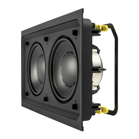
BMB CSX-550(SE) User manual

SPEAKER SYSTEM
CSX-550(SE)
Right speaker systemConnected amplifier
(Speaker terminals)
Left speaker system
LR
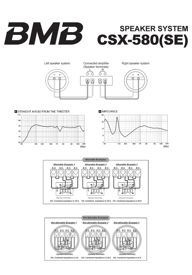
Allowable Examples
6 Ω
R L
R L
6 Ω 6 Ω 6 Ω 6 Ω6 Ω 8 Ω 8 Ω 8 Ω 8 Ω 8 Ω 8 Ω
Allowable Example 1 Allowable Example 2 Allowable Example 3
(Speaker terminals) (Speaker terminals) (Speaker terminals)
OK: Combined impedance is 12 Ω OK: Combined impedance is 14 Ω OK: Combined impedance is 16 Ω
R L
R L
R L
R L
Not-allowable Examples
Not-allowable Example 1 Not-allowable Example 2 Not-allowable Example 3
(Speaker terminals) (Speaker terminals) (Speaker terminals)
NG: Combined impedance is 3 Ω NG: Combined impedance is 3.4 Ω NG: Combined impedance is 4 Ω
6 Ω 6 Ω 6 Ω 6 Ω 6 Ω6 Ω 8 Ω 8 Ω 8 Ω 8 Ω 8 Ω 8 Ω
RL
RL
RL
RL
RL
RL

Tweeter for high pitch sound Squawkers for midrange/high tone Tweeter for high pitch sound
Left speaker Right speaker
Woofers for deep bass
Standard speaker layout
The
squawker
unit
Remove these
four screws.
Safety catch for lock
Left speaker
Safety catch for lock
Pull the duct
hole with
a hand.
Squawker:
Installed to
point a bit
inward.
Factory set status
Left speaker
Rotate the squawker
180 degrees so
that they are installed
to point outward.
Secure the screws firmly.
Duct hole
Right speaker
Squawker Squawker
Duct hole
Secure the screws firmly.

OWNER’S MANUAL THANK YOU VERY MUCH FOR PURCHASING THIS
BMB SPEAKERS SYSTEM. BEFORE USE, PLEASE
READ FOLLOWING INSTRUCTIONS THROUGH
CAREFULLY AND FAMILIARIZE YOURSELF WITH
THE OPERATION OF THE SYSTEM.
BEFORE USE
Operating Precautions
The maximum input power of these speakers is 400 W (at peak). Higher levels of input power may cause damage to the speaker system and so
take every precaution to keep the power down to the specification.
Even if an amplifier with a maximum output power of less than 400 W is employed, do not use the speakers with the volume turned up too high
or the sound distorted. This may damage the speakers.
Make sure that the amplifier’s power switch is at the OFF position when connecting the speakers to the amplifier.
Make sure that the amplifier’s volume control is turned down to its lowest setting when the amplifier’s power switch is set to the ON position.
CONNECTIONS
INSTALLATION
Make sure that you set the power switch on the amplifier to the OFF position when connecting the speakers to the amplifier.
Align the (–) and (+) polarities of the speakers with the (–) and (+) polarities of the left (L) and right (R) channels of amplifier, and connect the
speakers to the speaker terminals on the amplifier.
* If the polarities of the left and right speakers are not aligned properly, the quality of the reproduced sound, the ambience and the feeling of
direction will all be markedly impaired.
* When making the connections, take every precaution to prevent the speaker cords’ central cores from being shorted.
Installing the Speakers
Avoid installing the speakers in a location exposed to direct sunlight and high levels of humidity.
Avoid also locations in the vicinity of stoves and other sources of heat.
With a speaker system, the sound which is heard varies greatly according to the installation location. Bear in mind the following points in order to
derive the most enjoyment from music.
a) Install the speaker at the upper position than your ears level when you listen to the sound under normal listening conditions.
b) The best distance between the speakers is approx. 2 to 5 m.
c) The bass sounds fuller if the speakers are installed on a solid and stable stand of shelf, or if they are placed against a wall.
The bass sound will lose its impact if objects which do not reflect the bass well enough are placed in front of the speakers.
If you plan to hang your speakers from the ceiling, contact a professional installer.
Caution:
If you want to suspend the CSX-550 from the ceiling, use adequate mounting hardware that can bear the load. In addition, be sure to secure the
mounting hardware onto a place of high-tensile strength using screws appropriate to the ceiling materials.
MAINTENANCE OF CABINET
When the cabinets are dirty, clean off the dirt with a soft cloth. If the dirt is engrained, moisten a soft cloth in cold or lukewarm water, wring it out, and
then wipe off the dirt. Never use thinners or alcohol since these substances can impair the finish of the cabinet. Also, avoid using insecticide and
other sprays near the speakers.
The CSX-550 features a multi-speaker configuration based on the multidirectional method that is capable of delivering a dynamic sound widely even
in a spacious room. It comprises 3 speakers: a woofer located in the center of the cabinet responsible for deep bass, one squawker reproducing
mid/high frequencies, and one tweeter for high tones. The squawker and tweeter are installed in the cabinet with specific angles. In addition, the
squawker unit can be vectored to any direction to support various environment conditions.
They are set by factory default to the standard position so as to create a sound field all over the floor level in a big room.
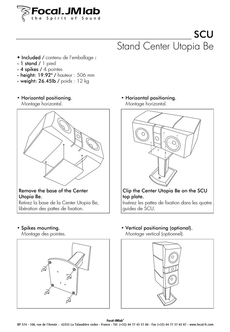
1. Pull the right and left speaker grills firmly to remove them. (Each speaker grill has a set of safety catches on the upper and lower ends, which are
locked to the cabinet. You can easily release the lock to remove the grill by pulling hard the duct hole with a hand.)
2. Use a Phillips-head screwdriver to remove the four screws that hold the squawker to the cabinet.
Caution:
Do not unscrew the four screws that hold the squawker to its black platform. In addition, make sure never to remove the tweeters located above
the squawker; the tweeters are identical in appearance to the squawker units. Note that you can not change the direction of the tweeters.
3. Rotate the squawker with its black platform 180 degrees clockwise or counterclockwise so that it points significantly outward, and then secure it
with the four screws. Make sure to secure at the same time a thin airtight gasket between the platform and the cabinet.
Caution:
Once you removed the screws, avoid pulling out, dropping or rotating more than 180 degrees the squawker unit, or the cable may be
disconnected from the unit.
4. Push the grills in place, pressing with a finger the safety lock catch located in the upper and lower ends of the grill in order that it may not
damage the cabinet.
Making Allowable Connections between Speakers and Your Amplifier (Ex. 4 Speakers)
Configure and wire the speakers so that the combined impedance falls within 6 to 32 Ω.
Note:
The specification allows the combined impedance ranging 4 to 32 Ω, however, 4 Ω configuration is not recommended; avoid it whenever possible.
If you want to expand the sound field all over a big room, in stead of focusing on the floor level...
ACCESSORIES
Owner’s manual: 1 pc
About Multidirectional Method Speakers
English

http://www.bmb.com
Type:
Speaker units:
Maximum input power:
Sound pressure level:
Frequency response:
Impedance:
Dimensions:
Mass:
3 Ways 3 Speakers
20 cm Woofer x 1
8 cm Cone Type Squawker x 1
8 cm Cone Type Tweeter x 1
High-performance oven cone
400 W
90 dB/W/m
45 - 20 kHz
8 Ω
464 (W) x 268 (H) x 257 (D) mm
9.0 kg
SPECIFICATIONS
Other BMB Speakers manuals
