BOB-CAT 912480 User manual

PARTS MANUAL
MAN 4171262
Rev. B 02-2015
912480
BC QUICKCAT FX651V KAW 48" SD
912520
BC QUICKCAT FX691V KAW 52" SD
912610
BC QUICKCAT FX731V KAW 61" SD
OPERATOR’S MANUAL 4171263 www.bobcatturf.com
MOWERS
®

CALIFORNIA
Proposition 65 Warning
Diesel engine exhaust and some
of its constituents are known to the
State of California to cause cancer,
birth defects and other reproductive
harm.
Californie Proposition 65 Avertisse-
ment
Les échappements des moteurs diesel et
certains de leurs composés sont recon-
nus par l’Etat de Californie pour être
cancérigènes, provoquer des défauts con-
génitaux etd’autresdangersenmatièrede
reproduction.
ADVERTENCIA
AVERTISSEMENT
WARNING
The engine exhaust from this product
containschemicals knowntotheState
of California to cause cancer, birth
defects or other reproductive harm.
California Advertencia
de la Proposicion 65
El estado de California hace saber
que los gases de escape de los mo-
tores diesel y algunos de sus com-
ponentes producen cáncer, defectos
de nacimiento y otros daños en el
proceso de reproducción humana.
L’
é
mission du moteur de ce mat
é
riel
contient des produits chimiques que
l’Etat de Californie consid
è
re
ê
tre
canc
é
rig
è
nes,provoquerdesd
é
fauts
cong
é
nitaux et d’autres dangers en
mati
è
re de reproduction.
El estado de California hace saber
que los gases de escape de este
producto contienen productos quÍmi-
cos que producen cáncer, defectos
de nacimiento y otros daños en el
proceso de reproducción humana.
CALIFORNIA
Proposition 65 Warning
Battery posts, terminals, wiring
insulation, and related accessories
contain lead and lead compounds,
chemicals known to the State of
California to cause cancer and birth
defects or other reproductive harm.
WASH HANDS AFTER HANDLING.

1
QUICKCAT
MOWERS
®
IMPORTANT MESSAGE
Thank you for purchasing this Schiller Grounds Care, Inc. product. You have purchased a world class mowing product, one of the best
designed and built anywhere.
This machine comes with an Operation and Safety Manual and a separate Setup, Parts and Maintenance Manual. The useful life and good
service you receive from this machine depends to a large extent on how well you read and understand these manuals. Treat your machine
properly, lubricate and adjust it as instructed, and it will give you many years of reliable service.
Your safe use of this Schiller Grounds Care, Inc. product is one of our prime design objectives. Many safety features are built in, but we
also rely on your good sense and care to achieve accident-free operation. For best protection, study the manuals thoroughly. Learn the
proper operation of all controls. Observe all safety precautions. Follow all instructions and warnings completely. Do not remove or defeat
any safety features. Make sure those who operate this machine are as well informed and careful in its use as you are.
See a Schiller Grounds Care, Inc. dealer for any service or parts needed. Schiller Grounds Care, Inc. service ensures that you continue to
receive the best results possible from Schiller Grounds Care, Inc. products. You can trust Schiller Grounds Care, Inc. replacement parts
because they are manufactured with the same high precision and quality as the original parts.
Schiller Grounds Care, Inc. designs and builds its equipment to serve many years in a safe and productive manner. For longest life, use this
machine only as directed in the manuals, keep it in good repair and follow safety warnings and instructions. You’ll always be glad you did.
Schiller Grounds Care, Inc.
One Bob Cat Lane
Johnson Creek, WI 53038-0469
02-2015
TABLE OF CONTENTS..................................................................... FIGURES..........................................................PAGE
SAFETY................................................................................................................................................................................2
ASSEMBLY AND SETUP..................................................................................................................................................3-4
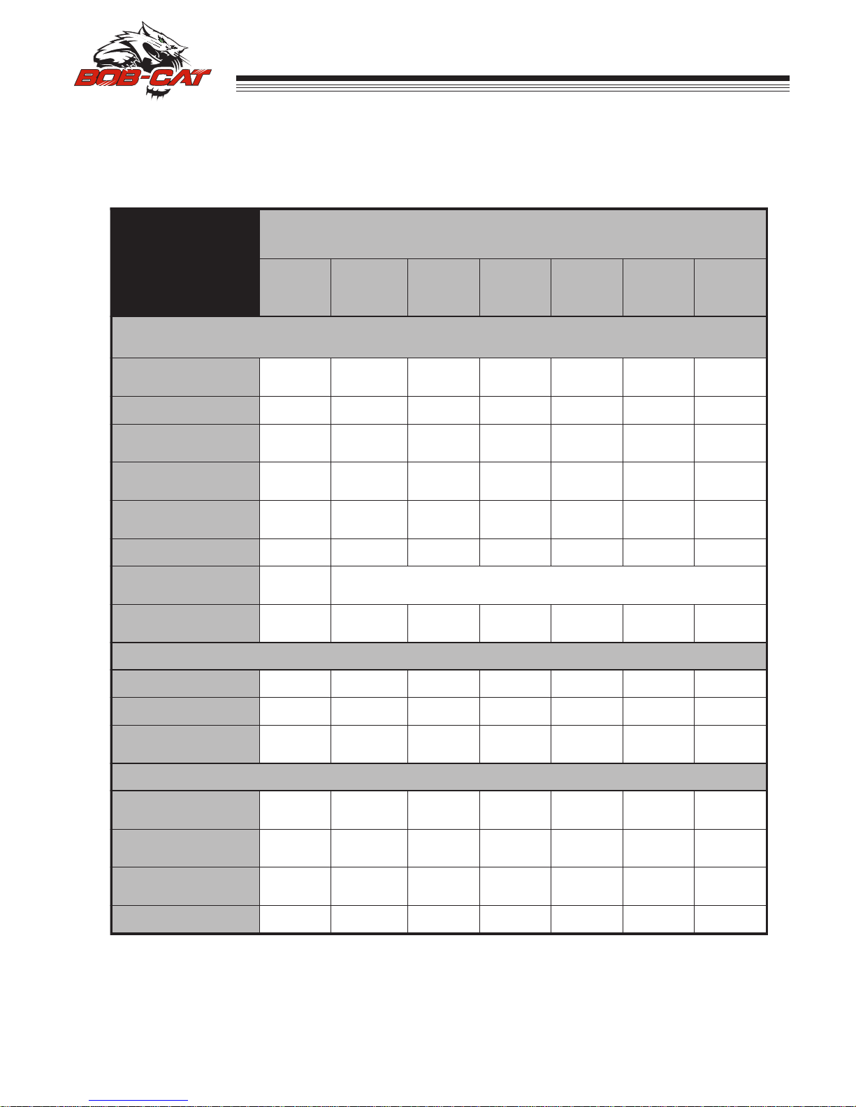
MAINTENANCE CHART .....................................................................................................................................................5
MAINTENANCE RECORD...................................................................................................................................................6
MAINTENANCE .............................................................................................................................................................7-13
ADJUSTMENTS............................................................................................................................................................14-17
BELT REPLACEMENT ......................................................................................................................................................18
SPECIFICATIONS.........................................................................................................................................................19-20
PARTS SECTION...............................................................................................................................................................21
ENGINE DECK ASSEMBLY............................................................FIGURE 1.......................................................... 22, 23
RIDER PLATFORM ASSEMBLY.....................................................FIGURE 2............................................................ 24, 25
WHEEL & TRANSAXLE ASSEMBLY..............................................FIGURE 3............................................................26, 27
FUEL TANK & BATTERYASSEMBLY.............................................FIGURE 4............................................................28, 29
PARKING BRAKE ASSEMBLY........................................................FIGURE 5............................................................ 30, 31
UPPER WIRE HARNESS ...............................................................FIGURE 6............................................................ 32, 33
LOWER WIRE HARNESS...............................................................FIGURE 7............................................................34, 35
TOWER ASSEMBLY ......................................................................FIGURE 8............................................................36, 37
CONTROLS ASSEMBLY.................................................................FIGURE 9............................................................38, 39
DECK LIFTASSEMBLY ..................................................................FIGURE 10..........................................................40, 41
CASTER & BELT COVER ASSEMBLY...........................................FIGURE 11..........................................................42, 43
48" SIDE DECK ASSEMBLY...........................................................FIGURE 12.......................................................... 44, 45
52" SIDE DECK ASSEMBLY...........................................................FIGURE 13.......................................................... 46, 47
61" SIDE DECK ASSEMBLY...........................................................FIGURE 14.......................................................... 48, 49
CHUTE, BAFFLES, & EDGES ASSEMBLY....................................FIGURE 14..........................................................50, 51

2
QUICKCAT
MOWERS
®
SAFETY
NOTICE !!!
Unauthorized modications may present extreme
safety hazards to operators and bystanders and
could also result in product damage.
Schiller Grounds Care, Inc. strongly warns against,
rejects and disclaims any modications, add-on
accessories or product alterations that are not
designed,developed,testedandapprovedbySchiller
Grounds Care, Inc.Engineering Department. Any
Schiller Grounds Care, Inc.product that is altered,
modied or changed in any manner not specically
authorized after original manufacture-including the
additionof“after-market”accessoriesorcomponent
parts not specically approved by Schiller Grounds
Care, Inc.-will result in the Schiller Grounds Care,
Inc.Warranty being voided.
Any and all liability for personal injury and/or
property damage caused by any unauthorized
modications, add-on accessories or products not
approved by Schiller Grounds Care, Inc.will be
considered the responsibility of the individual(s) or
company designing and/or making such changes.
Schiller Grounds Care, Inc.will vigorously pursue
full indemnification and costs from any party
responsibleforsuchunauthorizedpost-manufacture
modications and/or accessories should personal
injury and/or property damage result.
This symbol means:
ATTENTION!
BECOME ALERT!
Your safety and the safety of others is involved.
Signal word denitions:
The signal words below are used to identify levels
of hazard seriousness. These words appear in this
manualandonthesafetylabelsattachedtoSchiller
Grounds Care, Inc.machines. For your safety and
thesafetyofothers,readandfollowtheinformation
given with these signal words and/or the symbol
shown above.
DANGER indicates an imminently hazardous
situationwhich, if notavoided, WILL result in death
or serious injury.
WARNING indicates a potentially hazardous
situation which, if not avoided, COULD result in
death or serious injury.
CAUTIONindicatesapotentiallyhazardoussituation
which,ifnotavoided,MAY resultinminorormoderate
injury. It may also be used to alert against unsafe
practices or property damage.
CAUTION used without the safety alert symbol
indicates a potentially hazardous situation which, if
not avoided, MAY result in property damage
MODEL NUMBER: This number appears on
sales literature, technical manuals and price lists.
SERIAL NUMBER: This number appears only
on your mower. It contains the model number
followed consecutively by the serial number.
Use this number when ordering parts or seeking
warranty information. Located behind rider pad
on frame of unit.

3
QUICKCAT
MOWERS
®ASSEMBLY AND SETUP
TOOLS REQUIRED FOR ASSEMBLY
- Wrecking bar
- Claw hammer
- Ratchets: 3/8”,e
- Sockets: 9/16”, 3/4"
- Wrenches: 3/8", 9/16", 3/4"
- Straight edge
- Tire pressure gauge
- Blocks (for deck leveling)
NOTE: All references below to the “right” or “left” are with respect to an operator at the controls.
1. UNCRATE UNIT
Discard packing materials. Remove and discard shipping brackets. Tighten caster wheel axle bolts
against caster axle spanner bushings.
2. Set rear tire pressures to 12 lbs/in2(0.8 kg/cm2). Tires are overinated for shipping. Front tires should be
15 lbs/in2(1.05kg/cm²).
DECK LEVELING
1. Park the machine on a smooth, level surface.
Raise the deck to the transport position.
2. Lower the deck onto a set of equal height blocks
Aunder the rear corners of the deck. Place
another set of blocks under the front of the deck
so that the deck top is pitched forward 1/8".
NOTE: The front and rear of the deck are at different
heights.
3. Measure the height of the blade cutting edge
above the ground. Remove pin Band set the
height of cut lever Eto that height
4. Loosen nuts on bolts G. Move bolts in slot to
remove slack in chain. Tighten nuts on bolts G.
A 1/8" forward pitched deck provides the best horsepower.
A level deck provides the best quality of cut.
A 1/8" rearward pitched deck provides the best striping.
Certain grass types and conditions may vary.

4
QUICKCAT
MOWERS
®
5. FINAL PREPARATIONS
- Check the engine and hydraulic oil levels. Top up with the correct oil if necessary. Use SAE 10W30 mo-
tor oil for the engine. Use fresh, clean SAE 20W50 motor oil for the hydraulic system. After running for
one hour, let hydraulic system oil cool. When cold, check levels.
Battery acid is caustic and fumes are explosive and can cause serious injury or death.
Use insulated tools, wear protective glasses or goggles and protective clothing when working with batteries.
Read and obey the battery manufacturer’s instructions.
Be certain the ignition switch is OFF and the key has been removed before servicing the battery.
a) Verify battery polarity before connecting or disconnecting the battery cables.
b) When installing the battery, always assemble the RED, positive ( + ) battery cable rst and the
ground, BLACK, negative ( - ) cable last.
c) Tighten cables securely to battery terminals and apply a light coat of silicone dielectric grease to
terminals and cable ends to prevent corrosion. Keep terminal covers in place.
- Read Operation and Safety Manual before starting.
- Deck can be adjusted to allow for the best horsepower, best quality of cut, or best striping. See deck
leveling procedure in the Adjustments Section in this manual to set as desired.
- Run engine at full RPM for 5 minutes before engaging blades to allow the engine to be fully lubricated
before load is applied.
- Check the hydrostat neutral adjustment. Neutral is set at the factory but may require readjustment if
air trapped during the initial oil ll has worked out of the system. See Adjustments Section later in this
manual.
- Do not use the machine without an approved grass collector, the grass discharge chute or mulching
plates correctly tted.
ASSEMBLY AND SETUP

5
QUICKCAT
MOWERS
®MAINTENANCE CHART
ECNANETNIAM NOITAREPO
neewtebsemitmumixameraslavretniesehT.bojgniognonasiecnanetniaM .snoitidnocerevesrednunetfoerommrofreP.snoitarepoecnanetniam
5TSRIFSRUOH
EROFEB HCAE ESU
YREVE 52 SRUOH
YREVE 05 SRUOH
YREVE 001 SRUOH
YREVE 002 SRUOH YLRAEY
ENIGNE
snoitcurtsnidnanoitamrofnilanoitiddaroflaunamenigneehttlusnoC
pUpoT/kcehC leveLliO X
skaeLroFkcehCX
ekatnIriAnaelC neercS X
renaelCriAnaelC renaelcerP X
renaelCriAnaelC tnemelE X
sniFgnilooCnaelC X
dnAliOegnahC retliF alunams'rerutcafunamenigneeeS
ecalpeR/kcehC sgulPkrapS X
ELXASNART
leveLliOkcehCX
skaeLroFkcehCX
dnAliOegnahC retliF X
ENIHCAM
kcolretnIkcehC noitarepO X
eriTkcehC serusserP X
pUpoT/kcehC yrettaB X
stnioPllAetacirbu
X
LX
X
X

6
QUICKCAT
MOWERS
®
NOTES
________________________________________________
________________________________________________
________________________________________________
________________________________________________
________________________________________________
________________________________________________
________________________________________________
________________________________________________
________________________________________________
________________________________________________
________________________________________________
MAINTENANCE RECORD
LARENEG
ETAD SRH ETAD SRH ETAD SRH ETAD SRH ETAD SRH ETAD SRH
serusserPeriTkcehC
stnioPllAetacirbuL
stloB&stuNkcehC
ENIGNE
leveLliOkcehC
liOegnahC
naelC tnemelErenaelCriA
sniFgnilooCnaelC
ecalpeR tnemelErenaelCriA
paG&naelC sgulPkrapS
ELXASNART
retliFdnAliOegnahC
.retlifdnalioenigneegnahcnoitarepofosruoh5tsrifretfA:ETON

7
QUICKCAT
MOWERS
®MAINTENANCE
CHECK DAILY
Operator Presence Interlock System - Start Operation
For the engine to crank, the parking brake must be ON, the PTO (blades) OFF. Stand on the operator plat-
form and check, one by one, if the engine will crank with the parking brake OFF or the PTO (Blades) ON.
Operator Presence Interlock System - Run Operation
In order for the engine to run, the operator must either be standing on the platform, or walking behind the unit
with the platform up, the parking brake in the OFF position and the LH control handle held down out of the
neutral position.
The engine may also run if the parking brake is in the ON position, the LH control handle is in the NEUTRAL
position rotated up, and the PTO (blades) are OFF.
To check:
1. Start the engine and run at 1/2 throttle.
2. With the LH control handle in the NEUTRAL position rotated up, move the parking brake lever to OFF
and turn the PTO (Blades) ON. Each check should kill the engine after 1/2 second delay. ( A 1/2 second
delay is built into the system to prevent engine cut-out when traversing rough terrain.)
Repair machine before using if the Operator Presence Interlock System does not operate correctly in start or
run. Contact your authorized BOB-CAT dealer.
Hardware
Tighten any nuts and bolts found loose. Replace any broken or missing cotter pins. Repair any other
problems before operating.
Tire pressure
Rear Tires should be kept inated at 12 lbs/in2(.84kg/cm2). Improper tire ination can cause rapid tire wear
and poor traction. Uneven ination can cause uneven cutting. Front tires should be 15p.s.i. (1.05 kg/cm²)
BATTERY-AGM TYPE BATTERY SUPPLIED
Battery acid is caustic and fumes
are explosive and can cause serious injury or death.
Use insulated tools, wear protective glasses or
goggles and protective clothing when working with
batteries. Read and obey the battery manufacturer’s
instructions.
Be certain the ignition switch is OFF and the key has
been removed before servicing the battery.
1. Verify battery polarity before connecting or discon-
necting the battery cables.
2. When installing the battery, always assemble
the RED, positive ( + ) battery cable rst and the
ground, BLACK, negative ( - ) cable last.
3. When removing the battery, always remove the
ground, negative ( - ) cable rst and the red, positive
( + ) cable last.
4. AGM type battery. Use AGM charger when
charging. P/N 4171973
5. Clean the cable ends and battery posts with steel
wool. Use a solution of baking soda and water
to clean the battery. Do not allow the solution to
enter into the battery cells.
6. Tighten cables securely to battery terminals and
apply a light coat of silicone dielectric grease to
terminals and cable ends to prevent corrosion.
Keep terminal covers in place.

8
QUICKCAT
MOWERS
®
LUBRICATION
Every 50 hours of operation, lubricate the following points (1-3) with grease:
1. Deck lift pivots (4 points)
2. Pull arm pivots (4 points)
3. Deck idler pivot (1 point)
Every 500 hours or once a year:
4. Caster wheel pivots (2 points)
NOTE ON BLADE SPINDLES -The blade spindles on these machines use a superior sealed bearing that
does not require re-lubrication.
MAINTENANCE
11
2
3
4

9
QUICKCAT
MOWERS
®MAINTENANCE
ENGINE OIL
Do not perform engine maintenance without the
engine off, spark plug wires disconnected and PTO
disengaged.
AFTER FIRST FIVE (5) HOURS
While the engine is warm:
1. Release the oil drain hose assembly from the
engine clip J. Lay hose assembly over the frame
edge.
2. Remove the rubber cap Dfrom the tip of the
hose assembly and turn the drain valve to allow
oil to drain from the engine. Dispose of used oil
in accordance with local requirements.
3. Clean drain valve and tighten the plastic portion
of the drain valve back into the metal portion of
the valve. Replace rubber cap over the tip of the
valve. Replace hose assembly back into engine
clip.
4. Change oil lter.
5. Fill the crankcase with fresh oil to the full mark.
Do not overll. See engine manual for oil
specications.
DAILY
1. Check oil level with the dipstick.
2. If oil is needed, add fresh oil of proper
viscosity and grade. See engine manual for oil
specications. Do not overll.
3. Replace dipstick before starting engine.
PERIODIC OIL CHANGES
1. See engine manual for oil and lter change inter-
vals after the break-in period.
2. Follow instructions for rst oil change, above.
SPARK PLUGS
Remove each plug and check condition.
– Good operating conditions are indicated if the plug has a light coating of grey or tan deposit.
– A white blistered coating indicates overheating. A black coating indicates an “over rich” fuel mixture. Both
may be caused by a clogged air cleaner or improper carburetor adjustment.
– Do not sandblast, wire brush or otherwise attempt to repair a plug in poor condition. Best results are
obtained with a new plug.
– Set plug gap as specied in engine manual.
FUEL FILTER
An in line fuel lter is located in the fuel supply line. Inspect at every oil change to make sure it is clean and
unobstructed. Replace if dirty.

10
QUICKCAT
MOWERS
®
MAINTENANCE
TRANSAXLES
Inattention to proper safety, operation, or
maintenance procedures could result in personal
injury, or damage to the equipment. Schiller
Grounds Care, Inc. recommends returning the
machine to your authorized Schiller Grounds
Care, Inc. dealer for service or repair.
Perform transaxle maintenance with the engine off,
spark plug wires disconnected and PTO disengaged.
TRANSAXLE FLUID CHANGE
Change the transaxle uid every 200 hours of
operation. It is essential that the exterior of the
transaxle be free of debris, prior to uid maintenance.
1. Remove the three 1/4" lter guard screws and
lter guard A. Remove the oil lter Bfrom the
transaxle and discard. Dispose of used oil in ac-
cordance with local requirements.
2. Wipe the lter base surface off and apply a lm
of new oil to the gasket of the new replacement
lter. Install the new lter by hand, turn 3/4 to
one full turn after the lter gasket contacts the
lter base surface.
3. Re-install the lter guard and torque the three
screws to 65 in. lbs. each.
4. Remove cap C, ll the transaxles through the
expansion tank Dwith approximately 2 quarts of
SAE 20W-50 engine oil PER TRANSAXLE.
Do not overll! If you overll the transaxle while the unit
is "cold", it may overow as it reaches normal operating
temperatures. The oil level should not be above the
manufacturer's suggestions. The oil level should be lled
to the full cold line on the overow tank. This will allow
the space needed for the oil to expand as it warms up.
5. After starting engine, check the uid level and
continue to add oil to overow tank D to ll line
on tank.
6. Purge the transaxles, following the purging pro-
cedures.

11
QUICKCAT
MOWERS
®
PURGING TRANSAXLES
Due to the effects air has on efciency in hydrostatic
drive applications, it is critical that it be purged from
the system.
These purge procedures should be implemented any
time a hydrostatic system has been opened to fa-
cilitate maintenance or any additional uid has been
added to the system.
Purging may be required if the unit shows any of the
following symptoms:
- Noisy operation.
- Lack of power or drive after short term use.
- High operation temperature, excessive oil
expansion.
1. Check the transaxle uid, ll to proper level, if
required. Should be to the Full Cold Line.
2. Raise the drive wheels off the ground. Support
unit with jack stands or other suitable means.
3. Open bypass valves. To open the bypass valves,
move the parking brake to any OFF position,
then lift and pull bypass control rod Cthrough the
large opening D, until the control rod stop is past
the opening. Drop rod Cinto the small opening
to lock in place. Repeat for the other bypass
control rod. Start engine, slowly move the control
levers in both forward and reverse directions 5
to 6 times. As air is purged from the unit, the oil
level will drop.
4. With the bypass valve closed, and the engine
running, slowly move the control levers in both
forward and reverse directions 5 to 6 times.
5. Stop engine. Check the transaxle uid level, add
uid as required.
6. It may be necessary to repeat steps 3-5 until all
the air is completely purged from the system.
When the transaxle moves forward and reverse
at normal speed, purging is complete.
MAINTENANCE
ENGINE COOLING
Continued operation with a clogged cooling system
will cause severe overheating and can result in en-
gine damage.
- Daily: Clean air intake screen Son air cooled
engines.
- Every 100 hours: Clean cooling ns beneath
blower housing Hwith reference to information in
the engine manufacturer's manual.
HEAVY DUTY CYCLONIC AIR CLEANER
Clean and replace the air cleaner element as
specied in the service chart. Uneven running, lack
of power or black exhaust fumes may indicate a dirty
air cleaner.
To replace air cleaner elements:
1. Unclamp end cover X and remove existing
cleaner elements.
2. Insert new elements Y and Zand replace cover.
Ensure the breathing port Ais pointing down and
towards the front of the tractor.

12
QUICKCAT
MOWERS
®
MAINTENANCE
CLEANING MACHINE
Clean the machine after use. Compressed air is
recommended. Do not use a pressure washer. The
machine will run cooler and last longer if kept free of
clippings and other debris. A clean machine also re-
duces the risk of re due to accumulation of combus-
tible debris and chaff.
Brush or blow clippings and debris off the cutterdeck
and engine deck. Clippings and debris should be
kept from accumulating around the exhaust system
and under the exhaust guards. This can be doen
by using compressed air. DO NOT use a pressure
washer.
WASHING MACHINE
CAUTION: Improperly washing a machine can cause
water to enter bearings and other components. This
can greatly reduce component life.
– Do not use a pressure washer. Do not direct
water at bearings or seals. High pressure water
can blow past seals and enter sealed bearings.
– Allow the machine to cool down before washing.
Water on a warm machine can be sucked into
sealed bearings as they cool.
– Avoid getting electrical connections wet. Water
can cause electrical faults and corrosion of elec-
trical components.
SPECIFIC TORQUES
BLADE BOLTS 70 FT-LBS (95 Nm)
WHEEL LUG NUTS 75-100 FT-LBS (102-135.5 Nm)
CLUTCH MOUNTING BOLT 50 FT-LBS (68 Nm)
TRANSAXLE PULLY BOLT 28.3-41.5 FT-LBS (38-56 Nm)
TRANSAXLE DRAIN PLUG 15-20 FT-LBS (20-27 Nm)
TRANSAXLE FILTER 100-150 IN-LBS (14.6-16.9 Nm)

13
QUICKCAT
MOWERS
®
MAINTENANCE
BLADE REMOVAL
Follow these instructions to prevent injury during
blade removal:
1. Loosen with a box wrench or a socket and long
breaker bar. To gain additional leverage, slip a
long pipe or thick-walled tube over breaker bar or
wrench.
2. Insert wood block Aas shown, with grain
perpendicular to blade, to prevent blade from
turning when loosening.
3. Wear thickly padded gloves. Keep hands clear
of blade path. Blades may rotate when bolt
releases.
SHARPENING
Blades may be sharpened by ling or grinding.
- Inspect blades before sharpening.
- Replace bent or cracked blades.
- Replace blades when the lift portion has worn
thin.
-Maintain cut angle at 30o.
-Do not overheat blades when sharpening.
- Always use BOB-CAT blades. Use of another
manufacturer’s blades may be dangerous.
BLADE BALANCE
Blade balance must be maintained at 5/8 oz-in
(19.4 g-cm) or less. Failure to keep blades balanced
causes excess vibration, wear, and shortened life of
most components of the machine.
To balance a blade:
1. Sharpen blade rst.
2. Balance the blade at the center.
3. Attach a 1/8 oz (3.9 g) weight at a distance 5”
(127 mm) from center on the light end. This
should make the light end the heavy end:
- If it does, the blade is balanced.
- If does not, le or grind the heavy end until
the addition of the weight makes the light end
the heavy end.
BLADE INSTALLATION
1. Wear thickly padded gloves to prevent cuts from
the sharp blade.
2. Insert the blade bolt, in order, through the conical
washer (cup side toward the blade, as shown),
the blade, and the blade spacer.
3. Install assembly on the blade spindle.
4. Torque the blade bolt to 70 ft-lbs.

14
QUICKCAT
MOWERS
®
BELTS
All belts are tensioned by spring loaded idlers. No adjustment is required.
ADJUSTMENTS
DECK LEVELING
1. Park the machine on a smooth, level surface.
Raise the deck to the transport position.
2. Lower the deck onto a set of equal height blocks
Aunder the rear corners of the deck. Place
another set of blocks under the front of the deck
so that the deck top is pitched forward 1/8".
NOTE: The front and rear of the deck are at different
heights.
3. Measure the height of the blade cutting edge
above the ground. Remove pin Band set the
height of cut lever Eto that height
4. Loosen nuts on bolts G. Move bolts in slot to
remove slack in chain. Tighten nuts on bolts G.
A 1/8" forward pitched deck provides the best horsepower.
A level deck provides the best quality of cut.
A 1/8" rearward pitched deck provides the best striping.
Certain grass types and conditions may vary.
HEIGHT OF CUT
The height of cut is set by moving height of cut pin B
to the hole designated for the height of cut desired.
To change the height of cut:
1. Lift the deck to the highest position using the lift
handle E.
2. Move pin Bto the selected hole.
3. Lower the deck until the lift handle Eis stopped
by the pin.
NOTES:
– Height of cut may vary due to the amount of
tread on the tires, tire diameter or ination pres-
sure.
– For best results, adjust the deck rollers for the
height of cut to be used (see below).

15
QUICKCAT
MOWERS
®ADJUSTMENTS
DECK ROLLERS
The rear outside deck rollers are adjustable up and
down to provide improved deck otation and scalp-
ing protection at various heights of cut. They are not
intended to ride continuously on the ground. Adjust
no closer than 3/8” (10mm) to the ground.
Height of cut ranges for roller adjustment
FRONT DECK LIP
Adjustable front deck lips have been provided on
48in. 52 in. and 61" cutterdecks for various grass
types and cutting conditions.
To revise per conditions:
1. Loosen the front bolts S.
2. Adjust height of H.
3. Retighten Sonce you have desired height.
Suggested heights for grass types:
(Factory setting is all the way down.)
-Southern season grasses generally will work with
the lip down. When cutting Bahia grass or other
grasses where seed pods grow higher then the
actual grass blade, you will want to adjust the lip all
the way up.
-Northern season grasses generally require the lip
all of the way down.

16
QUICKCAT
MOWERS
®
ADJUSTMENTS
PARKING BRAKE
NOTE: There are 2 brakes, 1 on each transaxle.
The parking brake should keep the machine from
moving. To check the parking brake, park the ma-
chine on a level surface, open the bypass valves
(See purging transaxles scection for instruction) and
set the parking brake to ON. Attempt to move the
machine forward and backward by pushing it. If the
machine moves, adjust the parking brake linkage as
follows:
1. Move the machine to a at horizontal surface.
2. Move the parking brake handle to the OFF posi-
tion.
3. Insure that the brake links Kare rotated toward
the rear of the machine. If not, remove cotter pin
Pfrom each brake link Kand brake rod R. Slide
brake rod Rout of each brake link K. Reinsert
rod Rinto each link Kand secure with cotter pin
P.
4. Tighten brake nut Nas needed. The length of
the threads protruding past the nut should mea-
sure 1/8" - 1/4".
5. Retest to insure the machine does not move.

17
QUICKCAT
MOWERS
®ADJUSTMENTS
HYDROSTAT TRANSAXLE
Aturnbuckle-style hydrostat neutral adjustment is
provided.
Neutral adjustment is for setting the location of the
control handles with respect to each other or the
operator presence slot, or parking brake locks.
Neutral: (neutral is set by the hydrostatic transaxles)
1. Loosen jam nuts A at both ends of the control rod
B.
2. Loosen the nuts C on the control lock rod D.
3. Rotate the control rod B until both left and right
handle is aligned with the slot on the control
panel.
4. Start the engine and run at low speed.
5. Tighten the jam nuts A at the top and the bottom
of the control rod B.
6. Press the control lock rod D into the slot in the
control and tighten nut C.
To check:
1. Start the engine and run at 1/2 throttle.
2. With the LH control handle in the NEUTRAL po-
sition rotated up, move the parking brake lever
to PARK and turn the PTO (Blades) ON. Each
check should kill the engine after 1/2 second de-
lay. ( A 1/2 second delay is built inot the system
to prevent engine cut-out when traversing rough
terrain.)
Repair machine before using if the Operator Pres-
ence Interlock System does not operate correctly
in start or run. Contact your authorized BOB-CAT
dealer.

18
QUICKCAT
MOWERS
®
BELT REPLACEMENT
Note: Always use Schiller Grounds Care, Inc.replacement belts, not general purpose
belts. Schiller Grounds Care, Inc. belts are specially designed for use on commercial
mowers and will normally last longer.
CUTTERDECK BELT
1. Remove center, left and right belt guards.
2. Set the cutterdeck in a middle height-of-cut posi-
tion.
3. Loosen bolt on belt guide so belt guide can be
moved to remove the belt.
4. Insert 3/8" ratchet extension in hole A on the
idler arm to back tensioning idler off to remove
belt from idler. Remove belt from cutterdeck
pulleys.
5. Remove belt from clutch pulley.
6. Install the new belt by performing these steps in
reverse order.
7. Cutterdeck spring will require tension adjustment
after belt installation. Adjust eyebolt so the dis-
tance between the inside of the eyebolt and the
inside of the hook is 6-3/4 ± 1/8".
TRANSAXLE DRIVE BELT
1. Remove engine-cutterdeck belt. (See cutterdeck
belt above)
2. To remove transaxle drive belt, use a 3/8" ratchet
and extension. Insert ratchet extension in the
square hole A of the transaxle idler arm. Rotate
enough to remove the transaxle drive belt.
3. Install a new transaxle drive belt by performing
these steps in reverse order.
NOTE: Inspect the fans. Replace if worn or
damaged.
5. Reinstall cutterdeck belt and guards.
NOTE: After usage of the machine, the belt will seat
into the pulleys and reduce the length of the
spring. DO NOT READJUST THE EYEBOLT.
This is normal. If you do adjust the eyebolt, you
will over tension the belt, greatly reducing the
belt's life.
This manual suits for next models
2
Table of contents
Other BOB-CAT Lawn Mower manuals
Popular Lawn Mower manuals by other brands

Scag Power Equipment
Scag Power Equipment SCR Operator's manual

Sabo
Sabo JS63 VARIO Operator's manual

Bosch
Bosch INDEGO 350 installation guide

Toro
Toro Recycler 20961 Operator's manual

Hornbach
Hornbach FQ-ARM 4038 BASIC Original instructions

Maschio
Maschio PALMA 720 Instruction manual for use and maintenance