BOLEX H 16 EBM Electric User manual

1
H16
EBM
ELECTRIC
Instructions
manual
I

O)
Oi
EBM
ELECTRIC
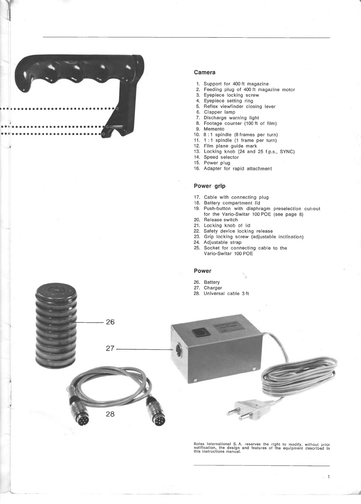
Camera
1.
Support
for
400
ft
magazine
2.
Feeding
piug
of
400
ft
magazine
motor
3.
Eyepiece
iocking
screw
4.
Eyepiece
setting
ring
5.
Reflex
viewfinder
closing
lever
6.
Clapper
lamp
7.
Discharge
warning
light
8.
Footage
counter
(100
ft
of
film)
9.
Memento
10.
8:1
spindle
(8
frames
per
turn)
11.
1:1
spindle
(1
frame
per
turn)
12.
Film
plane
guide
mark
13.
Locking
knob
(24
and
25
f.p.s.,
SYNC)
14.
Speed
selector
15.
Power
plug
16.
Adapter
for
rapid
attachment
Power
grip
17.
Cable
with
connecting
plug
18.
Battery
compartment
lid
19.
Push-button
with
diaphragm
preselection
cut-out
for
the
Vario-Switar
100
POE
(see
page
8)
20.
Release
switch
21.
Locking
knob
of
lid
22.
Safety
device
locking
release
23.
Grip
locking
screw
(adjustable
inclination)
24.
Adjustable
strap
25.
Socket
for
connecting
cable
to
the
Vario-Switar
100
POE
Power
26.
Battery
27.
Charger
28.
Universal
cable
3
ft
Bolex
International
S.
A.
reserves
the
right
to
modify,
without
prior
notification,
the
design
and
features
of
the
equipment
described
in
this
instructions
manual.
1
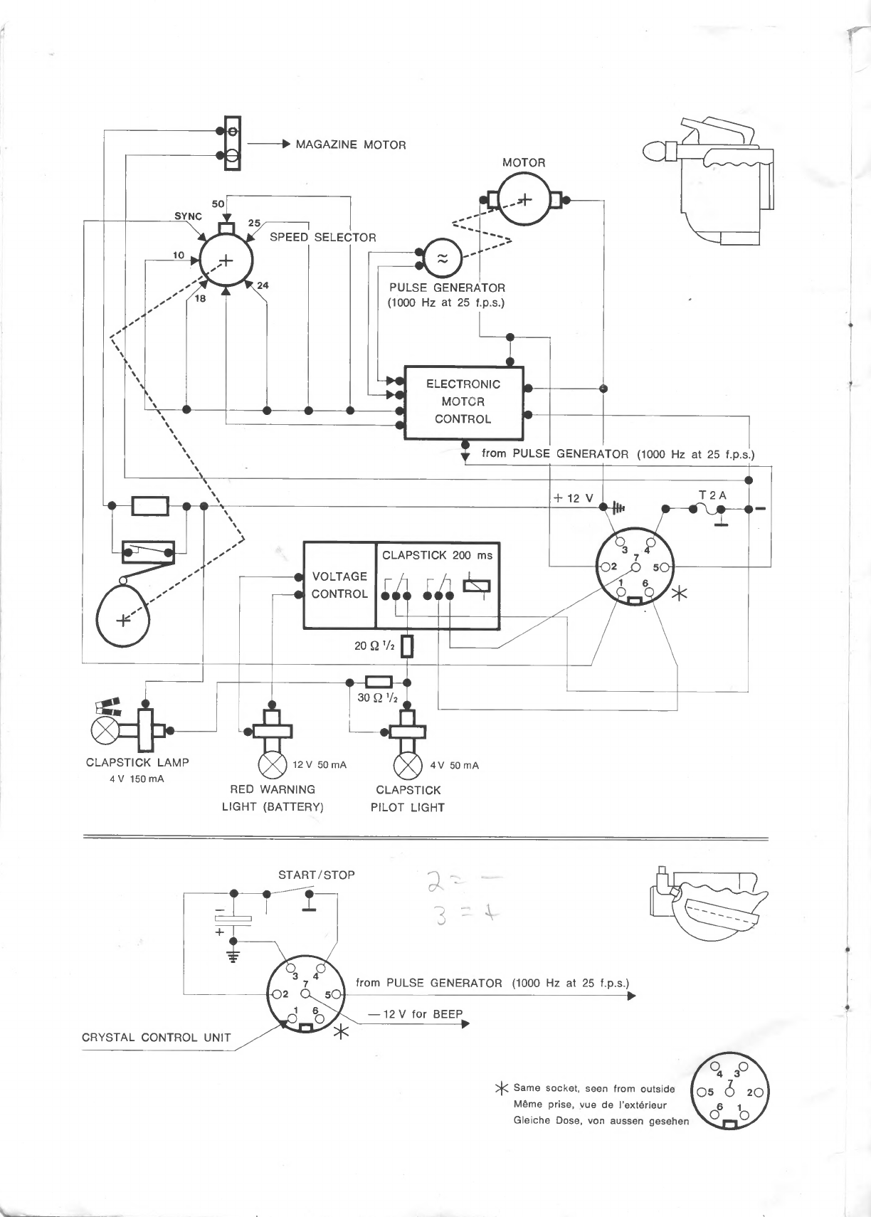
Ill
MAGAZINE
MOTOR
MOTOR
SPEED
SELECTOR
PULSE
GENERATOR
(1000
Hz
at
25
f.p.s.)
ELECTRONIC
MOTOR
CONTROL
from
PULSE
GENERATOR
(1000
Hz
at
25
f.p.s.)
VOLTAGE
CONTROL
CLAPSTICK
200
ms
Wi
^
A
j
30Q
V2
1
!
□
*_
^r~\
JlL
CLAPSTICK
LAMP
12
V
50
mA
QxQ
4
V
50
mA
4V
150
mA
RED
WARNING
CLAPSTICK
LIGHT
(BATTERY)
PILOT
LIGHT
START/STOP
;i--'
■
3
-v
^
7
\
from
PULSE
GENERATOR
(1000
Hz
at
25
f.p.s.)
)2
Cl
50j-C-^
.
rl
—12
V
for
BEEP
CRYSTAL
CONTROL
UNIT
>j<
Same
socket,
seen
from
outside
Meme
prise,
yue
de
I'exterieur
Gieiche
Dose,
von
aussen
gesehen

General
The
H
16
EBM
Electric
camera
is
particularly
well
suited
to
meet
the
requirements
of
professional
cameramen,
who
will
appreciate
the
following
advantages
:
electronically
stabilised
speeds
possibility
of
adapting
a
400
ft
magazine
possibility
of
synchronisation
by
crystal
control
unit
accessory
sync
pulse
equipment
a
remarkable
quality
and
fiability.
The
H16
EBM
Electric
camera
takes
100
ft
16
mm
film
spools
with
single
or
double
rows
of
perforations,
up
to
400
ft
spools
with
the
400
ft
magazine
accessory.
Films
with
a
single
row
of
perforations
are
used
when
a
magnetic
track
is
to
be
added
to
the
original
film.
At
each
extremity
of
the
film
there
is
a
leader
—
approxi¬
mately
Oft
at
the
beginning
and
3ft
at
the
end
—
to
prevent
the
sensitive
film
being
exposed
to
light
during
loading
or
unloading.
These
leaders
are
usually
removed
by
the
processing
laboratories.
We
advise
against
using
film
already
fitted
with
a
magnetic
stripe.
In
fact,
as
the
ferrous
oxide
layer
Is
less
smooth
than
the
stripe
fitted
after
developing,
the
magnetic
layer
can
cause
premature
wear
on
the
parts
which
come
into
contact
with
it,
particularly
the
pressure
pad,
and
metal
particles
may
find
their
way
into
the
camera
mechanism.
After-sales
service
Our
international
organisation
tries
to
offer
impeccable
after-sales
service
In
practically
every
corner
of
the
globe.
You
only
need
to
consult
your
Bolex
distributor.
In
most
cases,
he
employs
qualified
technicians,
usually
trained
in
our
factories.
By
so
doing,
you
will
benefit
from
the
original
Bolex
guarantee.
In
any
correspondence,
do
not
forget
to
mention
the
serial
number
engraved
on
the
base
of
your
camera.
Your
camera
is
supplied
with
1
feeding
grip
1
battery
1
battery
charger
1
universal
cable
{3
ft)
1
filter
holder
on
the
camera
1
set
of
three
filter
holders
4
gelatine
filters
1
rewind
crank
1
rubber
eyepiece
1
empty
spool,
1
protective
cap
for
bayonet
lens
mount
1
cover
closing
aperture
for
400
ft
magazine
Technicai
data
For
single
or
double
perforated
16
mm
film.
Filming
speeds
:
10,
18,
24,
25,
50
f.p.s.
Stability
of
speeds
in
accordance
with
the
standards
required
for
the
sync
pulse.
With
crystal
control
unit
:
24
or
25
f.p.s.,
max.
shifting
1
frame/400
ft
of
film
(about
16
000
frames).
Film
running
times
at
different
filming
speeds
;
f.p.s.
10
18
24
25
50
3
ft
13"
7.3"
5.5"
5.25"
2.62"
100
ft
6’
34"
3’
38"
2'
44"
2‘
38"
1’
19"
Power
supply
by
means
of
Varta-Deac
10
x
1000
DKZ
battery
Capacity
:
1000
mAh
Nominal
voltage:
12V
Minimum
voltage
at
which
discharge
warning
light
is
switched
on
:
11V
Consumption
during
normal
use
:
max.
850
mA,
at
all
speeds,
with
or
without
400
ft
magazine.
Fuse
:
T
2
A,
placed
under
the
plate
of
the
base.
Shutter
blade
opening
angle
:
170°
Mechanism
stops
with
shutter
in
any
position.
Bayonet
lens
mount.
Distance
between
lens
seat
and
film
plane
:
26.46
mm.
Light
deflected
for
reflex
viewfinder:
25
%
Magnification
of
viewfinder
:
14
times.
Sync
pulse
:
generator
incorporated,
providing
a
signal
of
1000
Hz
at
25
f.p.s.
The
normalised
frequencies
of
50
Hz
at
25
f.p.s.
and
60
Hz
at
24
f.p.s.
are
obtained
by
means
of
separate
accessories.
Automatic
clapstick
:
the
relay,
automatically
connecting
clapper
lamp,
sync
pulse
and
DC
current
for
the
“beep"
generator
of
the
tape
recorder,
is
incorporated.
Working
temperatures
of
camera
and
accessories
:
from
—4°
to
-FI20°
F.
Other manuals for H 16 EBM Electric
1
Table of contents
Other BOLEX Camcorder manuals


