BOLEX H-16 Rex 5 Reference manual

The Bolex H-16 Rex 5 is a 16mm reex camera.
The optical system permits through the lens
viewing at all times. It is an extremely versatile,
portable, dependable, well-built camera. The self-
threading allows easy loading of daylight spools.
This cameraʼs features include single frame, ex-
tended exposure, slow motion, a 135° angle vari-
able shutter, and backwind. Media Loan has H-16
Bolex cameras, zoom lenses, many prime lenses,
and a double system sync package with 400 foot
magazines as well as other accessories.
INTRODUCTION
1
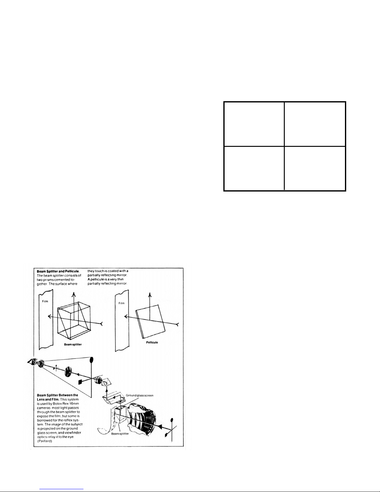
Reex Viewnder
The optical system of the Bolex H16 reex
permits through the lens viewing at all times.
This system utilizes a beam splitter so the
image seen in the viewnder is completely
free from icker. The reex nder enables
accurate focusing and framing, and allows
you to estimate the depth of eld. The reex
prism deects 20-25% of the light passing
through the lens into the viewnding system.
Only 75-80% reaches the lm plane. The
actual quality of light reaching the lm is
reduced by about 1/2 to 1/3 of an f-stop. To
compensate for this, Bolex has determined
that the effective shutter speed for the H16
camera is 1/80 second rather than the
standard 1/65 of a second. To further confuse
matters, Bolex (in conjunction with Kern/
Switar) has designed a series of lenses which
are calibrated to pass 1/2 to 1/3 stop more
light that the aperture markings on the barrel
indicate, compensating for the light lost to the
viewnding system.
The letters “rx” designates these lenses after
the name on the barrel. When using these
lenses with the H16 camera, the effective
exposure is back to 1/65 of a second.
Bolex H16 Other Camera
Read exposure
meter at
1/65 a second
Read exposure
meter at
1/65 a second
Under expose
lm by 1/3
to 1/2 stop
Read exposure
meter at
1/80 a second
RX
Non
RX
Diopter Adjustment
This adjustment corrects the optical system
to the operatorʼs eyesight (whether or not if
s/he wears glasses) and remains the same
for all lenses on the camera.
To set the diopter:
1. Turn the turret to expose the reex
prism (no lens in taking position).
2. View a well-lighted subject.
3. Loosen the grooved ring around the
viewnder and turn the lever until the
grain of the ground glass is perfectly
sharp.
4. Tighten the ring that acts as a lock nut.
Some viewnders have locking screws.
Douser
The douser (located on the reex viewnder)
closes the eyepiece to keep light from
reaching and fogging the lm plane through
the viewnder.
3
Warning: Light meters in Media Loan are calibrated for 180º
angle shutter not the 135º angle shutter in the Bolex H16

Diopter Adjust
Eyecup
Diopter Lock
It is necessary to use the douser when
doing pixilation with a strong light behind the
camera. The douser is open when the lever
is in the horizontal position; closed in the
vertical position.
Turret
By turning the turret you can change from
one lens to another. To turn the turret, use
its fold away lever rather than handling
the lenses. In this way, there is less risk of
accidentally changing the aperture and/or
focus ring. When using heavy lenses, such
as telephotos or zooms, the turret should be
locked with either a special locking clamp
or a turret plug. Turret plugs go into the
lowest lens cavity (when turret is on normal
position); they are marked with a red ring.
For other lighter lenses, the turret lock on
the camera should be sufcient. This lock is
located above the lens in the taking position
and should be tighten before the lenses are
in place. Keep the wide-angle lenses and
telephoto lens opposite of each other on the
turret so the telephoto lens doesnʼt interfere
with the eld of view of the wide-angle lens.
Filters
The H16 camera has a lter between the
taking lens position and the reex prism. The
lters therefore remain in place no matter
which lens is used. When lming without a
lter, an empty lter carrier should be left in
the lter slot to prevent light from entering
the slot and fogging the lm. Make sure the
carrier is located rmly within the slot and
the correct lter is in place before shooting.
An incorrect lter will either alter the color
balance or exposure.
Turret Lock
Filter Slot
Turret
Turret Lock Screw
Release Button
Lens Taking Position
4

Camera Motor
The Bolex H16 has its own internal spring
drive motor. This allows an electric motor to
be used and also allows you to backwind
the lm for camera dissolves. Turn the motor
disengaging lever to “MOT” and move the
slide release to “stop”. If the side release will
not go to stop, slightly wind the spring. Lift the
winding crank, which automatically engages
the spindle, and turn counterclockwise. Wind
the spring fully without forcing it. Fold the
crank and secure it on the latch on the lower
body. Fully wound, the motor will drive about
eighteen feet of lm through the camera
(about 28 seconds at 24fps).
IMPORTANT: Never leave the camera wound
during storage. This may ruin the spring.
When running down the spring with no lm in
the camera, set lm speed at 8fps.
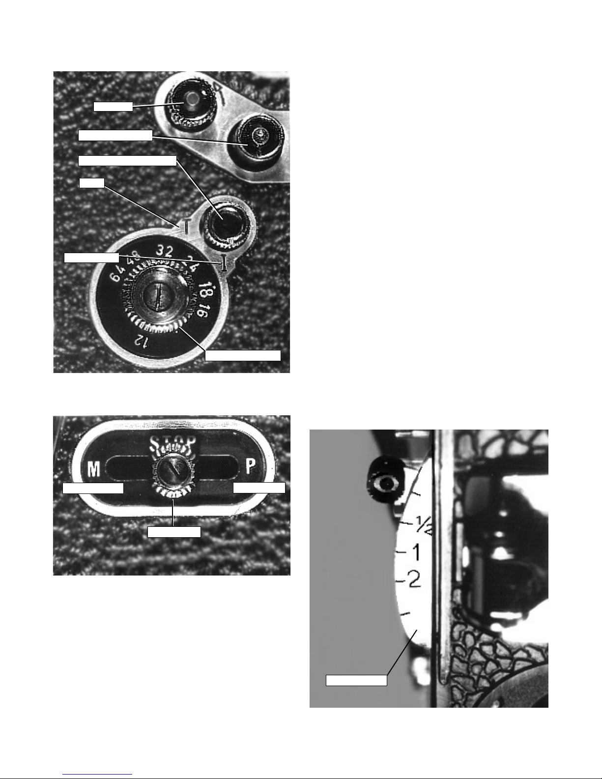
Film Speeds
The camera has seven lm speeds from 12
to 64 frames per second (fps). To select the
desired speed, turn the control knob until the
corresponding gure is opposite the red dot.
When changing lming speeds do not forget
to alter the exposure setting. (When changing
from 24 to 48 by one stop and so forth.)
Release Selector (on/off)
The H16 can be used for normal, continuous,
or single frame lming. The different
operations are controlled by the side release.
Normal lming-- This method is suitable for
most shooting situations. Then camera runs
as long as the operator depresses the front
release or pushes the side release towards
“M.”
Continuous lming-- Push the side release
towards “M” until it clicks into place. The
camera will continue running until the wind
runs out or the side lever is pushed to the
STOP position.
Turret Lock
Filter holer
MOT
Spring Disengage Lever
Disengage
5
Backwind
Electric Motor Shaft
Extended Exposure Select
Instantaneous
Film Speed Selector
Time
Single frame lming-- Instantaneous: Turn
the knob until the guide mark is in the “I”
position. The effective exposure time in this
position is 1/30 of a second. Time: Place
guide mark in “T” position; shutter will remain
open as long as side release is in the “P”
position.
Variable Shutter
The H16 is equipped with a shutter whose
aperture can be varied when the camera is
running and when it is stopped. This enables
you to reduce exposure time without altering
the camera running speed or f-stop. In bright
light, the variable shutter can be used to
reduce exposure, therefore eliminating the
need for a neutral density lter.
The shutter may be locked in each of its four
positions by pulling it out and pushing in
when at the desired setting.
Fully open -- normal exposure -- at the red
mark.
1/4 closed -- exposure reduced by a half stop
1/2 closed -- exposure reduced by a full stop
Fully closed -- no light reaching the lm plane
In some cameras, a triangular warning signal
will appear in the viewnder if the variable
shutter is not in the fully open position.
Variable Shutter
Continuous Run Single Frame
Slide Release
6

Lap Dissolve
Superimposing a fade-in on a fade-out makes
a lap dissolve so that one picture gradually
disappears as the next gradually appears.
This allows for a smooth transition during
which the picture brightness scarcely varies.
To produce lap dissolve, close the rst shot
in a sequence with a fade-out. Lock the
shutter in the “closed” position. Set the frame
control to zero. Disengage the motor. Set
the slide release to the ʻMʼ position. Douse
the Viewnder. Cap the lens. Rewind the
lm, using the backwind key, until the frame
counter indicates the duration of the fade-out.
Move the slide release to the STOP position.
Frame the second sequence to be lmed
and release the slide lever. At the same time
make a fade-in the same length as the fade-
out.
Duration of the
fade
in seconds
Number of frames/
Filming Speed
18 fps 24 fps
973
964
955
973
964
952
940
928
1 1/2
3
2
2 1/2
Loading the Camera
Before loading:
1. Set side release to stop.
2. Set disengaging motor to MOT.
3. Turn FPS selector knob until the number
corresponding to the desired camera speed
faces the red dot.
4. Wind the camera.
Check that the pressure plate pin is locked so
that the pressure plate cannot open.
The lm will jam at this point if the plate is
not closed. Remove the empty spool from
its spindle by pressing the ejector. Place
the loaded daylight spool on the upper
spindle. (Film should come off in the direction
indicated by the engraved arrow).
IMPORTANT: At the lm gate the emulsion
should always face towards the front of the
camera.
Using the lm knife (located at the bottom of
the camera), clip the lm end.Close the loop
formers by moving the control lever parallel
to the pressure plate. Insert lm end in the
top feed sprocket and start the camera motor.
The lm is automatically threaded through
the gate. If you need to adjust the lm, you
can spread the sprocket guides by sliding the
locking plate forward.
Continue to run the camera until 12 to 15
inches of lm have passed through the drive
mechanism.
Open the loop formers by pressing the button
located on the sprocket/gate assembly. Insert
the lm end into the take-up spool (in the
direction of the engraved arrow), place the
spool on the lower spindle and take up any
Loop Formers
Pressure Plate Pin
Sprocket Guides
Release
Sprocket Guide Lock
7
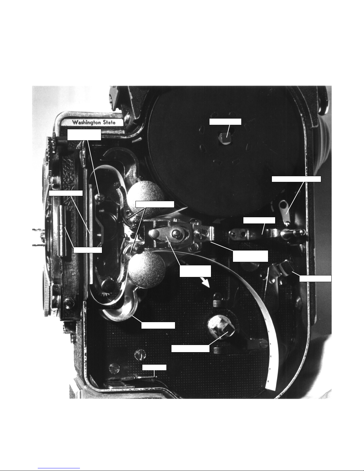
Camera Diagram
Feed Spindle
Sprocket Guides
Audible Signal Select
Spool Ejector
Pressure Plate
Release Pin
Pressure Plate
Filter Holder
Loop Former
Lock Release
Loop Formers
Film Knife
Retaining Arm
Sprocket Guide
Lock Release
Take Up Spindle
8
slack by hand. Run the camera again for
several seconds to make sure that everything
is okay (check that the lm is advancing
normally and the loops do not scrape the
body). Replace the lid and lock.
Footage Counter
The footage counter indicates how much lm
has been exposed. Once the camera has
been loaded, the counter will read FEET.
Run the camera until the gure “0” appears
opposite the white line in the indicator
window. This indicates the lm leader has
been taken up and the camera is ready to be
used.
The counter will automatically return to “0”
when the lid is removed.
When shooting a 24 fps, there is the option
for an audible CLICK every second indicating
that 8 inches of lm has passed through the
camera. This can be useful when timing a
pan or zoom shot. For an audible CLICK,
move the audible signal select lever down
when loading lm; for no click place the lever
in the “0” position.
Troubleshooting
Problem and Probable Cause
Film is black:
Variable lens shutter was closed
Lens cap left on
Exposure incorrect
Film underexposed, images reversed; with
color lm, general orange tint:
Film incorrectly loaded with the base facing
forward instead of the emulsion
Jumpy Images:
Loops formed incorrectly
Shrunken lm stock
Prevailing red-orange tint:
Using tungsten lamps with a daylight lm or
an underpowered tungsten lamp
Obscured Images:
Turret Incorrectly positioned
Telephoto lens on turret obscuring view of
other lenses
Partly obscured pictures:
Telephoto lens in the way of the taking lens or
turret badly positioned
Parallel scratches on the edge of the lm:
Dust or particles of emulsion in the lm gate
Camera poorly loaded
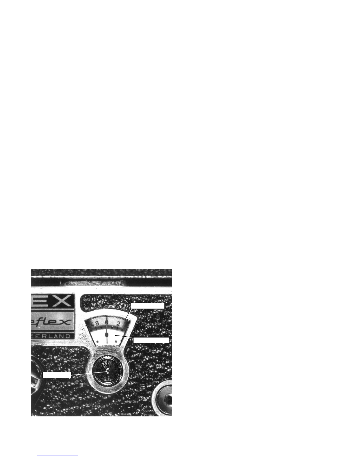
Frame Counter
100ʼs of Frames
Frame Reset
9
Frame Counter
The frame counter is helpful for lap dissolves,
double exposures, and animation.
The upper dial adds the frame in forward
run and subtracts them in reverse (0 to 50
frames).
The lower dial totals in unit of 50 frames.
It will subtract when the camera runs in
reverse.
Indicators are from 0 to 1000 frames.

Fogged lm:
Light entering through the viewnder or lter
slot
Film was loaded in extremely bright light
Camera not seated well
Film fogged at edges:
Camera loaded in strong light
Warped take up or feed reel
Filter carrier not in slot during exposure
Out of focus or “breathing” pictures:
Pressure plate incorrectly locked
Exposure Meter Shoe
Filter Holder
Carrying Handle
Optical Viewnder Bracket
Lid Lock
Exposure Meter Shoe
Turret Lever
Magazine Cavity Cover
Turret Locking Screw
Starting Button
Exposure Meter Shoe
10
Troubleshooting Continued
Referance Illustrations
Table of contents
Other BOLEX Camcorder manuals


-A Technical manual")


