Bosch LTC 3384 User manual

Series DC-iris Zoom Lenses
Installation Manual
EN LTC 3384
Guide de l'utilisateur
FR LTC 3384
Bedienungsanleitung
DE LTC 3384
Manual de instrucciones
ES LTC 3384
Handleiding
NL LTC 3384
Manuale d'istruzioni
IT LTC 3384
LTC3384_IN_93583.qxd 6/26/03 2:35 PM Page 1

Important Sa ety Instructions
Applications
The Bosch 1/3” DC-iris Zoom
Lenses provide high quality optics
or state-o -the-art CCTV cameras.
DC-iris
The DC-iris direct drive eature
automatically adjusts the iris opening
according to lighting conditions. This
ensures optimum picture quality in
applications with changing light
levels, or example, in outdoor
observation.
Zoom and Focus
Zoom and ocus are driven by
motors, allowing sharp images
ranging rom wide angle to
telephoto.
Connection and Mounting
The lenses are itted with two
terminated cables and a CS camera
mount.
Type Number Zoom Mount
LTC 3384/21 10x, 6-60 mm CS
DC-iris Connection: A 200 mm
cable terminated with a 4-pin EIAJ
plug or direct connection to Bosch’
camera heads.
Zoom and Focus Connection: A
400 mm cable terminated with 8-pin
connector or connection to a zoom/
focus controller.
Lens Mounting: To attach the lens to
the camera head:
1. Screw the lens into the camera
head until it completely stops.
2. Rotate the lens back to the
desired position (there is a
riction coupling between the
CS-mounting and the lens body
that allows 360° rotation).
Controls
Zoom and Focus Control: Zoom
and ocus are controlled by speci ic
signals supplied rom the zoom/ ocus
controller via the zoom/ ocus control
cable. The zoom and ocus motors
are activated while the signals are
present and stop when the signals
are removed.
LTC 3384 | Installation Instruction EN | 2
Bosch Security Systems | 06 2003 | ersion 93584
Warning: Do not use the
lens to look at the sun. It
may cause loss o sight.
Attention: Do not direct
the lens into the sun. It
may cause a ire.
Caution: Use 1/3” format CS-
mount lenses only with 1/3”
format cameras with CS-mount.
LTC3384_IN_93583.qxd 6/26/03 2:35 PM Page 2

Zooming and Focusing procedure:
1. Apply zoom control signals to
set the zoom to “TELE” end.
2. Apply focus control signals and
align focus.
3. Apply the zoom control signals
to set the required angle of field.
4. If the image becomes out of
focus due to zooming, adjust the
back focus (see below).
Back Focus Adjustment:
4-wire control
3-wire control
(which can be focused on
easily).
2. Set the zoom to “WIDE” and
align the focus with the camera
(refer to the camera
instructions).
3. Set the zoom to “TELE” and
align the focus with the lens.
4. Repeat the above procedures
several times until the focus at
both ends of the zoom range
(WIDE and TELE) are most
appropriate.
Cable Connection
Focus/Zoom (8-Pin Female Connector)
Pin Polarity Direction
Focus 6 + Inf.
5 -
6 - Near
5 +
Pin Polarity Direction
Zoom 6 + Wide
4 -
6 - Tele
4 +
|4833CTL3|NE Installation Instruction
Bosch Security Systems | 06 2003 | Version 93584
LTC3384_IN_93583.qxd 6/26/03 2:35 PM Page 3
Pin Polarity Direction
Focus 2&6 + Inf.
5 -
2&6 - Near
5 +
Pin Polarity Direction
Zoom 2&6 + Wide
2&6: Connect pins 2 and 6 together
4 -
2&6 - Tele
4 +

Specifications
Focus/Zoom
Input Voltage: 6 - 12 VDC
Current Consumption: 70 mA max.
Motorization Speed: Approx. 3-4 s
DC-iris
Response speed: Approx. 2 s
Temperature
Range: -5 to +50 °C
(23 - 122 °F)
LTC 3384 | Installation Instruction EN | 4
Bosch Security Systems | 06 2003 | Version 93584
LTC3384_IN_93583.qxd 6/26/03 2:35 PM Page 4
DC-iris (4-Pin DC-Iris Lens Connector)
Pin Polarity Connection
3 + Driving Coil
4 -
1 - Damping Coil
2 +
DC-Iris Connector 8-PIN Female Connector
(both viewed from solder side)
1
2
3
4
6
8
3
5
2
4
1
7

Sécurité
Applications
Les objecti s 1/3" iris-DC zoom à
diaphragme automatique Bosch sont
constitués d'éléments optiques de
haute qualité. Ils sont destinés aux
caméras de TV en circuit ermé les
plus per ormantes.
Diaphragme automatique
Le diaphragme automatique adapte
automatiquement l'ouverture de l'iris
aux conditions d'éclairement. II
garantit une qualité optimale de
l'image dans des applications sujettes
à des variations de niveaux de
lumière, par exemple dans les
applications en extérieur.
Zoom et mise au point
Le réglage de zoom et de mise au
point sont contrôlés par des moteurs,
ce qui permet d'obtenir des images
très nettes soit en objecti grand-
angle soit en téleobjecti .
Raccordements et ixation
Ces objecti s zoom sont munis de
deux câbles avec iche et d'une
monture CS.
Numéro de typer Zoom Fixation
LTC 3384/21 10x, 6-60 mm CS
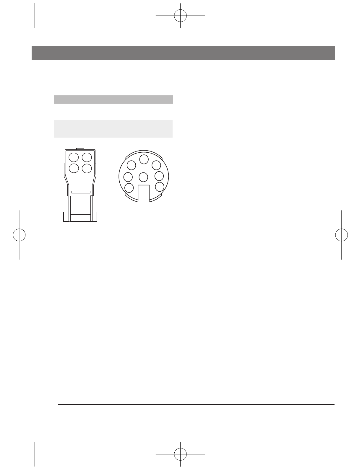
Raccordement du diaphragme
automatique: Les objecti s sont
dotés d'un câble de 20 cm de long
terminé par une prise à 4 broches
pour le raccordement direct sur les
caméras Bosch.
Connecteur pour zoom et mise au
point: Ils sont également équipés
d'un câble de 40 cm de long terminé
par un connecteur 8 broches pour le
raccordement direct sur un récepteur
de télécommande de zoom/mise au
point.
Montage de 'objecti : Pour ixer
l'objecti sur la caméra:
1. Visser à ond l'objecti sur la
caméra jusqu' à in.
FR | 5 LTC 3384 | Guide de l'utilisateur
Bosch Security Systems | 06 2003 | ersion 93584
Attention: N'utilisez pas
l'objecti pour regarder le
soleil. Ceci pourrait
occasionner une cécité.
Attention: Ne dirigez pas
l'objecti vers le soleil.
Ceci pourrait occasionner
un incendie.
Attention: Avec les caméras à
capteur 1/3" et monture CS, il
est recommandé d'utiliser
uniquement des objectifs à
monture CS de format 1/3" ou
1/2"
LTC3384_IN_93583.qxd 6/26/03 2:35 PM Page 5

2. Faire pivoter l'arrière de
l'objecti jusqu' à la position
désirée (il existe un couple de
riction entre la monture CS et
le corps de l'objecti , permettant
une rotation sur 360°).
Commandes
Commandes de zoom et de mise
au point: Le zoom et la mise au
point sont commandés par des
signaux émis à partir du contrôleur
de télécommande de zoom/mise au
point, par l'intermédiaire du câble de
commande zoom/mise au point. Les
moteurs du zoom et de mise au point
se déclenchent dès réception des
signaux. Ils s'arrêtent guard les
signaux sont supprimés.
Procédure d'exploitation du zoom
et de Ia mise au point:
1. Appliquer les signaux de
commande du zoom de manière
à régler le zoom du côté
"TELE".
2. Appliquer les signaux de la
commande de mise au point
pour régler celle-ci.
3. Appliquer les signaux de
commande de zoom a in de
régler l'objecti pour obtenir
l'angle de champ requis.
4. Si, en réglant le zoom, l'image
perd sa netteté, régler le tirage
optique (voir ci-dessous).
Réglage du tirage optique:
1. Sélectionner un objet
relativement grand (sur lequel il
sera acile de aire la mise au
point) et éloigné de 15 mètres
minimum.
2. Régler le zoom sur "WIDE"
(Grand angle) et aligner la mise
au point avec la monture de la
caméra (se reporter à la notice
de la caméra, réglage du tirage
optique).
3. Régler le zoom sur "TELE" et
régler la mise au point sur la
bague de l'objecti .
4. Recommencer à plusieurs
reprises les procédures ci-dessus
jusqu'à ce que la mise au point
soit constante sur toute la
gamme de réglage du zoom
(GRAND-ANGLE et
TELEOBJECTIF).
LTC 3384 | Guide de l'utilisateur FR | 6
Bosch Security Systems | 06 2003 | ersion 93584
LTC3384_IN_93583.qxd 6/26/03 2:35 PM Page 6

Branchement du câble
Mise au point/Zoom (Connecteur 8-
Broche)
Broche Polarité Direction
Mise au 2 + Inf.
point 5 -
2 - Près.
5 +
Broche Polarité Direction
Zoom 6 + Grand angle
4 -
6 - Téléobjectif
4 +
Iris DC (Connecteur 4-Broche)
Broche Polarité Connexion
3 + Bobine d'entraînement
4 -
1 - Bobine d'amortissement
2 +
Connecteur iris DC Connecteur 8-Broche
(Vue depuis le côté des soudures)
Spécifications
Mise au point/Zoom
Tension en
Commande 4 fils
Commande 3 fils
entrée : 6 - 12 V cc
Consommation
réelle : 70 mA max.
Vitesse de
motorisation : Approx. 3-4 sec.
Iris DC
Vitesse de
réaction : Approx. 2 sec.
Température
Plage : -5 à +50°C
|4833CTL7|RF Guide de l'utilisateur
Bosch Security Systems | 06 2003 | Version 93584
1
2
3
4
6
8
3
5
2
4
1
7
LTC3384_IN_93583.qxd 6/26/03 2:35 PM Page 7
Broche Polarité Direction
Mise au 2&6 + Inf.
point 5 -
2&6 - Près.
5 +
Broche Polarité Direction
Zoom 2&6 + Grand angle
4 -
2&6 - Téléobjectif
4 +
2&6: reliez les broches 2 et 6

Sicherheit
Anwendung
Die Bosch 1/3” Zoom-Objektive mit
gleichstromgesteuerter Blende
optischen Qualität sind ür den
Einsatz an modernen
Überwachungskameras bestimmt.
Blendenautomatik
Die Blendenautomatik paßt die
Blendenö nung den gegebenen
Lichtverhältnissen an. Die Automatik
sorgt ür eine optimale Bildqualität
auch bei stark schwankenden
Beleuchtungsverhältnissen, z. B. Im
Freien.
Zoom und Fokus
Die Einstellungen ür Zoom und
Fokus er olgen mit Hil e von
Motoren. Dies gewährleistet eine
hohe Bildschär e vom Weitwinkel-
bis Tele-Bereich.
Anschlüsse und Installation
Die Objektive werden an der
Kamera mechanisch über den CS-
Mount und elektrisch über zwei
Kabel mit Steckverbindern
angeschlossen.
Typennummer Zoom Objektiv-Fassung
LTC 3384/21 10x, 6-60 mm CS
Anschluß der Blendenautomatik:
An den Objektiven be indet sich ein
200 mm langes Kabel mit einem 4-
poligen EIAJ-Stecker zum direkten
Anschluß an Bosch
Uberwachungskameras.
Anschluß ur Zoom und Fokus: Ein
weiteres 400 mm langes Kabel mit
8 poligem Stecker ür Zoom
und Fokus angeschlossen.
Einsetzen des Objektivs: Das
Objektiv wird wie olgt an der
Kamera be estigt:
1. Schrauben Sie das Objektiv bis
zum Anschlag in die Kamera.
2. Drehen Sie das Objektiv in die
gewünschte Position (zwischen
dem CS-Mount und dem
Objektivgehäuse be inder sich
eine Rutschkupplung, die eine
Drehung um 360° erlaubt).
LTC 3384 | Bedienungsanleitung DE | 8
Bosch Security Systems | 06 2003 | ersion 93584
Warnung: Mit diesem
Objektiv nicht in die
Sonne blicken. Erblindung
kann die Folge sein.
Achtung: Das Objektiv
nicht in die Sonne richten.
Brandge ahr
Achtung: CS-Mount Objektive
für das 1/3” Format dürfen nur
an 1/3” Kameras mit CS-Mount
eingesetzt werden.
LTC3384_IN_93583.qxd 6/26/03 2:35 PM Page 8

Steuerung
Steuerung von Zoom und Fokus:
Zoom und Fokus werden durch
eigene Steuersignale vom
Zoom/Fokus-Steuergerät über das
entsprechende Kabel eingestellt. Die
Einstellmotoren für Zoom und Fokus
drehen, solange das Signal anliegt,
und halten an, sobald das
entsprechende Steuersignal wieder
abgeschaltet wird.
Einstellen des Zooms und der
Fokussierung:
1. Bringen Sie das Zoom mit Hilfe
des entsprechenden Steuergeräts
an die Tele-Endposition.
2 Stellen Sie mit Hilfe des Fokus-
Steuersignals die Bildschärfe ein.
3 Stellen Sie nun mit dem Zoom-
Steuersignal den gewünschten
Bildwinkel ein.
4 Wenn sich beim Verstellen des
Zooms die Bildschärfe ändert,
muß das Auflagemaß justiert
werden (siehe unten).
Einstellung des Auflagemaßes:
1. Richten Sie die Kamera auf
einen größeren Gegenstand (der
sich leicht scharfstellen (läßt).
2 Bringen Sie das Zoommobjektiv
in Stellung Weitwinkel und
3-Draht steuerung
4-Draht steuerung
2&6: Pin 2 und 6 gemeinsam verbinden
stellen Sie die Schärfe über das
Auflagemaß der Kamera em
(siehe Bedienungsanleitung der
Kamera).
3 Stellen Sie das Zoom auf Tele
und stellen Sie am Objektiv
scharf.
4 Wiederholen Sie diesen Vorgang
solange, bis sich bei den beiden
Fokuseinstellungen (Weitwinkel
und Tele) keine Verbesserung
mehr ergibt.
Kabelanschluß
Fokus/Zoom (Anschluß 8-Stift)
Stift Polarität Richtung
Fokus 2 + Unendlich
5 -
2 - Nah
5 +
Stift Polarität Richtung
Zoom 6 + Weitwinkel
4 -
6 - Tele
4 +
|4833CTL9|ED Bedienungsanleitung
Bosch Security Systems | 06 2003 | Version 93584
LTC3384_IN_93583.qxd 6/26/03 2:35 PM Page 9
Stift Polarität Richtung
Fokus 2&6 + Unendlich
5 -
2&6 - Nah
5 +
Stift Polarität Richtung
Zoom 2&6 + Weitwinkel
4 -
2&6 - Tele
4 +

Anschluß für Anschluß 8-Stift
gleichstromgesteuerte
Blendenregelung
(Von der Löseite aus bettrachtet)
Technische Daten
Fokus/Zoom
Eingangsspannung: 6 - 12 VDC
Stromverbrauch: max. 70 mA
Motorgeschwindigkeit: ca. 3 - 4 Sek.
Gleichstromgesteuerte
Blendenregelung
Reaktionsgeschwin-
digkeit: ca. 2 Sek.
Temperatur
Temperatur-bereich: -5 bis +50°C
LTC 3384 | Bedienungsanleitung DE | 10
Bosch Security Systems | 06 2003 | Version 93584
1
2
3
4
6
8
3
5
2
4
1
7
LTC3384_IN_93583.qxd 6/26/03 2:35 PM Page 10
Gleichstromgesteuerte Blende
(Anschluß 4-Stift)
Pin Polarität Anschluß
3 + Antriebsspule
4 -
1 - Dämpferspule
2 +

Seguridad
Aplicaciones
Las lentes con 1/3” DC-iris zoom y
con iris automático proporcionan
una óptica superior para cámaras
CCTV de tecnología de vanguardia.
Iris automático
El dispositivo de iris automático
ajusta automáticamente la apertura
del iris de acuerdo con las
condiciones de luminosidad. Esto
asegura una calidad deimagen
óptima en condiciones de
luminosidad variable como por
ejemplo en observaciones exteriores.
Lente con zoom y en oque
Las lentes con zoom y en oque se
ajustan mediante motores eléctricos,
lo que asegura una imagen clara a
cualquier distancia ocal, desde
panorámica hasta primer plano.
Conexiones y montaje
Las lentes poseen dos cables con
terminales y montura de cámara CS.
Modelo Zoom Montaje
LTC 3384/21 10x, 6-60 mm CS
Conexiones del iris automático: La
lente posee un cable de 200mm con
un conector 4polar para su conexión
directa a la cabeza de la cámara
Bosch.
Conector de la lente zoom y
en oque: Poseen también un cable
de 400 milímetros con un connector
de 8 patillas para su conexión al
controlador de la lente zoom y el
en oque.
Montura de Ia lente: Para colocar la
lente en la cabeza de las cámaras:
1. Enrosque la lente en la cabeza
de la cámara hasta que haga
tope.
2. Gire la lente hacia atrás hasta
que obtenga la posición deseada
(existe un acoplador de ricción
entre la montura CS y el cuerpo
de la lente que permite una
rotación de 360°).
ES | 11 LTC 3384 | Manual de instrucciones
Bosch Security Systems | 06 2003 | ersion 93584
Advertencia: No use la
objetivo para mirar al sol.
Puede causar la pérdida
de la vista.
Atención: No deje que el
sol se re leje en la
objetivo. Puede causar un
incendio.
Aviso: Use ena lente de
montura CS de formato de 1/3”
de pulgada solamente con
cámaras con formato de 1/3”
de pulgada con montura CS.
LTC3384_IN_93583.qxd 6/26/03 2:35 PM Page 11

Controles
Control de zoom y enfoque: El
zoom y el enfoque son controlados
por señales especificas suministradas
por el controlador de la lente a
través del cable. Los motores del
zoom y el enfoque son activados
mediante una señal y se desactivan
tan pronto como desaparece dicha
señal.
Procedimiento de enfoque:
1. Aplique la señal de control de
zoom para ajustar el zoom al
final de "TELE".
2. Aplique señales de control de
enfoque y corrija el enfoque.
3. Aplique señales de control de
zoom para obtener el ángulo de
vista requerido.
4. Si la imagen se desenfoca
debido a cambios de distancia
focal, ajuste la distancia focal de
la última lente (véanse los
apartados siguientes).
Ajuste de Ia distancia focal de Ia
última lente:
1. Seleccione un objeto bastante
grande (que se pueda enfocar
control de 4 hilos
control de 3 hilos
2&6: conecta las patillas 2 y 6
fácilmente).
2. Ponga el zoom a "WIDE" (gran
angular) y corrija el enfoque con
la cámara (consulte las
instrucciones de la cámara).
3. Ponga el zoom a "TELE" y
corrija el enfoque con la lente.
4. Repita el procedimiento anterior
varias veces hasta que el
enfoque en ambos extremos de
las distancias del zoom (WIDE
Y TELE) estén correctas.
Conexión de los cables
Foco/Zoom (Conector 8-Patilla)
Patilla Polaridad Dirección
Focus 2 + Inf.
5 -
2 - Próxima
5 +
Patilla Polaridad Dirección
Zoom 6 + Amplia
4 -
6 - Tele
4 +
LTC 3384 | Manual de instrucciones ES | 12
Bosch Security Systems | 06 2003 | Version 93584
LTC3384_IN_93583.qxd 6/26/03 2:35 PM Page 12
Patilla Polaridad Dirección
Focus 2&6 + Inf.
5 -
2&6 - Próxima
5 +
Patilla Polaridad Dirección
Zoom 2&6 + Amplia
4 -
2&6 - Tele
4 +

Conector de autoiris Conector 8-Patilla
(Vista desde el lado del soldador)
Especificaciones
Foco/Zoom
Tensión de entrada: 6 - 12 Vc.c.
Consumo de
corriente: 70 mA máx.
Velocidad de 3-4 seg. aprox.
motorización:
Autoiris
Velocidad de
respuesta: 2 seg. aprox.
Temperatura
Rango: -5 a +50°C
|4833CTL31|SE Manual de instrucciones
Bosch Security Systems | 06 2003 | Version 93584
1
2
3
4
6
8
3
5
2
4
1
7
LTC3384_IN_93583.qxd 6/26/03 2:35 PM Page 13
Autoiris (Conector 4-Patilla)
Patilla Polaridad Conexión
3 + Bobina de
4 - dirección
1 - Bobina de
2 + compensación

Veiligheid
Toepassingen
Bosch 1/3” DC-dia ragma
zoomlenzen zijn optische lenzen van
hoge kwaliteit welke geschikt zijn
voor geavanceerde CCTV camera's.
Auto-dia ragma
Het DC-dia ragma stelt, naar gelang
de lichtcondities, het dia ragma
automatisch in. Hierdoor wordt
optimale beeldkwaliteit verkregen in
situaties waar verschillende
lichtniveau's aanwezig zijn,
bijvoorbeeld buiten.
Zoom en ocus
Zoom en ocus worden aangedreven
door motoren, waarbij scherpe
beelden van groothoek tot tele oto
worden verkregen.
Aansluitingen en montage
De lenzen zijn uitgerust met twee
kabels met connectors en een CS-
cameravatting
Type Zoom Lensvatting
LTC 3384/21 10x, 6-60 mm CS
DC-dia ragma-aansluiting: De
lenzen hebben een 200mm lange
kabel met een 4-polige EIAJ plug
voor een directe aansluiting op
Bosch cameras.
Zoom en ocus aansluiting: Zij
hebben tevens een 400mm lange
kabel met 8-polige connector voor
aansluiting op een zoom/ ocus
besturing.
Montage van lens: Voor het
monteren van de lens aan de
cameras:
1. Schroe de lens net zover in de
lens vatting tot hij stopt.
2. Draai de lens terug naar de
gewenste positie (er is een
rictiekoppeling tussen de CS-
vatting en het lensvatting
waarbij om een hoek van 360°
gedraaid kan worden).
LTC 3384 | Handleiding NL | 14
Bosch Security Systems | 06 2003 | ersion 93584
Waarschuwing: De lens
niet gebruiken om naar de
zon te kijken. Dit kan
leiden tot verlies van het
gezichtsvermogen.
Let op: De lens niet op de
zon richten. Dit kan brand
veroorzaken.
Waarschuwing: Gebruik 1/3”
lenzen met CS-vattingen alleen
met 1/3” camera’s met CS-
vattingen.
LTC3384_IN_93583.qxd 6/26/03 2:35 PM Page 14

Besturingen
Besturing van zoom en focus:
Zoom en focus worden door
specifieke signalen bestuurd welke
door de zoom/focus besturing via de
zoom/focus besturingskabel worden
geleverd. Wanneer de signalen
aanwezig zijn worden de zoom en
focus motoren aangezet en wanneer
de signalen verdwijnen stoppen ze.
Procedure voor zoomen en
scherpstellen:
1. Stel, met gebruik van
zoombesturingssignalen, de
zoom op 'TELE' in.
2. Stel, met gebruik van
focusbesturingssignalen, het
4-draads besturing
3-draads besturing
2&6: verbindt pen 2 met 6
beeld scherp.
3. Stel, met gebruik van
zoombesturingssignalen, de
gewenste hoek in.
4. Wanneer het beeld onscherp
wordt als gevolg van zoomen
stel de achterfocus dan af (zie
beneden).
Afstellen van achterfocus:
1. Kies een relatief groot voorwerp
liets wat gemakkelijk
scherpgesteld kan worden.
2. Stel zoom op 'WIDE'
(groothoek) in en stel het beeld
met de camera scherp (zie de
instructies voor de camera).
3. Stel zoom op 'TELE' in en stel
het beeld met de lens scherp.
4. Herhaal de bovenstaande
procedures verscheidene malen
tot de scherpstelling aan beide
einden van het zoombereik
(WIDE en TELE) juist zijn.
Cable Connection
Focus/Zoom (Connector 8-Pen)
Pen Polariteit Richting
Focus 2 + Oneindig
5 -
2 - Dichtbij
5 +
Pen Polariteit Richting
Zoom 6 + Groothoek
4 -
6 - Tele
4 +
|4833CTL51|LN Handleiding
Bosch Security Systems | 06 2003 | Version 93584
LTC3384_IN_93583.qxd 6/26/03 2:35 PM Page 15
Pen Polariteit Richting
Focus 2&6 + Oneindig
5 -
2&6 - Dichtbij
5 +
Pen Polariteit Richting
Zoom 2&6 + Groothoek
4 -
2&6 - Tele
4 +

DC-diafragmaconnector 8-Pen connector
(Gezien vanaf de solderzijde)
Technische gegevens
Focus/Zoom
Ingangsspanning: 6 - 12 V DC
Stroomverbruik: max. 70 mA
Motorsnelheid: ong. 3 tot 4 sec.
DC-diafragma
Reactiesnelheid: ong. 2 sec.
Temperatuur
Bereik: -5°C tot +50°C
LTC 3384 | Handleiding NL | 16
Bosch Security Systems | 06 2003 | Version 93584
1
2
3
4
6
8
3
5
2
4
1
7
LTC3384_IN_93583.qxd 6/26/03 2:35 PM Page 16
DC-diafragma (Connector 4-Pen)
Pen Polariteit Functie
3 + Aanstuurspoel
4 -
1 - Dempspoel
2 +

Sisurezza
Applicazioni
Gli 1/3” obbiettivi DC-iris zoom
Bosch con dia ramma ad iride
automatico o rono un'ottica di
elevatissima qualità per le più
moderne telecamere a circuito
chiuso.
Dia ramma ad iride automatico
La caratteristica del dia ramma ad
iride signi ica che la regolazione di
apertura dell’iride avviene
automaticamente secondo le
condizioni di luce, garantendo in tal
modo la qualità dell’immagine in
applicazioni soggette a variazioni dei
livelli di luce, ad esempio in
osservazioni all’aperto.
Zoom e messa a uoco
Lo zoom e la messa a uoco sono
condotti da motori, consentendo di
ottenere immagini nette sia in
panoramica che in tele oto.
Collegamento e montaggio
I obbiettivi sono muniti di due cavi a
ine e di montatura CS per
telecamera
Modello Zoom Montaggio
LTC 3384/21 10x, 6-60 mm CS
Collegamento del dia ramma ad
iride automatico: Gli obbiettivi sono
muniti di un cavo di 200mm di
lunghezza, che termina con una
spina a 4 poli per collegamento
diretto alla testina della telecamera
Bosch.
Collegamento del zoom e della
messa a uoco: Gli obbiettivi sono
anche muniti di un cavo di 400mm
di lunghezza, che termina con un
connetore a 8-piedini per
collegamento ad un controllore dello
zoom/messa a uoco.
Montaggio delI'obbiettivo: Per
sistemare l'obbiettivo sulla testina
della telecamera:
1. Avvitare sino a ermo
l’obbiettivo sulla testina della
telecamera.
2. Ruotare l’obbiettivo all’indietro
sino a raggiungere la posizione
richiesta (un giunto a rizione
sistemato tra la montatura CS e
l'obbiettivo permette la
rotazione di 360°).
IT | 17 LTC 3384 | Manuale d'istruzioni
Bosch Security Systems | 06 2003 | ersion 93584
Pericolo: Non usare
l’objettivo per guardare il
sole. Può causare cecità.
Attenzione: Non puntare
l’objettivo sul sole.
Pericolo d’incendio.
Avvertenza: Usare obbiettivi
con montatura CS con formato
1/3” solo con telecamere con
montatura CS con formato 1/3”.
LTC3384_IN_93583.qxd 6/26/03 2:35 PM Page 17

Comandi
Comando Zoom e Messa a Fuoco:
Il comando dello Zoom e della
Messa a Fuoco viene effettuato da
segnali forniti dal controllore
zoom/messa fuoco mediante il cavo
di comando zoom/messa a fuoco. In
presenza di segnale, i motori dello
zoom e della messa a fuoco vengono
attivati, e disattivati quando il segnale
viene tolto.
Procedura di zoom e di messa a
fuoco:
1. Dare i segnali di comando dello
zoom per impostarlo sulla
funzione 'TELE' (A Distanza).
2. Dare i segnali di comando della
messa a fuoco e tarare la messa
a fuoco.
3. Dare i segnali di comando dello
zoom per impostare l'angolo di
campo desiderato.
4. Se l’immagine dovesse risultare
sfuocata a causa dello zoom,
regolare la retro messa a fuoco
controllo a 4 conduttori
controllo a 3 conduttori
2&6: collegare i piedini 2 e 6 tra loro
(vedi a seguito).
Regolazione Retro Messa a Fuoco:
1. Puntare su un oggetto di grandi
dimensioni (che può essere
facilmente messo a fuoco).
2. Impostare lo zoom a 'WIDE'
(Panoramico) ed allineare la
messa a fuoco con la telecamera
(fare riferimento alle istruzioni
della telecamera).
3. Impostare lo zoom a 'TELE' (A
Distanza) ed allineare la messa a
fuoco con lobbiettivo.
4. Ripetere diverse volte la
procedura suddetta sino ad
ottenere una messa a fuoco
soddisfacente alle due estremità
del campo di zoom (WIDE e
TELE).
Connessione del cavo
Fuoco/Zoom (Connettore 8-Pin)
Pin Polarità Direzione
Fuoco 2 + Inf.
5 -
2 - Vicino
5 +
Pin Polarità Direzione
Zoom 6 + Grandang.
4 -
6 - Tele
4 +
LTC 3384 | Manuale d'istruzioni IT | 18
Bosch Security Systems | 06 2003 | Version 93584
LTC3384_IN_93583.qxd 6/26/03 2:35 PM Page 18
Pin Polarità Direzione
Fuoco 2&6 + Inf.
5 -
2&6 - Vicino
5 +
Pin Polarità Direzione
Zoom 2&6 + Grandang.
4 -
2&6 - Tele
4 +

Connettore DC-iris Connettore 8-Pin
(Vista del lato saldatura)
Specifiche
Fuoco/Zoom
Tensione ingresso: 6 - 12 VCC
Consumo: 70 mA max.
Velocità motore: Circa 3-4 sec.
DC-iris
Velocità risposta: Circa 2 sec.
Temperatura
Gamma: da -5 a +50°C
|4833CTL91|TI Manuale d'istruzioni
Bosch Security Systems | 06 2003 | Version 93584
1
2
3
4
6
8
3
5
2
4
1
7
LTC3384_IN_93583.qxd 6/26/03 2:35 PM Page 19
DC-iris (Connettore 4-Pin)
Pin Polarità Connessione
3 + Avvolg.
4 - pilotaggio
1 - Avvolg.
2 + smorzamento

Bosch Security Systems.
5600 JB Eindhoven
The Netherlands
Tel: +31 (40) 27 80000
Fax: +31 (40) 27 80001
www.boschsecuritysystems.com
3922 988 93584 03-27
Printed in The Netherlands
Updated April 23, 2007
Data subject to change without notice.
LTC3384_IN_93583.qxd 6/26/03 2:35 PM Page 20
Table of contents
Languages:
Other Bosch Camera Lens manuals
Popular Camera Lens manuals by other brands

Fantasea
Fantasea BigEye FP7000 instruction manual

Tamron
Tamron B070 owner's manual

Sony
Sony Alpha FE 28-70mm F3.S-S.6 OSS operating instructions

Olympus
Olympus M.ZUIKO DIGITAL ED 100-400mm f5.0-6.3 IS instructions

Tokina
Tokina Motorized Zoom Lens TM10Z0818GAIDC specification

Sony
Sony SAL-24F20Z Before using

Nikon
Nikon AF Nikkor 24mm f/2.8D instruction manual

Nikon
Nikon AF-S Nikkor 600mm f/4D IF-ED II instruction manual

Pentax
Pentax smc Pentax-FA operating manual

Cyclopital3D
Cyclopital3D Sony PMW-TD300 User instructions

Nikon
Nikon ED 17-55mm f/2.8G IF Repair manual

Nikon
Nikon AF-S DX NIKKOR 16-85mm f/3.5-5.6G ED VR Repair manual